Over and Under or around the sides

Post here information about your own engineering projects, including but not limited to building your own car or designing a virtual car through CAD.
User avatar
Ciro Pabón
106
Joined: 11 May 2005, 00:31

Re: Over and Under or around the sides

Post

Well, if you have time and a winter ahead (summer is almost over) then, would you give a try to the box-fish idea?

I read a couple of years ago about a concept car shaped like the box-fish. Somewhere in this forum I interred my ideas about it (oh, pearls for pigs... what a waste! :D).

Boxfish:

Image

Yeah, it couldn't be less aerodynamic, don't you agree?

However, the theory gives you a Cd of 0.06 for this "horrible" shape.

It has an advantage over other designs: it's boxy! Volvo could reconsider their new image, btw.

This means that you don't have to suffer to accommodate the parts and gadgets under a very hard to mould shape. What could be better than a box for "packaging" and for "moulding"? Well, yes, I know, I'm not that retarded, a sphere would be better, but this isn't about perfectly ideal packaging, it's about easy shaping and about a "roomy" interior, if I have understood GPDR predicament.

So, I started to Google for "boxfish shape aerodynamic efficiency moulding solar power" (if you haven't noticed, I love to give Google huge phrases to try to choke the search engine) and I got this one:

How to design a solar powered car that works

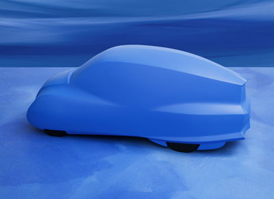
This article has a couple of good images. Of course, one of a boxfish (I already posted one) but also a long disertation about how Mercedes has already tried the idea (probably that was what I read two years ago, some article by Mercedes). They developed this car:

Mercedes Benz Bionic (Cd=0.19)

Image

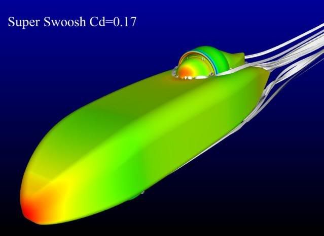
They also give us this "artichoked" shape, with a theoretical Cd of 0.06:

Image

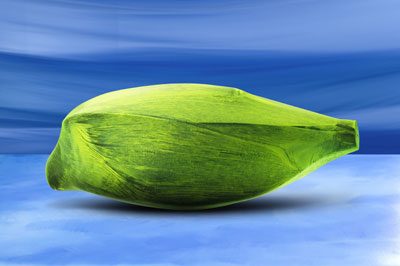
I'm not sure about where resides the differentiation between this shape and a box. Perhaps the "beak" in front? Maybe it's the "raised" (and very "fishy") tail? Frankly, I have no idea, but I guess that flyn "way" to mould could be used with this thing.

I also find interesting this phrase, from a summary about the animal:

"... the skin of the boxfish consists of numerous hexagonal bony plates, interlocked, which provide maximum strength with minimum weight..."

Perhaps the idea to create the body of interlocking parts, unglued, isn't as farfetched as I thought it was. Besides, I think I cannot confound GPDR any more... my work is done. ;)
Ciro

User avatar
flynfrog
Moderator
Joined: 23 Mar 2006, 22:31

Re: Over and Under or around the sides

Post

wow I read that same article a few years ago.

A box fish follows the basics of areo for dummies. Round leading edge no quick transitions and a sharp trailing edge. its pretty close to the tear drop shape but roomier.


another thought make sure to do your coast down both directions and average them out. eliminates the effects of an incline

tok-tokkie
tok-tokkie
38
Joined: 08 Jun 2009, 16:21
Location: Cape Town

Re: Over and Under or around the sides

Post

Image

Besides the quest for the optimal shape you also discussed the paint scheme. This seems to be the optimum for both.

User avatar
Fil
0
Joined: 15 Jan 2007, 14:54
Location: Melbourne, Aus.

Re: Over and Under or around the sides

Post

Boeing 747 has a 0.11 Cd with their shape.. just to add more fuel to the thoughts here.
Any post(s) made by this user are (semi-)educated opinion(s), based on random fact(s) blurred by the smudges of time.
Any fact(s) claimed by this user will be supplemented by a link to the original source of said fact(s).

User avatar
flynfrog
Moderator
Joined: 23 Mar 2006, 22:31

Re: Over and Under or around the sides

Post

Fil wrote:Boeing 747 has a 0.11 Cd with their shape.. just to add more fuel to the thoughts here.
it also has to fly

User avatar
greenpower dude reloaded
6
Joined: 29 Dec 2005, 20:03
Location: Portsmouth, UK

Re: Over and Under or around the sides

Post

RIGHT! I've been away, and subsequently all over the place, anyway!

It seems as though, whilst i've been away that much has been discussed, and I'm incredibly impressed with the subjects that have been brought up.

Interestingly though.. It would seem that the body is not actually too disimilar to that of a box fish albeit elongated, with a drivers head out the top and no mouth...
Image

The edges along the tops at the side are likely to need to be smaller radii than they are in this picture.

This could all be irrelevant in a weeks time, I could potentially have another much bigger project in the pipeline....

Ah actually who am I kidding, I devoted a huge proportion of my life in to rebuilding the chassis over the past two months and have made a start on the body...
______________________________________

BreezyRacer
BreezyRacer
2
Joined: 04 Nov 2006, 00:31

Re: Over and Under or around the sides

Post

Very clean design, but of course, real life around the helmet and roll hoop will be a bit different due to real openings, etc. You might consider adding a large VG in front of the helmet area to reduce drag on the helmet. In addition, you might also consider VGs on the sides, roll hoop, and top surface as the surface begins to taper back.

A vortex generator will set the boundary air to spinning which allows the boundary layer to follow shape changes, thus reducing turbulence and thus drag. You can easily get stick on VGs or make them yourself for testing. Search for vortex generators and you'll find some production car examples even.

As for the VG in front of the helmet, maybe consider a neutral profile wing section maybe 30 mm high, 20 mm wide or so, and maybe 40 mm deep. Mount the front of it maybe 250-300 mm ahead of the helmet. That should give you a nice vortex coming off the tip of the wing and landing directly on the visor of the helmet. A VG reduces drag because it reduces air density as the vortex spins. You have a lot of drag on the face of the helmet.

Do you have any driver entry/exit requirements (usually due to safety you might have to exit the vehicle in 10 seconds, etc). If not you might take a low tack tape to seal up the helmet opening once the driver is in! Do the same around the flange of the helmet to the roll hoop area. Do a nice smooth job with it. Maybe a bit of a "far out there" idea but just imagine how you can freak out your competitors with that! You could even take a 10-15 mil poly and shape it with a heat gun and afix it to the helmet. Just leave the visor area untouched so they cannot say you created a canopy!

One last thing .. as a practical point I would open up the rear bodywork a bit so you cannot get a positive pressure buildup under the bodywork.

User avatar
qw56q
0
Joined: 13 Mar 2009, 21:39

Re: Over and Under or around the sides

Post

Fil wrote:Boeing 747 has a 0.11 Cd with their shape.. just to add more fuel to the thoughts here.
most of which come from the wings which makes the comparison a bit useless.

however may i suggest you stretch the body for a reduction in drag.
Image

User avatar
flynfrog
Moderator
Joined: 23 Mar 2006, 22:31

Re: Over and Under or around the sides

Post

a lot of that length if for stability also green power dude needs to turn corners

User avatar
greenpower dude reloaded
6
Joined: 29 Dec 2005, 20:03
Location: Portsmouth, UK

Re: Over and Under or around the sides

Post

Wow breezy, good post. As we are currently rebuilding this car mid season it is our intention to run it next season too so a winter development program to improve the car through testing things like the VG's

Unfortunately yes there are exit rules and they do demand that you have to have a permanant cockpit opening so i do expect to see that Cd number increased :( I had wondered whether it may be better to shape that opening to be similar to an NACA duct what do you think?

qw56q, Flyn's right but also I have to admit there is actually a length restriction of 2800mm for our formula.
______________________________________

BreezyRacer
BreezyRacer
2
Joined: 04 Nov 2006, 00:31

Re: Over and Under or around the sides

Post

greenpower dude reloaded wrote:Wow breezy, good post. As we are currently rebuilding this car mid season it is our intention to run it next season too so a winter development program to improve the car through testing things like the VG's

Unfortunately yes there are exit rules and they do demand that you have to have a permanant cockpit opening so i do expect to see that Cd number increased :( I had wondered whether it may be better to shape that opening to be similar to an NACA duct what do you think?

qw56q, Flyn's right but also I have to admit there is actually a length restriction of 2800mm for our formula.
I wouldn't aim for any NACA duct design for the cockpit opening. I would instead, add a small simple windscreen, maybe 15 mm in height, and make it just an add on that you can pop off if you want to do some testing. It shouldn't add drag though. I would continue with the idea of a large vg in front of the helmet area. You might even make the vg height adjustable because you want the vortex to hit right on the greatest drag region of the helmet and roll hoop.

And I would still consider a clear poly flange on the helmet to seal the opening when the driver is in place. You can just apply it to the helmet with double stick tape and if ruled illegal, just pop it off. Again, leave the visor area open so it cannot be called a canopy.

One last thing to consider .. you have to assume your competitors occasionally check up on you, and to that end, I would edit all your posts that have a direct website link on this thread because a simple web search will probably bring up this thread. Just add some spaces to the text name and spell out dotcom and kill the linking. Otherwise we're all having this conversation for your competitors.

User avatar
Ciro Pabón
106
Joined: 11 May 2005, 00:31

Re: Over and Under or around the sides

Post

Windscreen... vortex generator... Breezy, would this kind of windscreen, with serrated edges be of any use (the gray thingie with holes and an almost invisible serrated edge)?

Image
Ciro

BreezyRacer
BreezyRacer
2
Joined: 04 Nov 2006, 00:31

Re: Over and Under or around the sides

Post

Ciro Pabón wrote:Windscreen... vortex generator... Breezy, would this kind of windscreen, with serrated edges be of any use (the gray thingie with holes and an almost invisible serrated edge)?

Image
Hi Ciro

That might be useful though I doubt that at these velocities you would be able to spot any change. At those low heights you're pretty much just playing with the edge of boundary (slow) airflow. In your pic, see the antenna? That is where I would apply a neutral wing profile high enough to generate a tip vortex that would hit right on the helmet/roll hoop area. You're really just using the wing tip vortex to thin out the air that contacts that protrusion. You want enough of a chord to the wing profile that it continues to work in yaw, such as around corners.

And before we go VG crazy here, realize that every VG adds some drag. It's just a question of whether it reduces more drag than it creates.

User avatar
greenpower dude reloaded
6
Joined: 29 Dec 2005, 20:03
Location: Portsmouth, UK

Re: Over and Under or around the sides

Post

Carlos, will love this, he's been telling me about VG's for ages :P

I had thought about doing something along these lines before but decided against it as I didn't want to impare vision too much.
Image

The plan has also been to try what you suggested on the crash helmet and fair in the gap. It all depends on whether it stops the driver from turning their head.

would the wing profile have a rounded top face like l modern plane often has a rounded wing tip or would it have a flat tip?

Could you elaborate more on the opening at the rear?
______________________________________

BreezyRacer
BreezyRacer
2
Joined: 04 Nov 2006, 00:31

Re: Over and Under or around the sides

Post

greenpower dude reloaded wrote:Carlos, will love this, he's been telling me about VG's for ages :P

I had thought about doing something along these lines before but decided against it as I didn't want to impare vision too much.
Image

The plan has also been to try what you suggested on the crash helmet and fair in the gap. It all depends on whether it stops the driver from turning their head.

would the wing profile have a rounded top face like l modern plane often has a rounded wing tip or would it have a flat tip?

Could you elaborate more on the opening at the rear?
You want a nice square edge on the wing tip. Rounding the tip is an effort to reduce the tip vortex. In this case a wing tip vortex is what we want. The pic you provided (I tried to fix the link you listed http://www.gizmag.com/go/5818/picture/24625, above) is more about deflecting airflow around the helmet, and it certainly does impede vision. In it's purest form it works better aerodynamically than what I'm proposing. What we are doing is thinning out the airflow at the point of drag rather than redirecting it.

The opening at the rear is only a method of making sure that you don't get any positive pressure inside the bodywork. This can happen from wheel well cutouts, etc. It's not a big deal really, and of course you want to minimize flow into the bodywork to begin with. I would create just a small ridge outlet behind the roll hoop area, about maybe 30 mm wide and maybe 300 mm long, in the extreme low pressure area of the body.

You do have an enclosed floor on this design don't you? And BTW, I imagine that the rear of the floor curves up at the back too, to taper like the sides and top? A floor is essential and it needs to braced so it cannot deflect or reverberate.

For the bodywork, place your small VGs maybe 40 mm before the break into the curve on the body shape (side, bottom, and top surfaces). To try to reduce drag even more you could try to locate aft of the curves but at the risk of them not working. A VG can be just a flat plate, 15 mm high by 35 mm long or so, with an angle (30 degrees is good at the back end). Position the plate about 15 degrees to actual airflow. This tumbles the boundary air and keeps it from separating with the surface of the body. There's nothing hard and fast about these numbers, just my best guess/starting point.

One last tease for you .. I've always wondered about suspending a vertical VG, just like what we are talking about in the helmet area, but this time in front of the nose, to again, thin out the airflow before it contacts the nose. I've never seen it done, but it would interesting to try it, and could potentially reduce overall drag significantly. As your pressure pic shows, That is your area of greatest pressure/drag. I believe in that case you would want to attach a floor to it to minimize/eliminate any tip vortex on the bottom of it, which would otherwise create drag. Use a wing with a bit more chord for that.

So there you have it .. some VG crazy ideas, all of which can be tried without changing your current direction of design.