spacehead3 wrote: ↑12 May 2025, 14:27
Yes, the staff had a bunch of discussion about this over the weekend and it became clear that the CoP effect was still much too strong. So, rather than guess again we decided to get some actual data. I did some tests on my home driving simulator running Automobilista (rfactor) with varying levels of aero balance, and Andre did some trials with another LTS program from TU Munich.
Yepp, these are the lengths we go for you guys.
As engineer it is always important to have a good feeling about what numbers mean in reality. Sadly, I personally, have no idea how a bad CoP feels like.
I suggested that we test it in a simulator (besides that we might not have good race cars with enough down force at hand in reality, I assume, it would take driving skills way above mine), so this was the only option. Turns, out Max was way ahead already. So, I just added some data from another LTS, that I found on the internet.
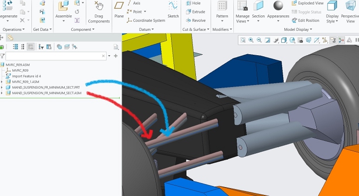
Regarding the CAD, position error:
It became clear that we are missing something very important in our rules. Just like the FIA writes rules in French and English, they define which is the relevant version in case of issues.
We supply three different pieces of CAD: We have the stp assembly, separate step files and stl.
I know, there are other views on this, but the common sense default version in this case is stl.
Why is that? The step versions cannot be, because OpenFOAM requires stl. Stl is a discretized version of the step files. As there are many different ways to create the stl (different algorithms and parameters), having this supplied version, created by MVRC, of the mandatory geometries, is the standard we need to follow.
And this is in your best interest, as it means you can run your simulations with the same conditions as the official ones are.
Sadly this is a bit unfortunate because, this time there was an unintended translation of the geometries between assembly to separate parts. This is what we will have to fix. But fix or no fix, the stl files are and will always be the ones to go by. We will also mention this in the technical regulations to avoid any misunderstandings in future.