How is the engine/gearbox assembly mounted to the tub?

All that has to do with the power train, gearbox, clutch, fuels and lubricants, etc. Generally the mechanical side of Formula One.
User avatar
747heavy
24
Joined: 06 Jul 2010, 21:45

Re: How is the engine/gearbox assembly mounted to the tub?

Post

not 100% related to this thread, but some informations and advice about bolted joints can be found here:
"Make the suspension adjustable and they will adjust it wrong ......
look what they can do to a carburetor in just a few moments of stupidity with a screwdriver."
- Colin Chapman

“Simplicity is the ultimate sophistication.” - Leonardo da Vinci

User avatar
PlatinumZealot
550
Joined: 12 Jun 2008, 03:45

Re: How is the engine/gearbox assembly mounted to the tub?

Post

I think anybody who has designed anything before knows that with metals, you have a relatively huge margin to play with when it comes to thermal expansion. The expansions are so small, you can often neglect them in most cases.
Especially when the material is taking simple loads and is stationary. Easy cheezy, make the object strong enough to take the negative strain. That is just basic strength of materials.

Take a look at a street car brake disk as another example. Or a street car cat iron exhaust manifold bolted to an aluminum head, even an Iron block engine bolted to an aluminum head. It's a no brainer.
🖐️✌️☝️👀👌✍️🐎🏆🙏

marcush.
159
Joined: 09 Mar 2004, 16:55

Re: How is the engine/gearbox assembly mounted to the tub?

Post

and because of that a unknown quantity of cars had issues with loose wheels this season...
please forgive ,i could not resist....

the problem with the tub interface was related to the assumption the engine was alumium and the tub was carbonfibre (wich is not expanding with temps).No doubt the carbonfibre structure will not stop the engine from growing,or would it?

User avatar
Redstorm
0
Joined: 24 Feb 2010, 12:07

Re: How is the engine/gearbox assembly mounted to the tub?

Post

The engine will flex, theres nothing the CF can do to stop it. However, as said above the rate of expansion may be very small. It could be as simple a fix as machining the bolts with an involute that will distort the amount of said expansion. Let the bolts take all the flex without compromising the tub.

User avatar
PlatinumZealot
550
Joined: 12 Jun 2008, 03:45

Re: How is the engine/gearbox assembly mounted to the tub?

Post

Redstorm wrote:The engine will flex, theres nothing the CF can do to stop it. However, as said above the rate of expansion may be very small. It could be as simple a fix as machining the bolts with an involute that will distort the amount of said expansion. Let the bolts take all the flex without compromising the tub.

Sorry but If you mean the carbon fibre cannot reduce the expansion of the aluminum block, that is nonsense. You can restrain an expanding object quite easily.

The restricted expansion will be taken up by the material as strain energy.

Again, here is a BMW S14 engine, the block is cast iron and the head is Aluminum, so make it it what you will.

Image
🖐️✌️☝️👀👌✍️🐎🏆🙏

marcush.
159
Joined: 09 Mar 2004, 16:55

Re: How is the engine/gearbox assembly mounted to the tub?

Post

Not quite ...CF has zero expansion factor with rising temp ,alumium 23,ferritic steel 11-15...The engine block is not that much hotter than the head.So the factors are matching better + the delta in temp is smaller...

User avatar
ringo
225
Joined: 29 Mar 2009, 10:57

Re: How is the engine/gearbox assembly mounted to the tub?

Post

marcush. wrote:Not quite ...CF has zero expansion factor with rising temp ,alumium 23,ferritic steel 11-15...The engine block is not that much hotter than the head.So the factors are matching better + the delta in temp is smaller...
So why dont you admit that it can be restrained? Aluminum to steel is still twice the expansion no matter the delta t.
There are no factors that match better, i don't know of any other factors.

A tear in the space time continuum doesn't form when a hot slug of metal is compressed in a forge. I don't see what is so blasphemous in restraining or oppressing thermal expansion?

[youtube]http://www.youtube.com/watch?v=20TJWA0srko[/youtube]
For Sure!!

User avatar
PlatinumZealot
550
Joined: 12 Jun 2008, 03:45

Re: How is the engine/gearbox assembly mounted to the tub?

Post

marcush. wrote:Not quite ...CF has zero expansion factor with rising temp ,alumium 23,ferritic steel 11-15...The engine block is not that much hotter than the head.So the factors are matching better + the delta in temp is smaller...
I can post a few questions from a text book if you wish. :wink: Trust me on this one.. its like saying the grass is green, and a sunny sky is blue.

here is an example from some random website:
The degree of restraint against thermal expansion, which every concrete member will undergo as its temperature increases, and the degree of continuity provided by the structural system at the supports, will also affect fire resistance.13 Both are generally regarded as being beneficial insofar as concrete members are concerned. Restraint against expansion, illustrated in Figure 4a, sets up additional compressive stresses which, when accounted for in the design, reduce the tensile forces that are initially resisted by the reinforcing steel in the bottom half of the member. Continuity (Figure 4b) enables a certain amount of stress redistribution to take place before excessive rotation develops at the supports and midspan, causing the collapse of the assembly. In a statically determinate (simply-supported) structure (Figure 4a), excessive rotation need only occur at one point (usually midspan) for failure to occur.
Image


Here is another one, this time two widely different materials and layouts:
If the structural member is axially restrained against displacement (as a column is), the expansion due to heat will be translated into thermal stresses that will increase the overall stress level in the member and cause an earlier collapse. Without axial restraint, a steel member will expand and could set up eccentric loading of adjacent structural members by displacing one of their ends (for example, a beam displacing the top of a column or of a load bearing masonry wall), as illustrated in Figure 6. Good fire protection engineering dictates that either thermal expansion be prevented by limiting steel temperatures, or its effects on the structure be accommodated in the design.
Image
🖐️✌️☝️👀👌✍️🐎🏆🙏

bew79
0
Joined: 20 Apr 2008, 03:17

Re: How is the engine/gearbox assembly mounted to the tub?

Post

there is discussion about the method used to bolt the engine to the tub, regardless of the method used, it must have changed/improved significantly over recent years as I don't recall seeing a tub/engine separate in an accident for quite some time. That sort of damage was not that uncommon in the past following a big shunt.

User avatar
Redstorm
0
Joined: 24 Feb 2010, 12:07

Re: How is the engine/gearbox assembly mounted to the tub?

Post

n smikle wrote:
Redstorm wrote:The engine will flex, theres nothing the CF can do to stop it. However, as said above the rate of expansion may be very small. It could be as simple a fix as machining the bolts with an involute that will distort the amount of said expansion. Let the bolts take all the flex without compromising the tub.

Sorry but If you mean the carbon fibre cannot reduce the expansion of the aluminum block, that is nonsense. You can restrain an expanding object quite easily.

The restricted expansion will be taken up by the material as strain energy.
Perhaps I should have chosen my words more carefully..... I did not mean that the engine will still flex the same as it would in any other state, CF be damned. I meant that expansion will still occur, and possibly the best solution would be to make the cheapest, easiest work around, I.E. bolts designed to absorb the expansion.

(Sorry, Im just the dumb grunt on the floor that machines what you guys design. Im not quite up to speed on the technical jargon just yet. Hope to add an eng. deg. soon.....can I borrow that book n smikle? :D )

User avatar
PlatinumZealot
550
Joined: 12 Jun 2008, 03:45

Re: How is the engine/gearbox assembly mounted to the tub?

Post

Yes, but the strength of the material can do the work for you. If the material is not strong enough or it's showing too much deflection then you can change the material to stronger one, and if that options is too expensive or if that doesn't work then you can go into designing for expansion. This case is very rare for most applications. If you are dealing with high temperature applications (where the strength of the material reduces drasticaly, usually over 300/400*C) and moving(vibrations) and cycling/fatigue that is where you go into your creep strength, S/N curve etc and maybe thickness optimization, changing materials, even cooling methods and whatever it takes to prevent failure.

I don't think a paltry 100*C engine to say 50*C carbon fibre plate is worth any effort. The expansion is just too small.

So basically the simplest "caveman" approach first then you go into complexities.
🖐️✌️☝️👀👌✍️🐎🏆🙏

marcush.
159
Joined: 09 Mar 2004, 16:55

Re: How is the engine/gearbox assembly mounted to the tub?

Post

Image

borrowed this from 747 h post in the 2013 engine thread ..what is going on there?

riff_raff
132
Joined: 24 Dec 2004, 10:18

Re: How is the engine/gearbox assembly mounted to the tub?

Post

marcush,

That's a Champ car engine. Notice the turbo inside the bell housing?

The tub is composite. But the rear bulkhead the engine mounts to is an aluminum plate.

riff_raff
"Q: How do you make a small fortune in racing?
A: Start with a large one!"

User avatar
humble sabot
27
Joined: 17 Feb 2007, 10:33

Re: How is the engine/gearbox assembly mounted to the tub?

Post

747heavy wrote: but all allow for a degree of expansion/movement between the disc and the bell. But a brake disc fixing is, IMHO, not a good comparsion for the problem at hand.

Nevertheless it usually does cater for the difference in the ETC of the materials involved, at least in racing brakes, where delta T is high (in case of the carbon brakes up to 1000K at peak load).
Which is may not the case for mountain bikes, scooters or light FWD car rear brakes.
It's high enough even in some mountainbike applications that something similar has been implemented. Though it is cost prohibitive. In any case the purpose in brakes is to keep the rotors running true and round. if held too tightly the stresses on the rotor have the habit of deforming it leading to all sorts of crappy brake behaviour.

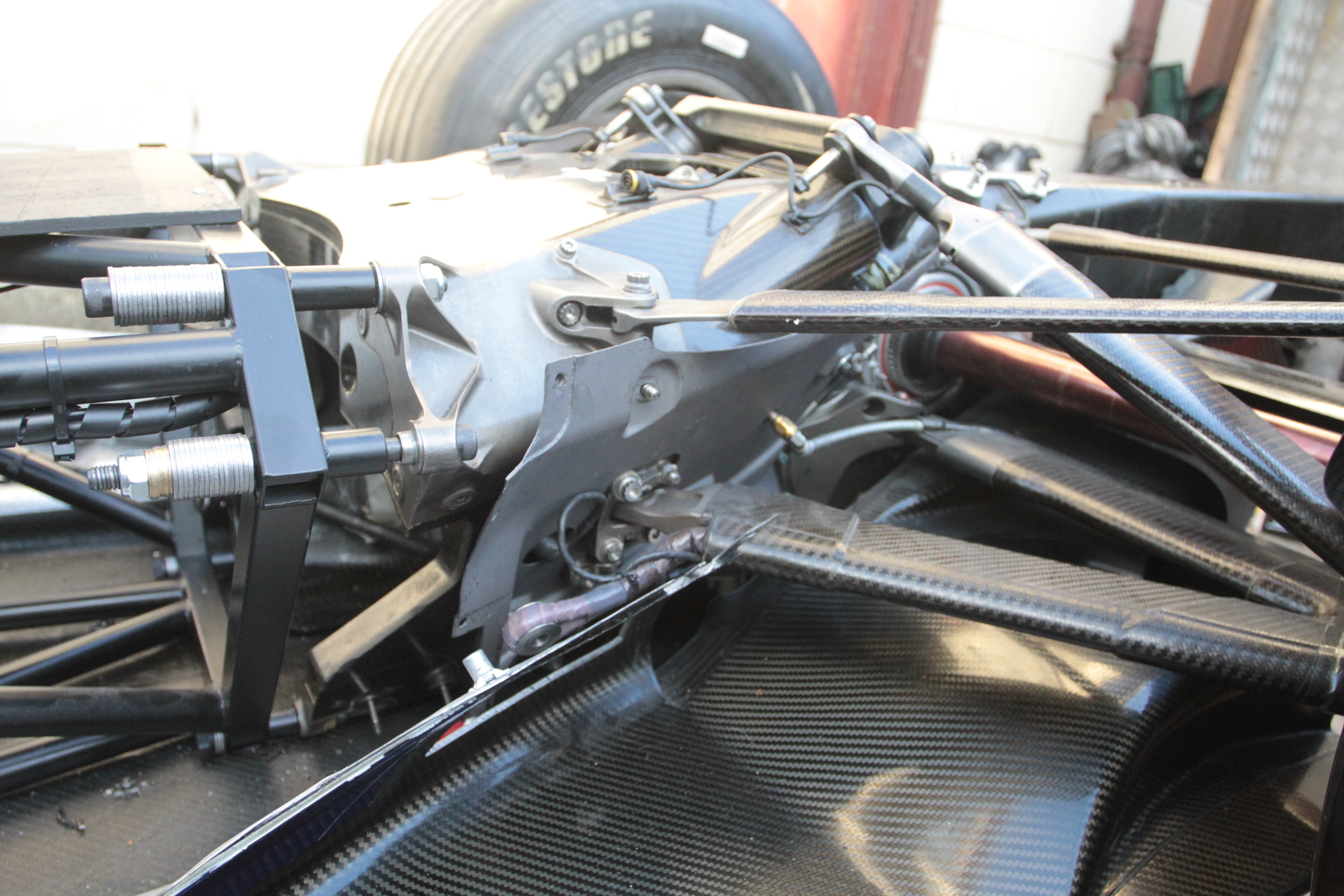
while in our case we're trying to prevent the carbon fiber tub from being destroyed in its efforts to hold the engine in place. But i feel you guys are neglecting a great big built in point of flexure. While it's worth going over the flexure behaviour of the studs it's a lot less of an issue than you may have realized. you guys sort of just swooshed past the picture that matters most. It's not the engine side. As you've all stated quite correctly the aluminium structure will expand some, I would posit that the geometry engine side is a bit too complicated to completely reverse engineer to figure out its degree of expansion, even if we have a rate to work with. NO what you should have been looking at all this time was the firewall. Guuys, it's (atleast since the introduction of the front mounted oiltank) an unconstrained U shape. It provides negligible resistance to the outward expansion of the engine, it is your point of flexion you've been arguing in circles over. The argument that the carbon won't expand is completely and utterly trumped by the macro geometry of the carbon part which in the axis in question is really not very stiff at all.
On top of that, in F1 the fatigue and fretting points are not going to turn into issues. Within reason, if the dowel will hold the machine together five races (and in many cases the dowels themselves are designed to be replaceable) you should be fine.


but that does leave an interesting question that was mooted earlier: namely the behaviour of the aluminium honeycomb in such a warm environment.


@ also in response to bew79, my understanding is that the separation had been designed in, reduce the mass the driver carries as he's tumbling through the air and you reduce the impact forces on his safety structure. And allowing it to break off on the initial impact also absorbs some energy.

the champcar issue seems much simpler, the carbon flexes outwards pushed by the firewall plate. This should lie well within the safety boundaries of the carbon's properties.
the four immutable forces:
static balance
dynamic balance
static imbalance
dynamic imbalance

Richard
Moderator
Joined: 15 Apr 2009, 14:41
Location: UK

Re: How is the engine/gearbox assembly mounted to the tub?

Post

These are the mounting points on the Honda R2007-5

Image

Image

Post Reply