nope, check againringo wrote:still in breach.
1 standard section in the middle 250mm. This is another section.
- Login or Register
No account yet? Sign up
nope, check againringo wrote:still in breach.
1 standard section in the middle 250mm. This is another section.

this is for the wing supports. But if a horizontal section for the 250mm area is taken your flex wing part will be included in it, making it 4 sections instead of 2.3.7.2 Any horizontal section taken through bodywork located forward of a point lying 450mm forward of the front
wheel centre line, less than 250mm from the car centre line, and between 125mm and 200mm above the
reference plane, may only contain two closed symmetrical sections with a maximum total area of
5000mm2
The thickness of each section may not exceed 25mm when measured perpendicular to the car .
centre line.
I guess that's up to you to balance the cross sectional areas of your wing profiles, and try to get enough area between the 2 to provid enough aerodynamic influence and strenght.3.7.4 In the area bounded by lines between 450mm and 1000mm ahead of the front wheel centre line, 250mm
and 400mm from the car centre line and between 75mm and 275mm above the reference plane, the
projected area of all bodywork onto the longitudinal centre plane of the car must be no more than
20,000mm2
This adapter will more than likely have to supported rigidly by both red and blue parts of the wing. Increasing the flat area of the blue part may help.The load will be applied in a downward direction using a 50mm diameter ram to the centre of area of an adapter measuring 300mm x 150mm, the 300mm length having been positioned parallel to the car centre line. Teams must supply the adapter when such a test is deemed necessary
this can be applied anywhere 450mm forward of the rear wheels, such as the wing.3.17.2 Bodywork may deflect no more than 10mm vertically when a 500N load is applied vertically to it 450mm
forward of the rear wheel centre line and 650mm from the car centre line. The load will be applied in a
downward direction using a 50mm diameter ram and an adapter of the same size. Teams must supply the
latter when such a test is deemed necessary
3.17.8 In order to ensure that the requirements of Article 3.15 are respected, the FIA reserves the right to
introduce further load/deflection tests on any part of the bodywork which appears to be (or is suspected of),
moving whilst the car is in motion.
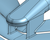
Both the red and the blue are effectively cantilever's... if they had the same construction then yes, the red looks like it would stiffer, but we don't know how Lengendary would intend on making these two sections do we? You can't take an F1 car at face value, you know that!Ringo wrote:...that blue part most definitely will be weaker than the red section of wing due to it's crossectional area and the fact that it's a cantilever.

...which we know they are... at the moment... look at the Red Bull situation.ringo wrote:Yeah they could get away with it...If the tests are taken literally.
Don't even start.machin wrote:...which we know they are... at the moment... look at the Red Bull situation.ringo wrote:Yeah they could get away with it...If the tests are taken literally.
I was talking about the RB6... it ran in its original flexy configuration for at least one race before the FIA changed the load tests.... hence why I think you might get away with it for one race..... the RB6 also wasn't illegal... it passed the tests which is why the tests then changed (although personally I don't see what's wrong with flexy bodywork, as long as it doesn't break).It's not illegal, nor is it the reason the RB7 is a good car.
3.7.2: yes it meets that:ringo wrote:this is for the wing supports. But if a horizontal section for the 250mm area is taken your flex wing part will be included in it, making it 4 sections instead of 2.3.7.2 Any horizontal section taken through bodywork located forward of a point lying 450mm forward of the front
wheel centre line, less than 250mm from the car centre line, and between 125mm and 200mm above the
reference plane, may only contain two closed symmetrical sections with a maximum total area of
5000mm2
The thickness of each section may not exceed 25mm when measured perpendicular to the car .
centre line.
But i assume you place the wing part outside of the 250mm to dodge this ruling.
Then this one is to be applied:I guess that's up to you to balance the cross sectional areas of your wing profiles, and try to get enough area between the 2 to provid enough aerodynamic influence and strenght.3.7.4 In the area bounded by lines between 450mm and 1000mm ahead of the front wheel centre line, 250mm
and 400mm from the car centre line and between 75mm and 275mm above the reference plane, the
projected area of all bodywork onto the longitudinal centre plane of the car must be no more than
20,000mm2
So maybe you got around the rules. However here's the downside; that blue part most definitely will be weaker than the red section of wing due to it's crossectional area and the fact that it's a cantilever.
If 100kg is placed on it, it more than likely will touch on the red.
But not only that, there is a very big adapter that you must provide to pass this test.This adapter will more than likely have to supported rigidly by both red and blue parts of the wing. Increasing the flat area of the blue part may help.The load will be applied in a downward direction using a 50mm diameter ram to the centre of area of an adapter measuring 300mm x 150mm, the 300mm length having been positioned parallel to the car centre line. Teams must supply the adapter when such a test is deemed necessary
then there's this test:this can be applied anywhere 450mm forward of the rear wheels, such as the wing.3.17.2 Bodywork may deflect no more than 10mm vertically when a 500N load is applied vertically to it 450mm
forward of the rear wheel centre line and 650mm from the car centre line. The load will be applied in a
downward direction using a 50mm diameter ram and an adapter of the same size. Teams must supply the
latter when such a test is deemed necessary
So that's it i guess if you pass those, then you got a good loop hole to the flexi wing. But If I were carrying out the tests, i would find it necessary to test the red parts.3.17.8 In order to ensure that the requirements of Article 3.15 are respected, the FIA reserves the right to
introduce further load/deflection tests on any part of the bodywork which appears to be (or is suspected of),
moving whilst the car is in motion.


It's slightly ironic that you only have time to work on your car when you're NOT on holiday.I can't really work on the car, and get on the internet easily this week because im on holiday

The blue bit is what undergoes the load test, so it is really stiff. The lower red part doesnt have to undergo a load test, so it can be made to flex easily.Tozza Mazza wrote:Hi legendaryM, I was inspired by your flexi wing, but thought that your concept was confusing. On my model thread (viewtopic.php?f=6&t=9807&start=15) I have also got a flexible front wing, however mine works so that the top section, in your case the blue section is flexible. The downforce created on the end of the blue section would effectively mean that the system works like a lever. The endplates below it are exactly 20mm below it so that it passes the flexible test. I don't really grip you're concept, as i don't see how the red section would be flexible. An explanation would be fantastic.
Tom.
For the first one, i assume you mean adding rake to the car, which i admit i hadn't done before but i have now on the very large update im gonna post soon. On your second point, i disagree with you, a double diffuser works by increasing the exit area of the diffuser. It has holes in the floor not above it.Jentel wrote:Hi,
i am fascinated of your great aerodynamic work!
Especially you Frontwings are very good!
I have also many aerodynamic ideas and drawings. And now i can copy some thinks
But also i want to say some mistakes on your F1 car.
First one: Your underbody is on one level to the ground. But he must be higher to the rear to work like a diffusor.
http://www.speed-magazin.de/Image/Forme ... rcedes.jpg
Secound think: You Diffusor. In my opinion you Diffusor can not work effectively because you send air under your Diffusor. But its wrong, because there must be a hypotension (under pressure).
On this way the double diffusor works. (Because of my bad english ists hard to discribe.) He takes air from the ground on the top of the diffusor to greate a hypotension (under pressure). Its a very nice physical effekt.
If you want, i can send you some pictures of my F1 car.
But at least, i want to say that your work looks great !!!!
keep on
(SORRY for my english, but its not my motherlanguage)