Calculating suspension/chassis loads

Here are our CFD links and discussions about aerodynamics, suspension, driver safety and tyres. Please stick to F1 on this forum.
Jersey Tom
166
Joined: 29 May 2006, 20:49
Location: Huntersville, NC

Re: Calculating suspension/chassis loads

Post

fastback33 wrote:This is the first time, i've even tried to design a suspension system, so thanks for bbearing with me guys. Is there any possible case where the loads going into the tires can increase the loading into the suspension links, by a serious magnitude? I would think not, but, nothing is ever impossible.
You've completely lost me...
Grip is a four letter word. All opinions are my own and not those of current or previous employers.

User avatar
Rideway
0
Joined: 12 Sep 2009, 13:31
Location: UK

Re: Calculating suspension/chassis loads

Post

I've just visited this topic and wanted to make sure i got it right. Not calculating all the moments created and in static situation (no loads transfer)... is this calculation right??
Image
Thank you very much

PS1. Obviously first equation is sumatory of all horizontal forces and for the second one the vertical forces..
PS2. Sorry about the quality, i've just done it with paint... as you can clearly see :oops:

The_Man
0
Joined: 15 Mar 2009, 11:59
Location: Mumbai India

Re: Calculating suspension/chassis loads

Post

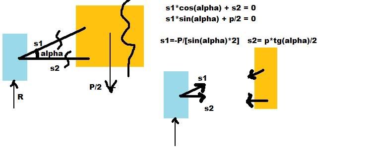
Rideway wrote:I've just visited this topic and wanted to make sure i got it right. Not calculating all the moments created and in static situation (no loads transfer)... is this calculation right??
Image
Thank you very much

PS1. Obviously first equation is sumatory of all horizontal forces and for the second one the vertical forces..
PS2. Sorry about the quality, i've just done it with paint... as you can clearly see :oops:
I really wish it where so simple. Unfortunately it is not.
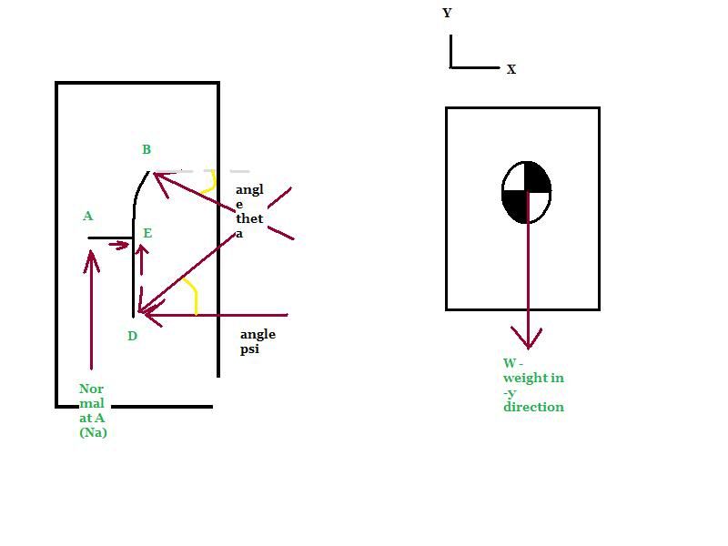
All the forces do not go through the push rod and the lower wishbone as you might suggest from the diagram. There is the upper arm, That will take some forces and also the tie rod has to be put in the mix.

For example it is not necessary that R is acting at the same point where s1 and s2 intersect(say D). It fact that is rarely the case. So taking moments about D, there will be nothing to balance out the R there fore we need another s3 in form of the upper control arm.

A similar thing will happen in the side view and you'll need a tie rod to satisfy moments about the king pin axis.

Mahek Mody
IIT Bombay Racing
Vehicle Dynamics FSAE 08; FS 09

User avatar
Rideway
0
Joined: 12 Sep 2009, 13:31
Location: UK

Re: Calculating suspension/chassis loads

Post

Thank you very much, dont know why i forgot about the upper wishbone. about the moments i knew that it was something like that, but i thought i could ignore in order to just calculate axial loads.
Thanks!

fastback33
0
Joined: 29 Aug 2007, 08:45

Re: Calculating suspension/chassis loads

Post

I want to revisit this topic for a bit.

I have recently been reviewing a simple statics analysis, and have hit a snag....

Assuming you know the weight of the vehicle and the normal force acting at the hub or the contact patch, you then come up with your three equations (lets assume for the right side):

A couple notes. the upper control arm point can be called point "B" the lower control point is "D" and the point where the spindle meets the upright is "E".

Let's just assume that the lower control arm is parallel to the ground and the top control arm is at some angle theta. Also that the pushrod is at an angle psi.

The positive x direction is to the right, and the positive y is "up" on the page.

so solving in the x:

ΣFx = -FBcos(theta)+ FEx+ FD + FDx cos(psi)=0

Solving in the y direction:

ΣFy = NA - .5W- FDsin(psi)+ FEy+ FBsin(theta)=0

Now, point E where the spindle and upright are mated through bearings has two unknowns as well as point D the lower control arm point. I chose to sum my moments about E.

Summing moments about E:

ΣME = -FDx(rdey)- FDcos(psi)(rdey)- FC(rcex)+ FBcos(theta)(rbey)+ FBsin(theta)(rbex)- .5W(.5track)+ NA(raex)

the r values refer to the distance from that point to the point where the moments are summed with the scalar direction given at the end.

Now this is my question. 1. Can someone check my work, this is probably the most important part of engineering and I would like to not screw it up.

2. I made the assumption that the spindle and the upright are two seperate components, and that the reaction forces at the bearings are external forces. Should I assume that the upright and spindle are all one "piece" essentially? I've tried solving this quarter of the car by hand and realize that I have too many unknowns.

Anyone care to shed some light as to my mistake? I'd really appreciate a fresh set of eyes.

P.S. uploading a pic proved rather difficult hence why I typed it instead of showing a picture....
Thanks for your time!

P.P.S. I realize this is fairly elementary for some of you and I feel that this is probably easier then i am making it, but I would like to get this right.

Jersey Tom
166
Joined: 29 May 2006, 20:49
Location: Huntersville, NC

Re: Calculating suspension/chassis loads

Post

Picture would really help!

photobucket.com
Grip is a four letter word. All opinions are my own and not those of current or previous employers.

fastback33
0
Joined: 29 Aug 2007, 08:45

Re: Calculating suspension/chassis loads

Post

Image

here you go, kind of crappy but don't have access to a scanner at work. I have a feeling I should assume the spindle and upright are one piece maybe? otherwise I have too many unknowns....

Jersey Tom
166
Joined: 29 May 2006, 20:49
Location: Huntersville, NC

Re: Calculating suspension/chassis loads

Post

No reason to worry about A or E. Assign a force (vertical and lateral components) at the tire footprint.. and resolve how they are carried in the control arms. The crap in between doesn't really matter.
Grip is a four letter word. All opinions are my own and not those of current or previous employers.

fastback33
0
Joined: 29 Aug 2007, 08:45

Re: Calculating suspension/chassis loads

Post

Okay. Why? Are the wheel, to hub/spindle, to unpright forces, all assumed to be internal? I'm not trying to be argumentative, but how would I find the load on the spindle/hub assembly if you don't account for it initially? Granted if you do tell me these are internal forces it greatly simplifies the problem but, im just curious.

By the way thanks for your help tom! Mucho appreciato!

Jersey Tom
166
Joined: 29 May 2006, 20:49
Location: Huntersville, NC

Re: Calculating suspension/chassis loads

Post

I'm not entirely certain on what you mean by "internal" forces... but if I'm guessing correctly, then yes, all that stuff at the spindle/hub point is internal.

The suspension links are really only there to counter externally applied loads... the only external system load is at the footprint of the tire.
Grip is a four letter word. All opinions are my own and not those of current or previous employers.

User avatar
747heavy
24
Joined: 06 Jul 2010, 21:45

Re: Calculating suspension/chassis loads

Post

I think it depends from what you try to achieve.
The premise of the thread was suspension/chassis loads, and to calculate them you
can ignore the detailed load path inside your spindle/bearing/upright.

Now if you want/need to dimension your wheelbearings, then you can´t, and should choose a different model for your calculations. - IMHO

So far, I think, we where concerned with the forces coming from the tire CP feed into the chassis or not?
"Make the suspension adjustable and they will adjust it wrong ......
look what they can do to a carburetor in just a few moments of stupidity with a screwdriver."
- Colin Chapman

“Simplicity is the ultimate sophistication.” - Leonardo da Vinci

fastback33
0
Joined: 29 Aug 2007, 08:45

Re: Calculating suspension/chassis loads

Post

Ahh vacation is nice for once.

Anyways Back to this. Yes tom that is what I meant by Internal forces....


@ 747 - Well, im assuming you can find all forces (external/internal) with two steps the first being what we've deiscussed here, where you have 6 unknowns and 6 eqtns. Or in this quarter case you have your 3 unknowns etc...

Second - finding spindle bearing loads using your numbers from the first step.

If you have another solution im all ears!

nikhilsalunke610
0
Joined: 06 Oct 2017, 07:56

Re: Calculating suspension/chassis loads

Post

How can i calculate forces on my double wish bone suspension

Sent from my Redmi Note 3 using Tapatalk


Greg Locock
233
Joined: 30 Jun 2012, 00:48

Re: Calculating suspension/chassis loads

Post

Are your wishbones symmetric in plan view? Are they horizontal in front view? Where does your spring mount to? Do you know what a free body diagram is? What wheel loads are you thinking about?

I'm not trying to put you off, but you need to have thought about all those questions.