Brian, yep, have seen some seals, they resemble power-steering type square seals found in the column/rack valve bank around the torsion rod.
Thanks also, replied,
BG
- Login or Register
No account yet? Sign up


This sounds so incredibly cool for a garage project type thing, even though your resources seem to have pushed it past "garage" point.Brian.G wrote:Hello folks, I thought Id post this here as some maybe interested.
My intent is to find out all I can about this device by building a prototype.
My main goal is to see If I can build a reliable item. I have done as much research and thinking as I can for a few yrs. It is now time to build an actual item to start testing on.
Ill be designing and making everything in house. Its a pretty simple test jig really, imagine just one valve and parts cut from a head, thats what It will resemble.
Since NO information exists on these, it is the only way to develop one. Ive read all the usual stuff. I thought of buying one off DelWest for testing, but they dont supply anything, instead design from scratch for your needs, at a cost of around 300K.
Nobody is will to share Info either, which I guess is ok, Im sure they have signed a ton of NDAs.
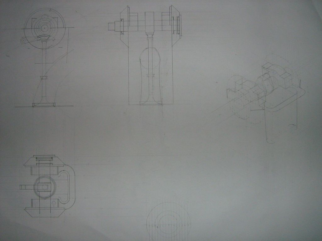
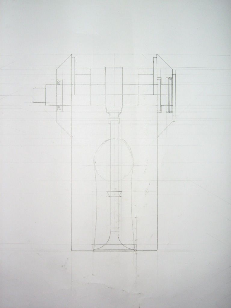
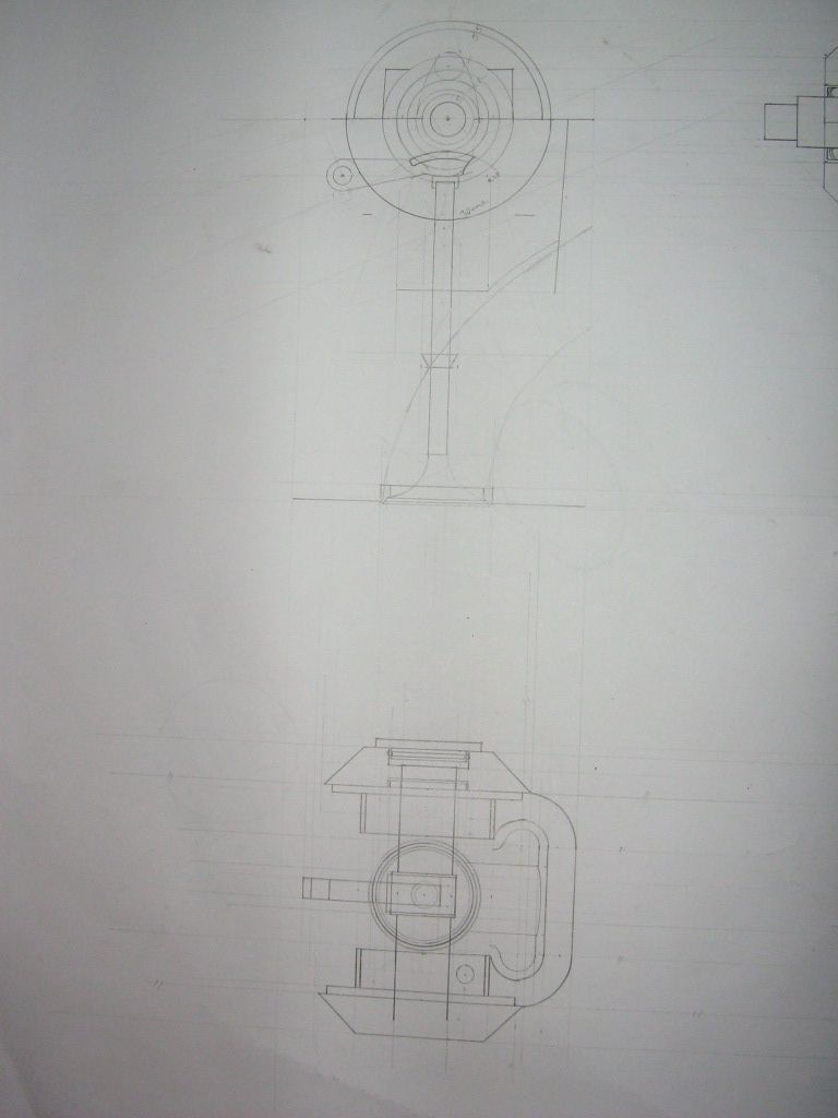
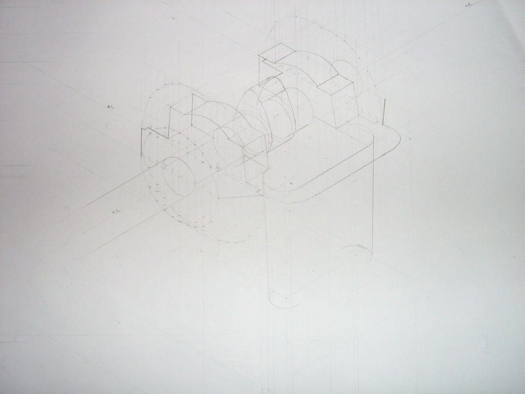
A fast rundown of the parts in mind.
A 40mm valve. Ill be turning this from Ti to have weights within what I hope to use later on. Its going to have a 7mm stem for the time being. I may waist it down in the port area for lightness.
The main body will be a cast housing.
The plunger will be Ti.
The piston housing will be an alloy sleeve, hard anodised in some xxxx spec I have to pick yet.
The finger follower will be steel. Im not putting that much design work into the follower geometry as yet, I simply want it to function. Although it will be designed in such a way as to prevent/minimise valve stem side loading.
Ill be cutting/grinding the cam also. The lift will be around the 15mm mark.
For the collet/retainer, I may make these, but Ive some on order from ducati which Ill look at first.
My target rpm is around 15-18krpm.
It will be oiled with an aux oil pump and assembly. Ill also probably heat the oil to around 120ish.
The guide will be silicon bronze of some sort.
My main concern at the minute, is getting some oil to the stem given that there is an 'air tight' seal there. But Ill figure it out in time. And also plunger galling to the bore walls.
I dont know how long its going to take, and I dont care, something to pass the time in the evenings right...
To view the valve contacting seat at high rpm, and to make sure its not bouncing Ill be monitoring it.
I haven't made up my mind just how yet, but its simple once I do so.
My options are
Stroboscope.
Proximity sensors coupled with an oscilloscope.
Fiber-optic interferometer.
Obviously these setups range in cost vastly, so perhaps Ill start with the strobe, and some for of macro viewing/capture device(camera)
Im doing all drawings and calculations on paper with pencils, so it takes a while. But, Im ok with drawing boards.
The reason for doing all the above is to develop a usable valve train for use in a single cylinder 4 valve test engine. This engine will have a bore of 98mm, and a stroke of 39.7mm. Target rpm is 15.5-16krpm.
I will use this to study a variety of things but mainly con-rod design, and journals.
The test engine is a while off, since I have only started drawing it about two months ago. You cant imagine all there is to think about in something that is technically a glorified lawnmower engine. But, Ill get there.
I hope it will interest some, as its what I wanted to do for oh...20yrs now...
Materials are not particularly dear either for the valve assembly, I cant even remember what they cost. The dearest thing is time, but thats free if its your own to pass.
Brian.G
Brian G. ?Martha39 wrote:Piston and seal at first, but Ill try anything until I reach my targets, no matter what it takes.
Based on a lot of studies, the technology needed is heavy, energy consuming, and would also feature a lot of mass at the top of engine, where you least want it in the line of coils and what not. Plus, from where I see it, if you want a really light armature(the valve) your control surfaces are limited by the diameter of the valve stem. If you do not want to use valve as armature, but instead drive from overhead with a larger armature, you still need a spring return in there someplace on the actual valve. That, or somehow connect the valve tip/lashcap to the end of the control armature - not easy.Nowhereman wrote:I admire the energy going into this prototype but, why not eliminate the cams too?
Lets go to an electromagnetic actuator built around the valve itself.
No camshaft, just a cpu that is montitoring the crank speed and position.
That will be more than fast and accurate enough to run any valve train at any realistic RPM level.

Wow, if the tooling costs 5k, the machine it's self is like what? 40k or more?Brian.G wrote:Digging this back from the dead, I am continuing in the new year. I had to park it, as without a cnc it made visualizing all my ideas into real form very tough. This was true for many of my prototype works.
Thankfully, due to a nice rise in my 'real work' last year, I have now purchased a cnc milling machine, complete with 5k in tooling. Its been a steep learning curve, as I wasn't familiar with cncs, or infact cam before this, other than pointing at paths and drawings and telling others to 'change here', or 'do this first' but both myself, and the cnc mill are now flying it in terms of making things.
Before I can start, I just want to finish up my self built 4+5th axis so Ill be as free as a bird in machining terms.
The fact that I can cast parts, and also cnc mill now opens up possibilities greatly.
Thanks all, Happy Christmas, and have a great new year whatever it holds.
Brian,