Front Wing Flow around Wheels

Here are our CFD links and discussions about aerodynamics, suspension, driver safety and tyres. Please stick to F1 on this forum.
hardingfv32
hardingfv32
35
Joined: 03 Apr 2011, 19:42

Front Wing Flow around Wheels

Post

Is there a general consensus that the 2012 front wing endplates route flow to the outside of the front wheels?

This is a study of a proposed 2010 compliant front wing. There does not seem to be the slightest sign of flow being directed to the outside of the front wheels. Looks more like an effort to form vortices. I know the current end plates are more extreme, but are we certain they are actually routing flow around the outside of the front wheels?

Brian

Image

http://www.behance.net/gallery/F1-front ... t)/3908191

bhall
bhall
244
Joined: 28 Feb 2006, 21:26

Re: Front Wing Flow around Wheels

Post

Something tells me the lack of wheels has skewed the simulation a bit. That is, unless insanely porous tires are on the horizon. (I bet Pirelli could make those --- degrade real quick.)

At any rate, because I'm nothing if not benelephant...
McCabism wrote: Aerodynamic wheel-wing interaction

In 2007 Martinus van den Berg published a PhD thesis on the interaction between a rotating wheel and an inverted wing. The research was sponsored by the Honda F1 team, which has, of course, evolved into the Mercedes F1 team; the same team responsible for the 2012 front-wing F-duct.

The most interesting conclusion of van den Berg's research was that the front-wheel drag is greater at high front-wing ride-heights than it is at low ride-heights.

Image
Figure 1: High ride-height, high wheel drag

Previous research conducted by James McManus (who was snapped up by McLaren before completing his PhD) had identified that the flow field of an isolated rotating wheel contains an arch vortex in the upper region of the near wake (E and F in Figure 1), and a pair of counter-rotating vortices in the lower, ground-level region of the near wake (H and I). There is also a bow wave (D) created by the upstream side of the contact patch.

When an inverted wing equipped with an endplate is placed in front of such a rotating wheel, van den Berg identified three further primary flow features: a vortex from the upper edge of the endplate (A); a vortex from the junction between the trailing edge of the flap and the endplate (B); and a vortex from the lower edge of the endplate (C).

With a 50% scale 580mm front wing-span (relevant to pre-2009 F1 regulations), van den Berg identified that the top edge front-wing vortex passes over the crown of the wheel at high ride-heights (Figure 1), but passes inside the wheel at low ride-heights (Figure 2). At high ride-heights this vortex over the crown keeps the flow attached for longer, increasing the lift of the wheel, and creating a zone of re-circulation (G) behind the wheel, which increases the wheel drag:

"When this vortex...passes over the wheel it starts a strong interaction with the wheel vortex originating from the top of the wheel (feature “F”), the vortex originating from the flap trailing edge (TE) junction (feature “B”) and the lower edge vortex (feature “C”), accumulating in a strong circulation," (Journal of Fluids Engineering, October 2009, Vol. 131).

Figure 2 shows the flow field at a lower front-wing ride-height, where the top-edge vortex goes inside the wheel. In addition, it can be seen that both the bow wave to the inboard side of the wheel, and the inside leg of the counter-rotating vortex pair in the wheel wake, have been replaced by the vortex generated by the bottom-edge of the front-wing, which is strengthened in ground-effect.

Image
Figure 2: Low ride-height, low wheel drag

At first sight, this might seem to be inconsistent with the concept of the 2012 F-duct, which stalls the front-wing, and permits the front ride-height to increase, with the intention of reducing drag (and balancing front-rear downforce when the DRS is operated). One presumes, however, that the reason for this discrepancy is that the research was conducted with a narrow, pre-2009 front-wing, the endplates of which were on the inboard side of the wheel. Post-2009, with 1800mm wide front-wings, the endplates and the vortices they generate, lie upstream of the outer shoulder of the wheel. It may be that the top-edge vortex now goes outside the front-wheel at all front-wing ride-heights, and certainly the outward curvature of the front-wing endplates would achieve this.

One note of caution should be sounded here: the Figures reproduced above are obtained from steady-state simulations, whereas the actual flow in the wheel-wake tends to flap about in an unsteady manner, as close observation of the water droplets shed by the wheel in wet-weather conditions reveals. Flow features which appear to exist in a steady simulation are sometimes completely absent in the instantaneous flow fields of an unsteady simulation.

wesley123
wesley123
204
Joined: 23 Feb 2008, 17:55

Re: Front Wing Flow around Wheels

Post

I think it is quite obvious, take a look at a F1 front wing and see how the end plates turn to the outside
"Bite my shiny metal ass" - Bender

hardingfv32
hardingfv32
35
Joined: 03 Apr 2011, 19:42

Re: Front Wing Flow around Wheels

Post

While the wheel plays a major role in how the flow goes around the wheel, the first CFD image shows no indication of wing trying to begin or helping the process of flow around the outside of the wheel. You would think that the wing would initiate the early stages of this outward flow direction without the help of the wheel. 2010 was the second year of full width front wings, so the value of routing flow around the outside of the wheel would have been well studied by 2010. The end plate tested is representative of what was eventually used in 2010.

Brian

bhall
bhall
244
Joined: 28 Feb 2006, 21:26

Re: Front Wing Flow around Wheels

Post

hardingfv32 wrote:[...]

The end plate tested is representative of what was eventually used in 2010.

Brian
Are you sure about that? Frankly, I see very little in common between this digital representation and front wings that have actually raced. Moreover, not only does the model lack wheels - what isolationist thought that was a good idea? - it also shows no sign of flexing, which was/is a substantial factor in the end plate's ability to deflect air flow around the wheels, nor is it equipped with cascades.

I think this front wing is a Formula One front wing in much the same way Dame Edna is a woman.

Real wings:
Image
Image
Image
Image
Image

Each of those wings has so-called "outwash" end plates. In fact, this feature played a prominent role in Brawn's early success in 2009. The field didn't start catching up until they'd developed their own "outwash" front wings. That lets us know the loss of surface area associated with this feature is well worth the reduction in drag from the front wheels.

Image
BGP 001 (fast)

Image
MP4-24 (not so much)
hardingfv32 wrote:[...]

You would think that the wing would initiate the early stages of this outward flow direction without the help of the wheel

[...]
Why would one think that? Does it make sense to give the wing additional drag when you're just going to throw a heaping helping of drag right behind it anyway? Since you can't avoid it, might as well use it for something.

fastback33
fastback33
0
Joined: 29 Aug 2007, 08:45

Re: Front Wing Flow around Wheels

Post

I haven't had much time to spend learning aero effects and cfd and such. But, would it be worth while to create a sort of boundary layer around the wheels (this would create drag of course) that would somehow reduce the overall drag of the system?? Are there cases where people have done this? Created a more localized drag to reduce overall drag....

bhall
bhall
244
Joined: 28 Feb 2006, 21:26

Re: Front Wing Flow around Wheels

Post

I'm not sure what you mean by creating more localized drag to reduce overall drag. But, I do know that teams put some work into minimizing the drag caused by the funky wake caused by the wheels. The results worked so well they got banned.

Image
Image
Image

fastback33
fastback33
0
Joined: 29 Aug 2007, 08:45

Re: Front Wing Flow around Wheels

Post

I guess a better example is blowing the rear wing of the car. The exhaust creates a boundary layer no? Thus the freestream air has to flow around the exhaust gas and the wing. Again, im not an aero guru (yet) so im not sure if my concepts are plausible.

Or another way to think about it would be to create a bubble of air around the wheel/tire and then have something the free stream air has to flow around.

bhall
bhall
244
Joined: 28 Feb 2006, 21:26

Re: Front Wing Flow around Wheels

Post

Maybe this will help.
APS.org wrote:Racecars employ extremely sophisticated aerodynamic designs, paralleling the performance of highly efficient airplanes. The front and back wings easily produce enough force to lift the car off the racetrack. Instead they are mounted upside down which plants the car into the ground and increases its cornering speed. Fast laps are all about lift, not drag after all.

Formula 1 vehicles are the result of world-class engineers working around the clock studying the airflow in state of the art wind tunnels and on the fastest computers in the world. While airplane design has remained largely unchanged in the last 30 years, F1 engineers redesign cars for every race! Seemingly minor changes have the ability to separate podium finishers from the rest of the grid.

Image
Figure 1: Front view of a Formula 1 car showing the inboard brake ducts (highlighted by blue arrows) used to cool the brake assembly.

Due to the time constraints imposed by the racing schedule, Formula 1 teams routinely partner with academic institutions to dig deeper into the physics and answer fundamental questions concerning the airflow around the car. An example of this has been the collaboration between Toyota F1 and Stanford University. The Stanford group was asked to investigate the flow around an isolated tire to identify the dynamics of the flow structure in the wake, determine if computer simulations match experimental measurements and understand under which circumstances the flow becomes asymmetrical with respect to a vertical plane that cut the tire in half. In spite of the broad knowledge regarding the aerodynamics of bluff bodies, the flow distortion introduced by the tire rotation, the interactions between the rubber and the ground under load, the effect of the air captured and then released by the brake system, and, in general the uncertainties related to the unknown geometry of the tire, pose tremendous challenges to a complete understanding.

Image
Figure 2: Side view of Toyota TF109 front end showing the outboard stationary wheel cover highlighted by the blue arrow. (Photo Courtesy of Toyota Formula 1)

The airflow around Formula 1 racecars is dominated by the presence of massive, exposed tires. The performance of the engine radiator and the back wing are determined by the flow structures originating on the front tires and in their near wake. Moreover, the brake system requires active cooling and a complex set of inlets and ducts are carved within the wheel (see Fig. 1) to preserve the braking efficiency. During last year’s championship, wheel covers (see Fig. 2) emerged as a competitive advantage and were employed rapidly by all teams. What is their role? How effective are they in increasing the brake cooling? Can they alter the flow in the wake of the tire and, therefore, act as an aerodynamic device? These are the types of questions engineers routinely try to answer.

Image
Figure 3: Experimental rolling road facility at Stanford. The green light immediately behind the isolated Formula 1 tire is the Particle Image Velocimetry plane used to extract velocity vectors from the wake of the tire. Pictured here are Kin Lo (left) and Emin Issakhanian (right) who are PhD students working in John Eaton's group. (Photo Courtesy of Mechanical Engineering at Stanford).

The Toyota-Stanford collaboration, for the first time, aimed at a detailed experimental investigation (using Particle Image Velocimetry [1], Fig. 3) and high-fidelity simulation (using Large Eddy Simulation [2], Fig 4) of a realistic F1 wheel including the tire deformation and the entire brake duct assembly. The simulations were performed on hundreds of CPUs for weeks at a time, and provided a vivid representation of the wake airflow (see movies below) and the presence of highly coherent structures, leading to quantitative understanding of the time-scale associated to the motion.

Image
Figure 4: Large Eddy Simulation showing pressure contours 2 cm above the ground plane for an isolated stationary tire. The lighter green dots emanating from the contact patch of the tire are low pressure vortical structures.

Not surprisingly, the results of the LES simulations, confirmed by the PIV measurements, illustrate that unsteadiness, large-scale separation, and longitudinal vortical structures dominate the turbulent airflow behind the tire. The flow is very unstable and has the tendency to fluctuate from side to side. The results also show that there is a region of separated flow close to the back of the tire where air particles recirculate and travel forward faster than the car moves. Finally, the simulations show that a system of counter-rotating vortices overwhelms the wake of the isolated tire very far downstream. Additional simulations and experiments also confirmed the fundamental effect of tire rotation; specifically, the presence of a very strong downwash in the wake of a stationary tire which leads to only limited recirculation and thus to airflow that is not representative of realistic racecar conditions.

A large part of the research has been focused on determining the cause of the observed asymmetry in the strength of the counter-rotating vortices in the wake. The simulations show conclusively that the transverse flow determined by the brake system and, in particular, the flow exiting the outboard rotating spokes fundamentally alters the near wake structure. The air is sucked in by the brake inlet duct on the inboard side of the car, and spat out the outboard side of the car. As a result, the outboard vortex is reduced in size and displaced towards the ground, as illustrated in Fig. 5.

Image
Figure 5: Numerical simulation of a plane downstream of a rotating Formula 1 tire for the case where all passages inside the tire have been blocked off (left) and for the true configuration where airflow is allowed to travel through the wheel hub (right). When airflow is allowed to freely move inside the hub, air travels from left to right (inboard to outboard) increasing the size and intensity of vortex 'A'. As a result vortex 'B' is displaced closer to the ground and looses almost all of its intensity.

Finally, an important aspect of the simulation work was the quantification of the effect of geometrical uncertainties in the definition of the tire geometry. The aerodynamic load produces a deformation that is difficult to determine because of the extreme complexity of the interaction between the rubber and the road. Constructing a parametric model of the tire proved that the uncertainty in the contact patch geometry dominates the wake airflow only in the case of a stationary (non rotating) tire simulation.

For F1 racecars traveling at 200mph, the wheels are not just about the grip; understanding the airflow over the tire and inside the wheel plays an important role in keeping teams successful.

[youtube]http://www.youtube.com/watch?v=-E2XDdihxh4[/youtube]
[youtube]http://www.youtube.com/watch?v=UsuQVLx9lFY[/youtube]
[youtube]http://www.youtube.com/watch?v=bsQcPNCm0_8[/youtube]
[youtube]http://www.youtube.com/watch?v=YtGVQ1qAod8[/youtube]

hardingfv32
hardingfv32
35
Joined: 03 Apr 2011, 19:42

Re: Front Wing Flow around Wheels

Post

bhallg2k wrote: Does it make sense to give the wing additional drag when you're just going to throw a heaping helping of drag right behind it anyway? Since you can't avoid it, might as well use it for something.
I would think the point of trying to route flow around the wheel would be to reduce the drag the is normally created by flow hitting the wheel.

Brian

bhall
bhall
244
Joined: 28 Feb 2006, 21:26

Re: Front Wing Flow around Wheels

Post

But, that assumes the wheel doesn't have an upstream effect on the air flow around the wing.

I think cascade wings are implemented expressly for that interaction. I just don't know how to research it yet.

User avatar
Cam
45
Joined: 02 Mar 2012, 08:38

Re: Front Wing Flow around Wheels

Post

Superb info bhall2gk. +2
“There is only one good, knowledge, and one evil, ignorance.”
― Socrates
Ignorance is a state of being uninformed. Ignorant describes a person in the state of being unaware
who deliberately ignores or disregards important information or facts. © all rights reserved.

Just_a_fan
Just_a_fan
593
Joined: 31 Jan 2010, 20:37

Re: Front Wing Flow around Wheels

Post

Well, for a start, the student made the following statement:
At the time of the project (end of 2009) the new FIA's regulations for the upcoming racing season (2010) was not yet all disclosed and revealed (e.g. many technical drawing where missing on the regulation itself) so I had to work really hard also in the Regulation understanding & interpretation process)

The geometry as not been optimized due to a lack of time (as it can be seen in the 2d graphics results the flap stalls)..a better design should be evaluated.
So, he didn't know the regs properly and he admits that the geometry needs further work.

Looking at the chosen design:
Image
I would suggest that there is an indication of an outward flow endplate there. I also note how the aerofoil separation distances are far from representative of a real front wing. Also, as noted elsewhere in the thread, the lack of a rotating wheel behind the wing removes a major factor in the flow of air around the wing.

This piece of work definitely can not be used as a way of justifying a non-outward flow endplate. It's just too basic a piece of work (with all due respect to the student who has otherwise obviously worked hard on his thesis and I applaud him for that).

Back to the original issue - the current wide front wing suffers from the front tyre interupting the free flow from approx. 30-40% of the active downforce producing surface of the wing. Thus any wing / wheel interaction will endeavour to do 3 things:
1. reduce the lift experienced by the tyre as this is working against the downforce and reduces the net grip available
2. reduce the drag caused by the tyre
3. increase the extraction of air from below the front wing (sometimes called scavenging the flow).

The flow coming off the front wing can go three ways: outside the tyre, over the tyre, inside the tyre.

We have seen, in the paper quoted by bhallg2k, that flow over the front tyre increases front tyre lift and drag. This is obviously not a good choice.

Directing the flow inwards is shown to be beneficial in the paper but it must be remembered that the paper talks about the 2009 front wing (i.e. the short span wing). That wing placed the endplate approx. in front of the inner shoulder of the front tyre. It makes sense in that situation to direct the flow / vortices inwards of the tyre because otherwise you have to get sufficient energy in to the flow to turn it through approx. 80deg and get it across the moving face of the tyre. Look at the McLaren front wing of the period to see how they obviously designed the endplate to direct air inwards.
Image
The -23 is on the right. See how they sacrificed ultimate wing area to allow an inward turning endplate (which gave a large footplate too which is also probably beneficial to the overall efficency of the front wing).

So we are left with the option of turning the flow outwards around the tyre. Look at the current endplates and you see that they are designed to turn the flow outwards:
Image
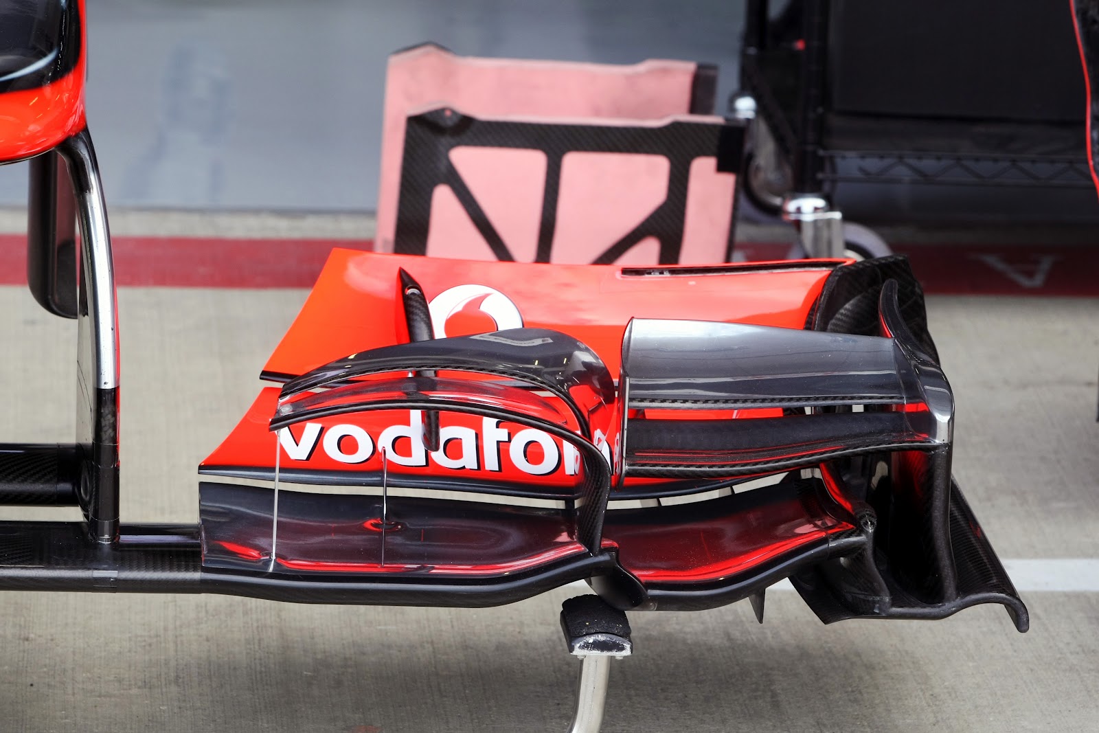
Indeed, looking at the current McLaren wing, it appears to me that the cascade wings on top of the front wing are, in part at least, designed to help the outward flow. Look at the inboard of the two cascades and you can see that the long radius bend has a long, heavily cambered, chord that appears to be trying to direct air outwards. The apparent close coupling of this section and the outer cascade suggests that the outer one is being used to help drive the turning effect of the inner cascade. The endplate itself is split in two with the main, inner section having a marked outwards bend to it. This will direct air outwards (as well as increasing the expansion of the volume below the outer most part of the front wing). Note also how the endplate has been brought inwards to give a large footplate again - this is obviously an important part of making the wing work effectively.

I think there can be little doubt that the current methodology is to turn the flow outwards around the front tyre.
If you are more fortunate than others, build a larger table not a taller fence.

hardingfv32
hardingfv32
35
Joined: 03 Apr 2011, 19:42

Re: Front Wing Flow around Wheels

Post

The FW in this study is the current full width style.

The 'External side End Plate' does look like it is curved/positioned for outside the wheel flow. Why is there no sign of that outward flow in the simulation? Is the bias of the main trailing vortex towards the center indicating some kind of effect from the end plate design?

In general, what is the purpose of this complex style of end plate: Flow routing, vortex generation, etc.?

Brian

Just_a_fan
Just_a_fan
593
Joined: 31 Jan 2010, 20:37

Re: Front Wing Flow around Wheels

Post

It's a full width wing, yes, but it is not at all representative of a current F1 wing because of the design of the elements and their relative positions. The wing also utilises formal inner endplates where current F1 cars do not generally do - they usually have tapered tips to the aerofoil sections. Also, the lack of a wheel behind the wing rather reduces the relevance of the indicated flow structures behind the wing.

There isn't a single vortex behind the wing (here being a set of three aerofoils set between a simple inner endplate and more complex outer endplate rather than the whole wing). There are two vortices, one each from the outer endplate and the inner endplate as you would expect. But there is no wheel modelled so they interact in a way that isn't at all representative of a real car - they are effectively drawn together in this model because each is a low pressure region relative to the free stream around them. As the inner endplate is simpler and appears to be less effective in reducing the inherent vortex, I would suggest that the inner vortex is stronger (has a lower pressure) than the outer vortex and hence the general trend is for the outer vortex to move towards the inner vortex - in this model.

On a car, the inner endplate vortex might be expected to travel between the wheel and the chassis and interact with one or a combination of, the flow under the the nose; the flow around the 'tea tray'; the flow around the barge boards; the flow around/behind the tyre. None of those is present here so those interactions are not modelled.

The vortex from the outer endplate would hit the tyre's shoulder/outer part of the tread. Again, the tyre is not present in the simulation so this interaction is not visualised.

As the inner endplate flow will travel as noted above, the outer endplate needs to deal with its vortex in order to reduce overall drag, reduce tyre lift, increase front wing effectiveness.

Now, which is the best way to deal with the vortex from the outer endplate? Send it outwards around the outer shoulder and then have a useful vortex to do work behind the tyre? Or try to send it inwards across the entire surface of the tyre and try to get it to flow off the tyre's inner shoulder and then be useful thereafter? I think the way I've framed that question points to the answer.

So, to answer your final question. You tell me: does the outer endplate route the flow? Generate a vortex? Both?

Hint: the answer is "yes" to each of those questions. And it also helps to improve extraction of air from below the wing in order to improve front wing downforce. By improving downforce and reducing overall drag the endplate improves the efficiency of the wing. And by careful design it should be possible to set up flow structures that have a beneficial effect on the rest of the car e.g. flow along the floor's edge, flow towards the exhaust/diffuser region etc. Indeed, these flow structures are very evident in the images posted by bhallg2k.
If you are more fortunate than others, build a larger table not a taller fence.