TERS : Thermal Energy Recovery System

All that has to do with the power train, gearbox, clutch, fuels and lubricants, etc. Generally the mechanical side of Formula One.
Post Reply
Wideband mindeD
0
Joined: 24 Aug 2012, 21:55

Re: TERS : Thermal Energy Recovery System

Post

aussiegman wrote:Putting the weight of a flywheel assembly on to the CHRA of the turbo will be extremely prohibitive in terms of weight, reliability, packaging, CoG, complexity as well as negatively affecting transient response and spool times for the turbine compressor assembly.
Please explain why. None of those reasons explain why, and we spoke of the inertial moments being damped/boosted by applying current at the right times.
There are already turbo CHRA's that incorporate an electric motor/generator that can produce electricity and then recover that to keep the compressor spinning. So all that is needed is a storage device.
Link? That would be awesome to read up on.
If William wants to use the separate flywheel storage system then it could be fed from a turbo CHRA generator as well as other systems such as the KERS brake recovery systems (where still legal).

The recovered energy can then be fed back to the CHRA motor and/or the KERS as needed.
Completely non-applicable to what I proposed.
The flywheel systems have a few advantages such as heat management, longevity, servicability etc (not always a huge concern in F1) and overall weight remains similar or lower than some battery solutions, especially as the allowable capacity increases.

However overall packaging as said is the biggest hurdle. As one homogeneous unit its weight cannot be optimised and it should sit on the centre line of the car for balance behind the driver, however this is where the fuel tank etc reside so compromises are required.

It could still be used as long as they can get an advantage in doing so over a bulky battery requirement as capacity increases or if limitations are placed on service life such as those that currently exist for engines and gearboxes etc (battery packs must last 5 races etc). I think it will depend on the weight of the unit vs storage capacity when compared to a similar sized battery solution with similar capacity and longevity.
Once again, I am not talking about a seperate KERS unit or storage, just a MMC/electromagnetic coil flywheel as a means of applying and removing energy from the prop shaft while in the same rotational axis. The weight would be less than 1 kilogram, and depending on where you mount the turbo, the COG argument is not really admissable.

Maybe they just dont need that fine of a control over the prop-shaft speed?

Tommy Cookers
617
Joined: 17 Feb 2012, 16:55

Re: TERS : Thermal Energy Recovery System

Post

can we agree that. in principle, the MGUH functionality ........

can be integrated with the turbo, ie coaxial 1:1 drive
or driven by the turbo coaxially but geared (likely a speed reduction?)
or driven (by the turbo) on some other axis displaced by some gear etc train (likely a speed reduction?)
(and won't be realised with a device that weighs 1 kg!)

MGUH and turbo together have significant inertia (and will to that extent store energy mechanically whatever the rules say)
in principle we could design for minimal (or maximal) inertia, gearing is a major factor in this
(direct drive MGUH would be long but small dia for best response as M and G,running at turbo rpm seems problematic anyway)

(mechanical) clutching the MGUH is not allowed ??? (similar functionality can/will be achieved electrically)

the recovered power useage limit is to be 120kW
surely this suggests more instantaneous useage of recovered energy rather than much greater storage ?
(much energy can/will ? be recovered and used instantaneously ie electric compounding)
surely the fuel rate rule will be tightened year-by-year ?

IMO fine control of cylinder filling is needed eg as rpm increases 16% without any fuel increase - this is unprecedented
(to avoid turbo delivering more air than is useable(VG turbo banned), and for best use of CR/ER that is fixed by the VVT ban)
(rules allow electrical control of load on turbo to give exhaust pressure suitable for delivery at all rpm and to improve recovery from turbine, my Aug 16 post on the Formula 1 1.6 engines thread attempted to justify this 'part-time EGR' route)

a CR of 13:1 (possible with unlimited ON and high rpm) allows the 'free' recoverable power to be 11-12% additional to crankshaft power
(in principle this is independent of the above load/exhaust pressure modulation)

aussiegman
105
Joined: 07 Feb 2012, 07:16
Location: Sydney, Hong Kong & BVI

Re: TERS : Thermal Energy Recovery System

Post

Wideband mindeD wrote:Please explain why. None of those reasons explain why, and we spoke of the inertial moments being damped/boosted by applying current at the right times.
Have you actually ever seen the physical size of a complete flywheel unit such as these??

Image
Image

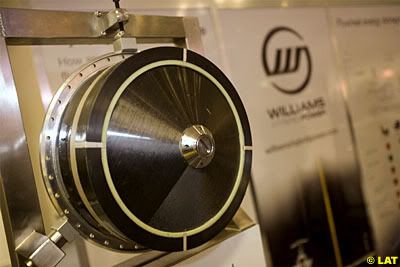
Now imagine this attached to a turbo CHRA, sitting above the gearbox and behind the engine. This might give you a sense of the issues in placing such a hybrid flywheel assembly physically onto the CHRA of the turbo. Some of the challenges and my thoughts are detailed below:

1: Due to the FIA regulation requirements, the weight of the flywheel assembly will be lifted in the chassis and at a higher CoG than is optimal;

2: The forces involved will require greatly increased support structures, resulting in an increase in weight, size and complexity. Also, there will be substantial increases in the CHRA for support structures, increasing its complexity, size and weight which will require greater cooling and lubrication capacity. This all negatively affects the CoG of the vehicle both in terms of height in the chassis and front to rear weight distribution as well as affecting packaging requirements;

3: Supporting the flywheel on the same shaft running through of the CHRA as the compressor and turbine wheel will increases the mass substantially over currently employed systems. A current CHRA shaft is significantly under the size of shaft and bearings employed in the Williams flywheel system seen above. The shaft will have to increase in diameter as will the bearings need an increase in size and ability to support a large increase in mass, vibration and possibly heat associated with supporting these extra structures.

4: Most importantly the shaft will have to increase in LENGTH to accommodate the flywheel system which in turn requires a corresponding increase in stiffness to prevent flexing, which then requires greater diameter, heavier shaft and bearing package(s) as well as physically larger packaging and increased lubrication and cooling. All these increases dramatically and negatively affect drag in the system, increase the moment of inertia of the various components of the assembly when completed and even with the electrical assistance, increases in drag and inertia/weight of the package require greater energy inputs then would otherwise be the case. Heat, vibration and harmonics all require large increases in the supporting structures to maintain serviceability, longevity and reliability;

5: So reliability then becomes the next issue as per the above. Either you have a large weight/diameter flywheel spinning under the RPM of the compressor which you need to gear down or a small flywheel spinning at 120,000rpm+. The harmonics and forces involves mean the assembly will have to be extremely rigid to survive, increasing packing weigh and size further so impacting CoG and possibly even having a detrimental effect on aero bodywork. Also, the flywheel, support shaft, bearings etc will be subjected high heat loadings from the exhaust proximity at around 1,000 degrees as well as the vibrations of the engine revving to 15,000rpm and the gearbox harmonics and vibrations as well as the associated shock loadings from the suspension as the engine and gearbox casing to which it is attached are stressed members of the vehicle to which the suspension components connect to, all of which will be in very close proximity in a covered/enclosed environment.

6: These flywheel systems typically use various types of gearing systems to reduce the RPM at which the flywheel spins at. As an example, a 12:1 gearing mechanism spinning a heavier flywheel at 10,000rpm vs. a 1:1 direct drive ratio where it would see a lighter flywheel spin at 120,000rpm. Having either system in such close proximity to high vibration, high temperature environment is not a recipe for longevity. This aside from the dangers of having this so close to a drivers head or at head height for other drivers in an impact. Hence the need to suitable, strong casing and enclosures.

7: The speed at which the turbo must react to transient throttle changes is incredibly fast. Attaching a flywheel and then trying to slow and speed up that weight will be either a massive trade off of energy required and/or produced as well as requiring a support structure to overcome the torsional forces involved. If you have ever seen an engine flywheel fail at high RPM (9,000rpm+) then imagine something letting go at 10,000rpm or even 120,000rpm right behind the driver head. The containment cell must be very substantive as per the pictures below.
Image

Given the extremely high forces involved and that containing and controlling them requires specific systems which are bulky, heaving and require support, having this high and towards the rear of the chassis is definitely suboptimal.
Wideband mindeD wrote:There are already turbo CHRA's that incorporate an electric motor/generator that can produce electricity and then recover that to keep the compressor spinning. So all that is needed is a storage device. Link? That would be awesome to read up on.
I will look for some of the documentation that I have laying around on a hard drive somewhere. :lol:
Wideband mindeD wrote:Completely non-applicable to what I proposed.
I know, but what you proposed whilst sounding good in theory carries with it to many primary and secondary detrimental effects and requires further solutions to overcome basic engineering deficiencies. The easiest solution is usually the best, why build weaknesses into a system when you can get a greater benefit using a better design.
Wideband mindeD wrote:Once again, I am not talking about a seperate KERS unit or storage, just a MMC/electromagnetic coil flywheel as a means of applying and removing energy from the prop shaft while in the same rotational axis. The weight would be less than 1 kilogram, and depending on where you mount the turbo, the COG argument is not really admissable.
It is totally admissible as while an MMC or carbon based flywheel may in and of itself only weigh 1kg, the support and containment structure will be substantially greater.

This weighs more than 1kg.
Image

Also you forgot to factor in that the shaft and bearings to support the extra 1kg, which is a multiple greater than what current CHRA systems are designed to carry, would be required to be substantially stronger and therefore heavier which increases overall inertia and drag of the system as well as introduces unwanted harmonics and vibrations. a compressor/turbine assembly in a turbo spinning at 120,000rpm is extremely finely balanced, and at under 500grms such as the examples of the new Borg Warner EFR Gamma-Ti turbines are approximately half the weight of traditional Inconel or other nickel alloy turbines, then you are going to increase that mass by 3 or 4 times. Weigh is absolutely the whole issue. Look at the huge investments made by various companies in metallurgy to reduce the weight of turbines while maintaining heat resistance. Low mass/low inertia is the holy grail of turbo technology for a myriad of reasons. VGT, twin scroll housings and other technologies have all been used to increase response and efficiency.
Wideband mindeD wrote:Maybe they just dont need that fine of a control over the prop-shaft speed?
You can try and keep the compressor spinning and bleed off excess pressure if that’s what you are alluding to but again this brings a number of other detrimental effects. Fine control and resolution over shaft speed and the ability to accelerate or decelerate quickly the CHRA assembly as required is exactly what’s needed. That’s why manufacturers are chasing the inbuilt electric motor option. It is light, and helps to quickly accelerate the assembly when needed, while assisting in controlling shaft RPM and energy recovery.
Last edited by aussiegman on 28 Sep 2012, 10:16, edited 7 times in total.
Never approach a Bull from the front, a Horse from the back, or an Idiot from any direction

noname
10
Joined: 13 Feb 2009, 11:55
Location: EU

Re: TERS : Thermal Energy Recovery System

Post

aussiegman wrote:Weigh is absolutely the whole issue. Look at the huge investments made by various companies in metallurgy to reduce the weight of turbines while maintaining heat resistance. Low mass/low inertia is the holy grail of turbo technology for a myriad of reasons.
Actually, in case of racing turbochargers, high inertia does not necessarily has to be an issue. It gives the chance to use rotor as an energy storage device. And once revved up to speed it acts as "anti-lug" system.

Racing turbocharger spins slowly only when leaving the pit.

aussiegman
105
Joined: 07 Feb 2012, 07:16
Location: Sydney, Hong Kong & BVI

Re: TERS : Thermal Energy Recovery System

Post

noname wrote:
aussiegman wrote:Weigh is absolutely the whole issue. Look at the huge investments made by various companies in metallurgy to reduce the weight of turbines while maintaining heat resistance. Low mass/low inertia is the holy grail of turbo technology for a myriad of reasons.
Actually, in case of racing turbochargers, high inertia does not necessarily has to be an issue. It gives the chance to use rotor as an energy storage device. And once revved up to speed it acts as "anti-lug" system.

Racing turbocharger spins slowly only when leaving the pit.
I would disagree. Maybe on a car that is held as constant or near constant RPM's where overall airflow requirement is reasonably stable like an Indy car on an oval track, however this is not the case for circuit cars like F1, WRC etc.

These cars see very wide operating parameters for the engine over wide RPM bands and huge variances in airflow requirements. As such, it is all about the maintaining optimum airflow for the system while maintaining transient response. On an engine where the RPM and airflow requirements vary so widely, the compressor can either be constantly driven to oversupply air and drain the system (when will it recharge the system) in trying to maintain the excess air flow which needs to be bleed off OR it can respond to the engines varying airflow requirements and maintain appropriate airflow, charge and then draw on the system to minimise any affects such as lag.

If using a heavy turbine system it will eventually slow during its operation, usually in a low speed, long duration corner or due to traffic. When it is asked to quickly provide positive pressure again, the response time to spin it back up will be too slow. Turbo lag was and is the constant issue for exhaust driven compressors. Electrical assistance can overcome some of these however adding mass will only ever exacerbate the lag issue where the operating range expected is so wide.

Trying to use a heavier rotating assembly to reduce lag / increase transient response, maintain optimum airflow and charge the system (either electrically or kinetically) for an engine operating over such a wide variance of RPM's and airflows while also optimising packaging, weight, reliability and servicability is not an optimum solution. There are much better ways to skin that cat.

So a few questions arise then:

1: So what happens when the turbine needs to accelerate or decelerate which it will have to do at some stage??

2: Why were the WRC turbo's always striving to reduce the weight and inertia of the turbine and compressor assembly as much as possible??

3: Why did they need to use the actual "anti-lag" system to keep the turbine spinning if they could have used the weight of the turbine and/or assembly to do the job??

If weight was no or less of an issue then they would have used a much heavier and stronger tungsten based alloy for the turbine and used that weight to keep it spinning over the lighter alloys they constantly tried. They would have no or less need for post exhaust valve "anti-lag" systems and the complexity it carried as well as the added attrition and wear it forced on the turbos. Remember, it was not uncommon for a WRC car to use two or three turbos over some events with aggressive anti-lag mapping.

By using heavier weight components you loose all the transient response and efficiency of the system, increase the need for stronger and heavier bearing supports and generally reduce response of the unit.

Its all about maintaining the response of the system. If you can externally energise the system with an electric motor then the excess weight is offset and you can directly control the characteristics of its operation. With a flywheel system, putting aside all the the added weight and packaging, you remove the direct, linear control for one based on the systems own inertia which is much less "manageable". Its more of an all or nothing affair and transient changes in speed are slower.

I have two turbo cars, one used to use anti-lag. Both are now using the new Borg Warner EFR turbos and have stopped using the anti-lag except on launch. The car is much nicer to drive and transient response to much better.

From my experience, I would much prefer a system that allowed for the transient responses
Never approach a Bull from the front, a Horse from the back, or an Idiot from any direction

User avatar
WhiteBlue
92
Joined: 14 Apr 2008, 20:58
Location: WhiteBlue Country
Contact:

Re: TERS : Thermal Energy Recovery System

Post

It is quite clear from the known publications and also from this thread that the F1 design will use an over sized turbine that greatly exceeds the need of compressor power. The reason for this is the total focus of the new formula on fuel efficiency. They want to harvest all the energy that is in the exhaust and this can be easily twice what the compressor needs. Turbo lag will not be such a problem as it is in conventional turbochargers. When the engine comes off peak gas flow first the flow of energy to the MGUH is reduced and if that is completely shut down the MGUH will actually support the turbine torque to keep the necessary compressor pressure. Battery power will be used for the purpose. Same goes for spinning it up.

So the basic design of the system will be quite different to anything that has ever been used in racing. I actually expect the MGUH to have in excess of 90 kW power. This will be a lot more than the compressor will absorb, as I have already pointed out. If there is any lag in spooling up the compressor the turbo electronics will be fully aware of that characteristic and will be programmed to compensate. The servo motors/generators that are used are much more agile than internal combustion engines. You just have to watch a drag race between an electrical and an ICU car to realize that.

The MGUH will not have an rpm issue at all. These generators can work very efficient at every frequency or rpm. They are controlled by power electronic inverters that modulate the current to adapt to any shaft rpm that is best suited to the turbine system. In actual fact the frequency control of one MGU winding is adapting much faster than anything in the mechanical system. It has to for the self induction of the electrical machine to work properly.
Formula One's fundamental ethos is about success coming to those with the most ingenious engineering and best .............................. organization, not to those with the biggest budget. (Dave Richards)

User avatar
pgfpro
75
Joined: 26 Dec 2011, 23:11
Location: Coeur d' Alene ID

Re: TERS : Thermal Energy Recovery System

Post

Thanks WB very well detailed thread. =D>
building the perfect beast

aussiegman
105
Joined: 07 Feb 2012, 07:16
Location: Sydney, Hong Kong & BVI

Re: TERS : Thermal Energy Recovery System

Post

As both WB and I have said before, i absolutely agree with WB in that the turbine will be oversized to allow it to drive the compressor and motor/generator unit. The same unit will also be able to overcome any increase in lag dur to turbine size or housing A/R.
Never approach a Bull from the front, a Horse from the back, or an Idiot from any direction

Tommy Cookers
617
Joined: 17 Feb 2012, 16:55

Re: TERS : Thermal Energy Recovery System

Post

WhiteBlue wrote:They want to harvest all the energy that is in the exhaust and this can be easily twice what the compressor needs
IMO the exhaust energy can surely be usefully regarded in simple terms as equivalent to 3 parts .....

energy that is recoverable by an exhaust turbine without penalty to the engine upstream ie the existing crankshaft output
(ie kinetic/pressure energy in exhaust pulsations after the losses of unrestrained expansion in blowdown)
energy that is recoverable by an exhaust turbine only with significant penalty to the engine upstream (this can still be useful)
energy that is only recoverable by a device that responds directly to heat eg steam cycle, or thermoelectric generation

surely the aim would be to access the first part fully, allowing a notional 12% recovery (at likely piston CR) without problem
(turbocharging demands only part of the 12%, and returns the efficiency gain characteristic of turbocharging ie increasing 'piston power' without similarly increasing mechanical or thermodynamic losses, giving 'free power' to the crankshaft)
(the rest of the 12% is available (with a suitably sized turbine) as 'free power' to the generator/motors ie electric 'turbo-compounding')
(this (pulsation) energy is (part?) used in N/A engines to raise VE/power and efficiency (somewhat), similarly to turbocharging)

the second part (needing more turbine power and significantly raised exhaust pressure) allows more recovery by the turbine(eg by reducing losses due to the unrestrained expansion of the exhaust emerging from the cylinder at 7-8 bar) but normally tends to cost crankshaft power (ie when power is not already determined by a fuel limit)

however, the 2014 fixed fuel rate rules mean that cylinder filling (charge) should be reduced progressively as rpm exceed 10500

without such charge control there is wasted supercharging effort but efficiency 'in-cylinder' is maintained
with charge controlled conventially (eg by throttling) wasted supercharging is prevented but 'in-cylinder' efficiency falls
(or higher rpm CR/efficiency could combine with lower rpm detonation avoidance by injection rate control, losing lower rpm efficiency)

so I suggest charge control will be done by controlling turbine load via the generator load, to raise exhaust pressure with rpm
(the rules reduce fuel/rpm as rpm exceed 10500)
relative to any other scheme, this gives 'free' electric power (ie without loss of crankshaft power)
this would be best fed to the MUK for instant use, giving constant power throughout the rev range
(the storage weight limits will compel this?)

what's not to like !! ??

BTW are you expecting the MGUH to be driven directly ie 1:1 by the turbo ??
a design that is mechanically stable (eg whirl) at say 100,000 rpm would have too much inertia and centrifugal stress ??
a geared MGUH would have much less inertia referred to the turbine

netoperek
12
Joined: 21 Sep 2010, 23:06

Re: TERS : Thermal Energy Recovery System

Post

I just wonder how tricky will it be to balance a car with a fast rotating mass...Gyroscopic effect can be quite powerfull ;)

EDIT: On the other hand, guys like Newey would certainly had an idea or two, on using it to his advantage :twisted:

Tommy Cookers
617
Joined: 17 Feb 2012, 16:55

Re: TERS : Thermal Energy Recovery System

Post

'gyroscopic' reaction torque would also benefit from the MGUH being geared (in opposite rotation) from the turbine

such effects occur with existing rotating masses eg crankshafts, and are significant in motorcycle design
(they would be a big factor designwise in car racing if using flywheel energy storage)

autogyro
53
Joined: 04 Oct 2009, 15:03

Re: TERS : Thermal Energy Recovery System

Post

Tommy Cookers wrote:'gyroscopic' reaction torque would also benefit from the MGUH being geared (in opposite rotation) from the turbine

such effects occur with existing rotating masses eg crankshafts, and are significant in motorcycle design
(they would be a big factor designwise in car racing if using flywheel energy storage)
The effects from the engine flywheel and crank were used in a number of transverse power train ideas in the early 70s.
Mainly to increase traction.
Of course downforce aero stopped that development direction.

aussiegman
105
Joined: 07 Feb 2012, 07:16
Location: Sydney, Hong Kong & BVI

Re: TERS : Thermal Energy Recovery System

Post

A simplistic overview of a system could be (totally disregarding the required components and control units to make it work)

1 ) 2014 Regulations limit fuel rate above 10,500rpm

2 ) This requires that at this point, cylinder charge pressures should be reduced to maintain optimum air/fuel ratios as rpm exceed 10,500

3 ) At the max fuel flow rate (10,500rpm) the MGU attached to the turbo CHRA controls compressor speed via increasing load to match air flow requirements for max fuel flow rate.

4) Electrical output from the MGU is used to either drive an electric motor unit attached to the engine/gearbox or is directed to the batteries or storage device.

5 ) So while maximum fuel flow rates limits engine power, electrical generation extracts the remaining energy from the exhaust above 10,500rpm where the fuel rate restriction cuts in and drives the electric motor unit.

6 ) Effective engine torque maintains an upward (increasing) profile, fuel flow remains capped at a maximum flow rate as required, hybridization of F1 is achieved, everyone’s happy, rainbows and unicorns leap into the sky and gum drop buttons appear on your shirt… :)

As for the gyroscopic effects of the flywheel unit, Williams reduce this effect by making the flywheels with very low inertia from carbon fibre which spin very, very quickly.

This way you get to store lots of energy (speed squared x inertia) for comparatively low gyroscopic forces.

F1 cars have a relatively moderate polar moment of inertia. As such the forces associated with rolling, pitching or yawing the chassis vs. rolling, pitching or yawing the flywheel unit makes the gyroscopic forces reasonably small in comparison as a result of the initial low weigh (inertia) of the flywheel employed.

I am sure it may be noticeable in a chassis as light as an F1 car as it is in a motorcycles. Speakign of motorcycles and gyroscopic effects, you can't not mention the Motoczysz C1 and its revolutionary engine which tried to cancel this gyroscopic effect with counter rotating crankshafts with some success until MotoGP changed the engine format and rendered it useless!! I believe there was a fair amount of obviously successful lobbying that went into that one....

If it was an issue, you may be able to mount the unit vertically to increase pitch control or reduce pitch sensitivity perhaps and mantain constant ride heights along the long axis of the chassis to stop the front from dipping under brakes, lifting under acceleration or porpoising due to aero loads as the system would resist changes in pitch from the chassis, however as discussed the gyroscopic effect may to relatively small and ineffectual. The Porsche 918 that runs the same system apparently feels no net impact from the systems operation.

If you were really worried about the effect, you could locate it as above to maximise chassis stability if required, use two same mass/same size/same speed counter rotating masses in one unit (so its a build your own proposition) or stack so that they are counter rotating and the torque from one cancels the torque of the other and you have a net zero angular momentum from the system (two counter rotating gyroscopes net out the singular effects. True story...)
Never approach a Bull from the front, a Horse from the back, or an Idiot from any direction

User avatar
Powershift
-2
Joined: 16 Mar 2012, 04:32

Re: TERS : Thermal Energy Recovery System

Post

I truly hope to see flywheel tech in F1 because I believe it is the best tech for energy recovery.

I wonder if the iron impregnated carbon flywheel technology Williams have perfected can be applied to the cold side of the turbo, making the turbine itself into a flywheel thus negating the need for a MG to be attached to the turbo.

The idea that the flywheel is not suitable for f1 is bunk, especially with the increased power recovery allowed in the 2014 rules.

Battery weight will need to be doubled of possibly even tripled to cope with the increased power density in the 2014 rules

The overall density of the flywheel system is less than the batteries or the fuel so placing it higher will not effect the CoG. Furthermore the system will not need to be water cooled as the waterlogged batteries we saw coming out of KIMI's renault a couple races back. Williams type flywheel is the way to go and I for sure hope they are not banned in F1 or hamstrung as in Le Mans.
Winning is the most important. Everything is consequence of that. Being second is to be the first of the ones who lose.-Ayrton Senna

User avatar
WhiteBlue
92
Joined: 14 Apr 2008, 20:58
Location: WhiteBlue Country
Contact:

Re: TERS : Thermal Energy Recovery System

Post

aussiegman wrote:A simplistic overview of a system could be (totally disregarding the required components and control units to make it work)

1 ) 2014 Regulations limit fuel rate above 10,500rpm

2 ) This requires that at this point, cylinder charge pressures should be reduced to maintain optimum air/fuel ratios as rpm exceed 10,500

3 ) At the max fuel flow rate (10,500rpm) the MGU attached to the turbo CHRA controls compressor speed via increasing load to match air flow requirements for max fuel flow rate.

4) Electrical output from the MGU is used to either drive an electric motor unit attached to the engine/gearbox or is directed to the batteries or storage device.

5 ) So while maximum fuel flow rates limits engine power, electrical generation extracts the remaining energy from the exhaust above 10,500rpm where the fuel rate restriction cuts in and drives the electric motor unit.
This is indeed a bit over simplified, I would say. Capping the fuel rate at 10,500 rpm was not done to force a reduction of turbo boosting. It was primarily done to limit a cost race in direct injection system design. The best injection/combustion systems today are limited to that kind of rpms in order to achieve an efficient combustion. If you want to go to higher rpms and keep efficiency up you need to develop direct injection systems with much higher pressure and with faster injection timing. These kind of developments are extremely expensive compared to the cost for the currently envisioned MGUH.

The other point which is important is the energy content of the exhaust gas. Older turbo systems have used wate gates to stop an excessive loading of the compressor by the exhaust turbine. The turbines have always been designed slightly over sized compared to the compressor demand. The difference is that the new turbos will not throttle the excess energy away and loose it to the environment. The energy will be harvested by the MGUH.

The actual point where the MGUH cuts in and takes torque off he turbine may not be at 10,500 rpm. That point really depends of the turbo design philosophy. Manufacturers will presumably design over sized turbines that are dimensioned to take the maximum of energy out of the exhaust. The turbines will not be limited to the torque that the compressor approximately needs as in older designs with waste gates. So the MGUH pick up point could be much lower such as 6,000, 7,500 or 9,000 rpm.
Formula One's fundamental ethos is about success coming to those with the most ingenious engineering and best .............................. organization, not to those with the biggest budget. (Dave Richards)

Post Reply