- Login or Register
No account yet? Sign up

I'm not sure how that will play out. Carrying less fuel will be one of the options to gain a competitive advantage. The prime strategy will be pursuing efficiency on all levels. Since the fuel use is limited every increase in efficiency will give you more power and maxing power is still the main design objective. So it will depend of the efficiency at a particular operating point of the engine whether that operating point will be preferred. Without any doubt you need partial power while you are cornering. I'm having my doubts that using excessive revs and wasting fuel will be the best strategy for medium and slow corners.Tommy Cookers wrote:on the circuit it would always be disadvantageous to operate below 10500 rpm (in effect this is throwing away allowed fuel ?)
What is the significance of that observation for TERS?Tommy Cookers wrote:BTW GP racing motorcycles had 2 opposite rotating crankshafts for decades ... no doubt practical factors eg packaging and standardisation will supervene
No, he calculated the power for the turbine (124 hp) and the compressor at peak power (40 hp). If you take away the compressor 40 hp the remaining 84 hp is for the MGU-H to turn it into electricity. This electric power would be added to the gear box and ultimately to the rear wheels by the MGU-K. You can interpret it as the as the wasted thermal and kinetic power if you process the same air flow with a NA engine. At least that is a very good approximation because the turbo engine compared to a NA engine with the same air flow would have slightly different losses for friction, the radiators and the intercoolers. I believe that you can neglect those differences because they would be almost a magnitude smaller.Tommy Cookers wrote:are you saying that Ringo's calculations include the effects on crankshaft power (ie power from pistons) of subjecting the exhaust flow to the turbine load equivalent to 84 bhp recovered ?

The engine program computes both the engine and the turbo. Please have a look at the thread. You cannot analyse it the way you suggested. The turbine and compressor power calculations are based on the delta p and delta T of the mass flows. He also makes a number of sensible assumptions on the engine side and adds some input parameters. You better have a look for yourself.Tommy Cookers wrote:we could regard the engine as having a two part turbine, one 40 hp part fixed to the compressor only and the other 84 hp part coaxial but fixed to the MGUH only, such that eg at 10500 engine rpm the turbo is matched exactly to the engines operating point, the compressor using the exact power from the 40 hp turbine, and eg the 84 hp turbine rotates but draws no power from the exhaust flow because the generator field is zero ie there is no load on the turbine the exhaust system pressure upstream of the turbine has a certain level at any time
now the generator field is increased to fully load the 84 hp turbine, which rotates at the same speed but now fully powers the generator mechanically (eg delivering about 70 hp to the rear axle)
does the exhaust pressure upstream of the turbine increase when the 84 hp turbine has the generator load increased from the '0hp' to '84hp' level ??
if it does then more compressor power is required to maintain massflow
if it does not, then please explain
(how the pressure drop across the turbine gives 84 hp, but there is no pressure increase above the turbine)
or, ....... is Ringo's model a whole engine model (piston and turbines)?, or otherwise covers this factor ?
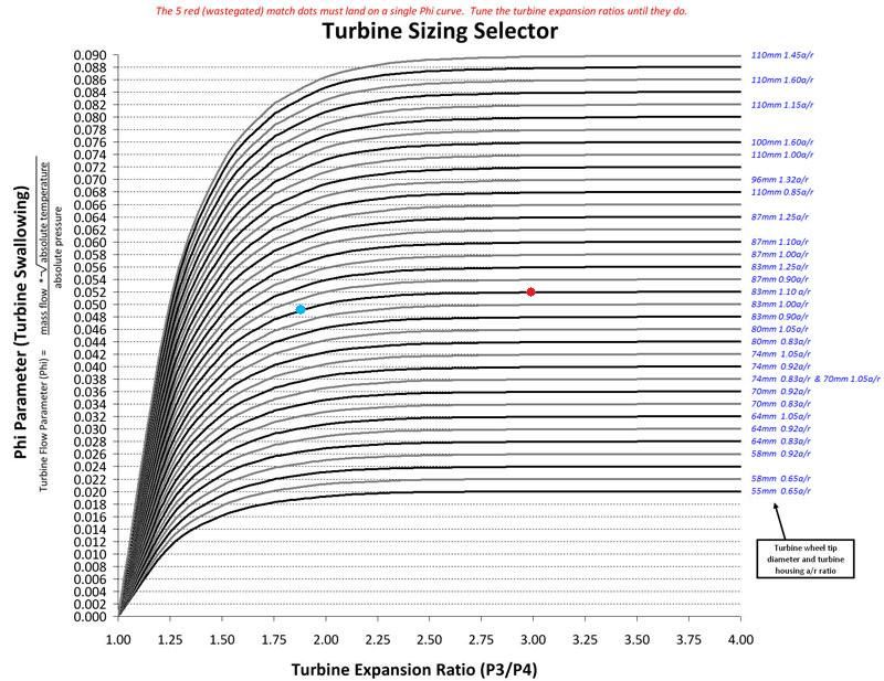
I believe it will not work as shown in the diagram because the turbo has no waste gate. In fact it has a negative waste gate. It gets spooled up by battery power which you cannot show in a conventional turbo diagram. As rpm and mass flow builds the spool up power from the MGU is reduced to zero. Somewhere between 0-20 hp compressor power and 62 hp turbine power you cross that point. Then the MGU goes continuously into generation mode as turbine power keeps building up to the full 124 hp and compressor power keeps building up to 40hp. It is a continuous steady function of increasing the power of both units. The electricity generation has the function of the waste gate in a conventional turbo. It absorbs the excess power when the turbine has reached the cross over point.pgfpro wrote:IMO when the MGUH goes to full load say 84HP it will move to the right of the turbine map with a increase in pressure.
Example:
Blue dot compressor only with MGUH disable
Red dot compressor and full load 84HP from MGUH
So are you saying when the MGUH goes into generation mode and puts a load on the turbine there won't be an increase in turbine pressure???WhiteBlue wrote:I believe it will not work as shown in the diagram because the turbo has no waste gate. In fact it has a negative waste gate. It gets spooled up by battery power which you cannot show in a conventional turbo diagram. As rpm and mass flow builds the spool up power from the MGU is reduced to zero. Somewhere between 0-20 hp compressor power and 62 hp turbine power you cross that point. Then the MGU goes continuously into generation mode as turbine power keeps building up to the full 124 hp and compressor power keeps building up to 40hp. It is a continuous steady function of increasing the power of both units. The electricity generation has the function of the waste gate in a conventional turbo. It absorbs the excess power when the turbine has reached the cross over point.pgfpro wrote:IMO when the MGUH goes to full load say 84HP it will move to the right of the turbine map with a increase in pressure.
Example:
Blue dot compressor only with MGUH disable
Red dot compressor and full load 84HP from MGUH
I have not talked about the turbine pressure at all. So that is indeed not what I'm saying. Turbine and compressor pressures are dynamic values building continually up as the turbo spools up. There will be no interruption of the pressure build up when the MGU-H controller reaches the cross over point. The pressures will simply keep building up while generator load is build on the turbine.pgfpro wrote:So are you saying when the MGUH goes into generation mode and puts a load on the turbine there won't be an increase in turbine pressure???WhiteBlue wrote:I believe it will not work as shown in the diagram because the turbo has no waste gate. In fact it has a negative waste gate. It gets spooled up by battery power which you cannot show in a conventional turbo diagram. As rpm and mass flow builds the spool up power from the MGU is reduced to zero. Somewhere between 0-20 hp compressor power and 62 hp turbine power you cross that point. Then the MGU goes continuously into generation mode as turbine power keeps building up to the full 124 hp and compressor power keeps building up to 40hp. It is a continuous steady function of increasing the power of both units. The electricity generation has the function of the waste gate in a conventional turbo. It absorbs the excess power when the turbine has reached the cross over point.
In my example the blue dot is after the full spool from the battery power. At this point you have almost reach max flow through the turbine. IMO you have to be at max turbine flow with a radial turbo before you can start adding a generator load to the turbine.