Rotary Hill Climb Drawing

Post here information about your own engineering projects, including but not limited to building your own car or designing a virtual car through CAD.
User avatar
RicerDude
27
Joined: 10 Sep 2012, 20:21

Rotary Hill Climb Drawing

Post

Hello, this is a project I have been working on for the past month.
It's an open wheeled hill climb style car powered by a milled out, turbocharged, 4 rotor 3.0l Mazda R26B.
I got the inspiration to make this design from this guy : http://rotaryhillclimbracing.com
I made the design on Autodesk Inventor software. The car is far from complete but I am running out of RAM to power the file so I decided to post the car here unfinished because it may be some time before I can update it :( .

Here are some renders of the car in its current state...

Image

Image

Image

Image

Image

I will try to go into as much detail as my computer will allow.
Next steps will be to finish off the chassis, detail the cockpit and do the front and rear suspension then I will probably need to get some more RAM.
Any feedback will be appreciated.

User avatar
amouzouris
105
Joined: 14 Feb 2011, 20:21

Re: Rotary Hill Climb Drawing

Post

Replace your hard disk with a solid state drive. That will help massively! They are getting cheaper and cheaper

Edit: as far as the rear wing is concerned, why the use of a low aspect ratio wing?

wesley123
204
Joined: 23 Feb 2008, 17:55

Re: Rotary Hill Climb Drawing

Post

amouzouris wrote:Replace your hard disk with a solid state drive. That will help massively! They are getting cheaper and cheaper

Edit: as far as the rear wing is concerned, why the use of a low aspect ratio wing?
True that will help massively on pace, until you run out of RAM. RAM memory isnt expensive either though.


But OT: Looks cool! has a bit of a 80's feel to it with the Radiators placed that way.

Also, is it me or does the car looks to have a really long wheelbase?
"Bite my shiny metal ass" - Bender

Lycoming
106
Joined: 25 Aug 2011, 22:58

Re: Rotary Hill Climb Drawing

Post

RAM is dirt cheap right now, get it while it's hot. a solid state drive won't help you unless you want to run a huge page file on it, and even then it will be slower than if you just got more ram.

User avatar
RicerDude
27
Joined: 10 Sep 2012, 20:21

Re: Rotary Hill Climb Drawing

Post

The rear wing is mounted about 75cm away from the rear axel so my theory is (correct me if I'm wrong) that the downforce will place more load on the rear wheels because it has more leverage around the front axel but only if I can balance the downforce at the front. Which is why I have gone for a narrower rear wing . I will probably have a two tier front wing similar to the 70's hesketh James hunt drove.

As for the wheel base I think it's a normal size but it just looks long because of the extended rear wing.

User avatar
amouzouris
105
Joined: 14 Feb 2011, 20:21

Re: Rotary Hill Climb Drawing

Post

Actually a solid state and RAM work on the same principle..memory wise...they use NAND gates, whatever the computer cannot store onto the RAM for immediate access it stores it onto the hard disk, It worked wonders with my computer and solidworks! Change both and though cause as others said they are cheap

Edit: Extremely detailed models can get MASSIVE, ones they can no longer fit into RAM they are stored also on the HDD and there you can see the immediate reduction in speed

Lycoming
106
Joined: 25 Aug 2011, 22:58

Re: Rotary Hill Climb Drawing

Post

They're both random access, but they're not really the same; DDR3 is volatile, NAND flash is not. DDR3 doesn't really have a write cycle limit, NAND flash does (an increasingly restrictive one at that). The overflow that cannot be stored on the RAM is stored on hard disks/SSD in a file called the page file. Accessing from the page file is still slower than accessing from RAM, though the difference isn't that big with an SSD. If your model is getting ridiculous in size, I'm sure there's ways to trim it without sacrificing fidelity in the necessary parts. It's a hillclimb car, not a jetliner.

User avatar
RicerDude
27
Joined: 10 Sep 2012, 20:21

Re: Rotary Hill Climb Drawing

Post

As long as I keep the parts small I should be able to complete the model with my existing 4gb RAM but the engine and gearbox part is currently using up maximum RAM because of all the complex lofts for the exhaust and intake manifolds.

spacer
9
Joined: 01 Nov 2009, 20:51

Re: Rotary Hill Climb Drawing

Post

Haven't worked with Inventor in a while, but Solidworks alows you to show certain components within a large assembly to be opened lightweight. It shows your part with decent accuracy (more than enough to design around the part without having to worry about packaging issues), but doesn't load every single small feature and detail. I'm quite sure there's a similar option in Inventor.
No need for the exhaust manifold flanges to be rendered with 0.1mm accuracy if you're working on front suspension.

Try it, it allows me to work in an assembly of an entire car (modelled up to every single bolt) on a fairly budget-type laptop.

User avatar
Tim.Wright
330
Joined: 13 Feb 2009, 06:29

Re: Rotary Hill Climb Drawing

Post

Yea ditto that last point. I've also not used Inventor, but any CAD package worth its salt can open large assemblies in a "graphics only" mode whereby only the final geometry is loaded but not all the lofts, sketches and constraints etc... What you have in that assembly there would be dead simple to open up in Catia with the visualisation mode on.

Also, cut down links as much as possible. That is links, constraints, mates etc etc. All they do is slow down an assembly by using computation time and more often than not they cause rebuild errors when you try to change anything. Interesting fact I found was that when you learn solidwaorks/catia/inventor you are taught how to link everything and parameterise everything but when you go out into the industry you realise nobody use this capability because it slows things down and is massively unstable.
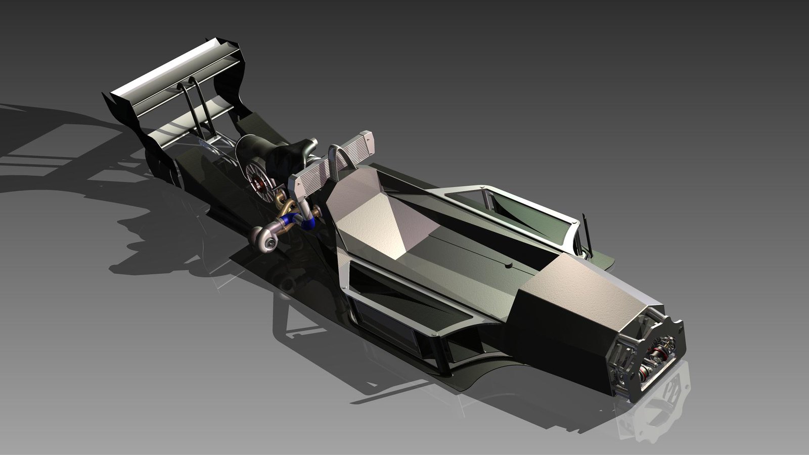
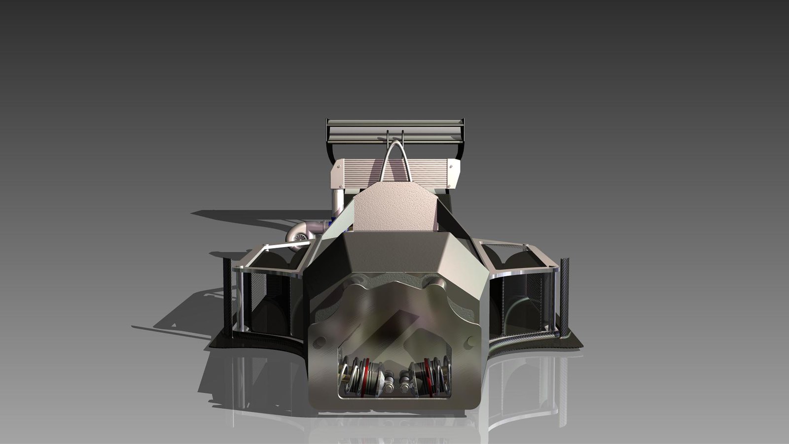
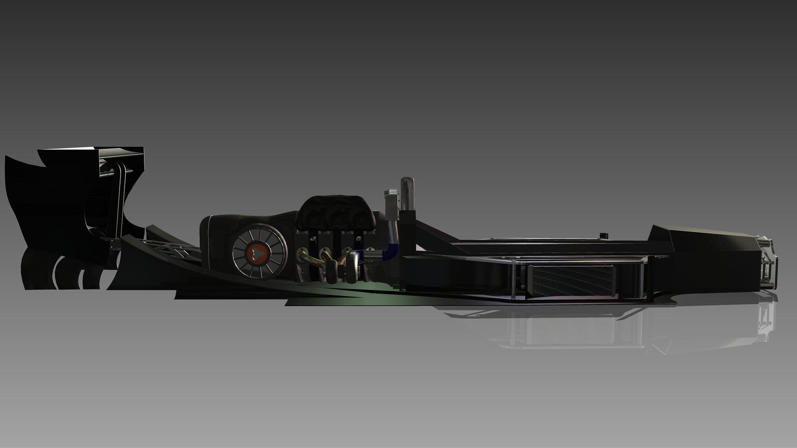
RicerDude wrote:The rear wing is mounted about 75cm away from the rear axel so my theory is (correct me if I'm wrong) that the downforce will place more load on the rear wheels because it has more leverage around the front axel but only if I can balance the downforce at the front. Which is why I have gone for a narrower rear wing . I will probably have a two tier front wing similar to the 70's hesketh James hunt drove.
I've always scratched my head at this "leverage" wing theory. A wing behind the rear axle will produce downforce on the rear axle and lift on the front axle. The further back you move it, the more you lift the front. If you then go and "balance that" by adding a big front wing, the front wing will do the opposite. It will put downforce on the front and lift the rear, putting you back at square 1. Why not just use correctly sized wings in the normal positions to start with?

Then again, do you even know where you want your centre of pressure to be?
Not the engineer at Force India

User avatar
andylaurence
123
Joined: 19 Jul 2011, 15:35
Contact:

Re: Rotary Hill Climb Drawing

Post

That's a nice looking render. What's the reasoning for starting the tunnels so far back? There's scope to move them forwards, which means you don't need to run such a big front wing to balance out the rear wing. The tub looks very low - almost like the driver would be lying down - but that could just be perspective. The cross-section of the tub also looks large, but that could just be the shape of it at the front. The CoG looks like it'll be quite low with the low nose and what looks like a pull-rod front. Is that a carbon tub?

MadMatt
125
Joined: 08 Jan 2011, 16:04
Contact:

Re: Rotary Hill Climb Drawing

Post

It looks really good! I am just worried about the intercooler's position, that will massively increase the drag and upset the airflow to your rear wing. I hope you can find some better computer to continue your project! What RAM size are we talking about there?

User avatar
RicerDude
27
Joined: 10 Sep 2012, 20:21

Re: Rotary Hill Climb Drawing

Post

Changes I will be making based on your feedback:
Widen the rear wing and bring it further forward (just behind the gearbox).
Bring the entrance of the diffuser further forward.

I also want to know if I exit the exhaust in one side of the diffuser will that give more downforce on one side of the diffuser than the other?
Is that a carbon tub?
It's an aluminium tub. I tried to make a curvy carbon tub but it was very difficult to model using the inventor software and it would have taken up far too much space because of all the lofts.

I will take some arthographic screen shots when I get home to show you the dimensions of the tub and how the person will sit in it.

Smokes
4
Joined: 30 Mar 2010, 17:47

Re: Rotary Hill Climb Drawing

Post

Which version of inventor are you using 2014 should be able to light weight the parts. i would probably use Solidedge or solidworks as inventor is a terrible at handling large assemblys at the moment.

User avatar
RicerDude
27
Joined: 10 Sep 2012, 20:21

Re: Rotary Hill Climb Drawing

Post

Student version of Inventor 2013.