RicerDude wrote:MadMatt wrote:What RAM size are we talking about there
I am currently running with just 4GB RAM (3 useable I think). 8GB will probably be enough but then I will need to buy a 64bit operating system which my computer can run.
Yea with 32bits you are not using the 4GB, I recon that with 4GB you should be able to do everything, I mean I made a whole car (or so) in CATIA with 4GB and it was more than fine. Was lagging a bit when moving the view around the whole assembly but other than that it was fine.
RicerDude wrote:MadMatt wrote:I am just worried about the intercooler's position
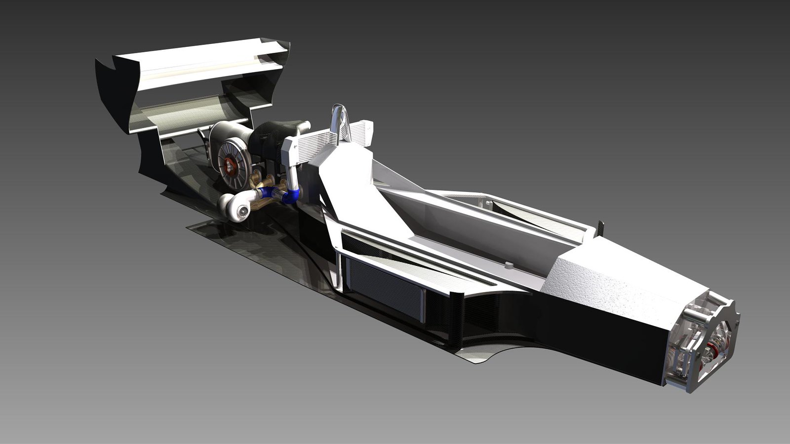
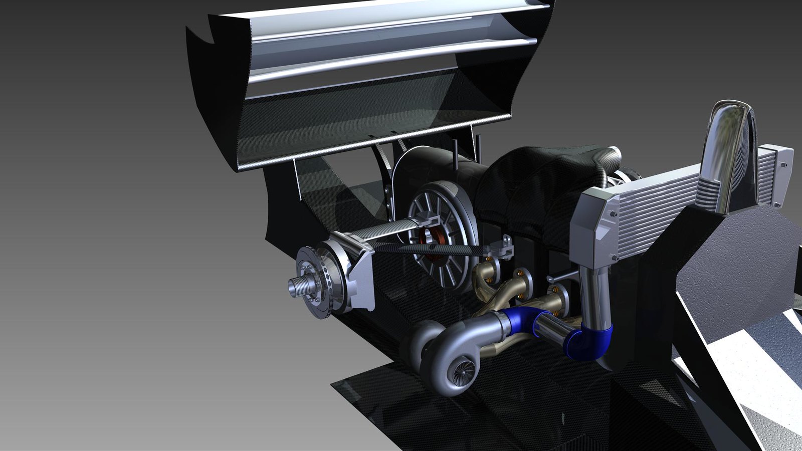
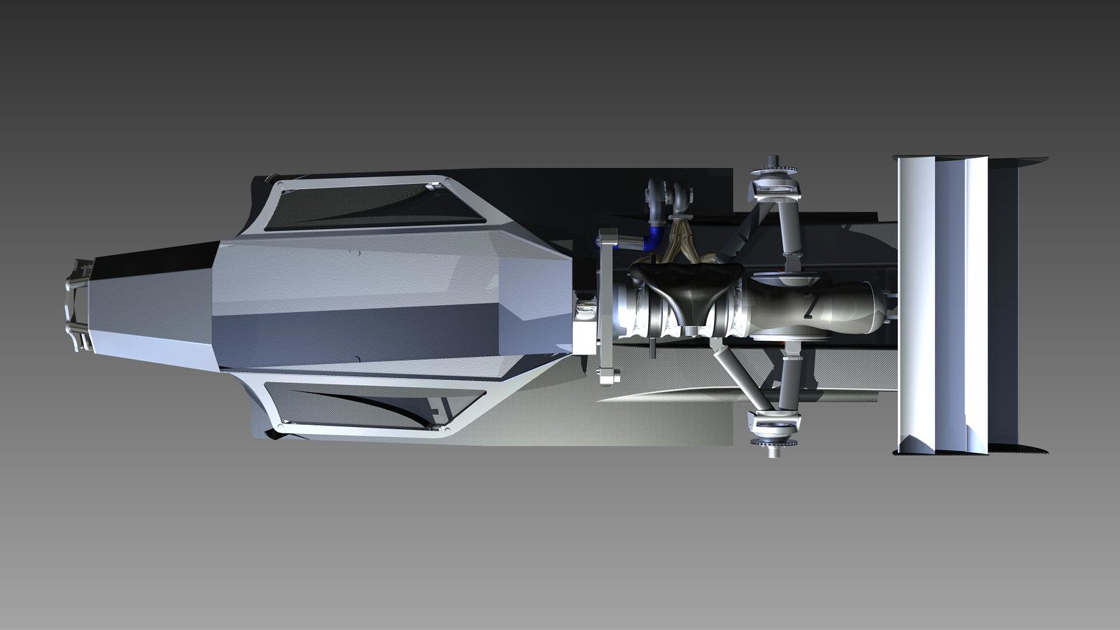
I decided to place the intercooler above the driver because it minimises the length of the turbo tubing which reduces turbo-lag. So I chose to give up a bit of top speed (which isn't really a problem in hill climb) for better acceleration.
Yes minimizing turbo lag by having short hoses is good, on the other hand you can use other methods to avoid too much lag (antilag system, keeping throttle while braking), but from peps that have worked on Cosworth turbo engines, the lag with a big or small intercooler is not really noticeable.
And good luck with the corners, for me it is the most difficult part of the modelling, but your project looks really neat, hope you can solve your computer issues!