A paperboard Lotus E21

Post here information about your own engineering projects, including but not limited to building your own car or designing a virtual car through CAD.
User avatar
PaulB
72
Joined: 17 Oct 2010, 09:52
Location: Graz/Austria
Contact:

A paperboard Lotus E21

Post

Basic Monocoque Drawings

Last night I started with the first basic drawings for the monocoque of my new project, the Lotus E21 of Kimi Räikkönen - btw. my absolute favourite driver. :)

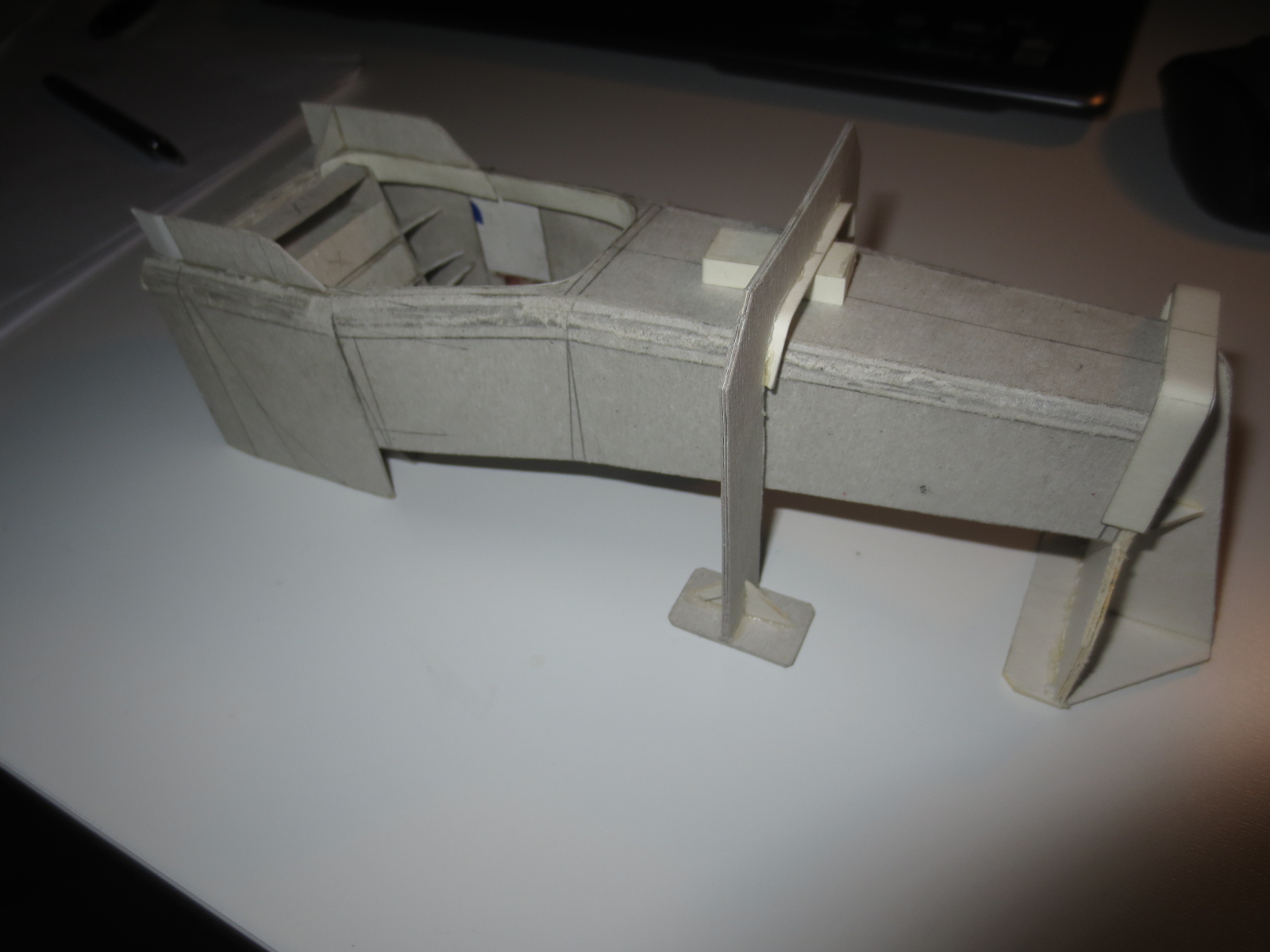
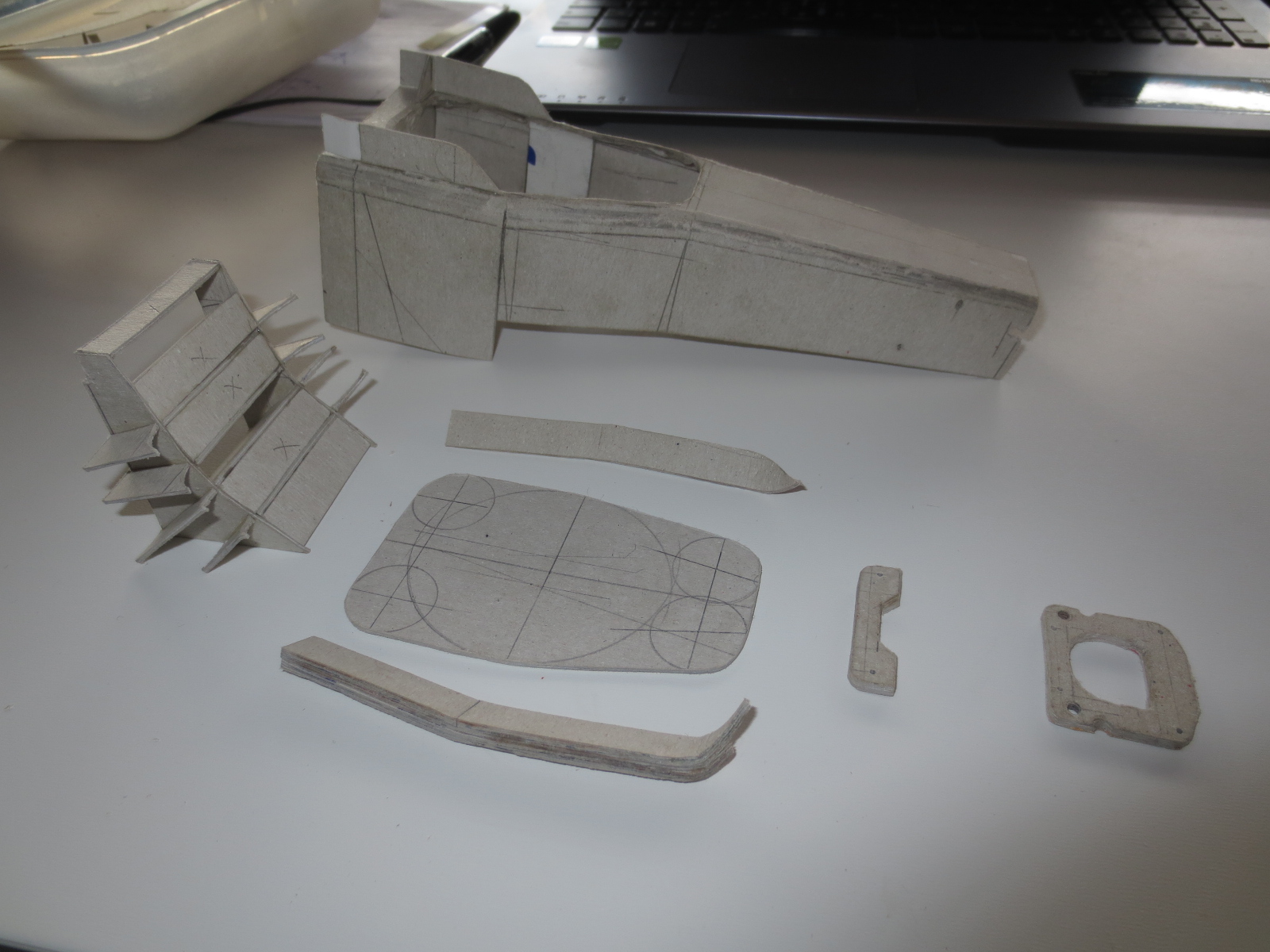
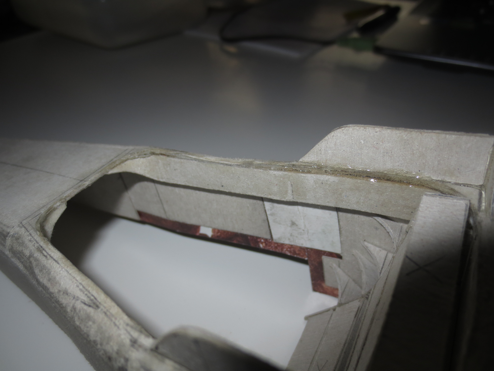
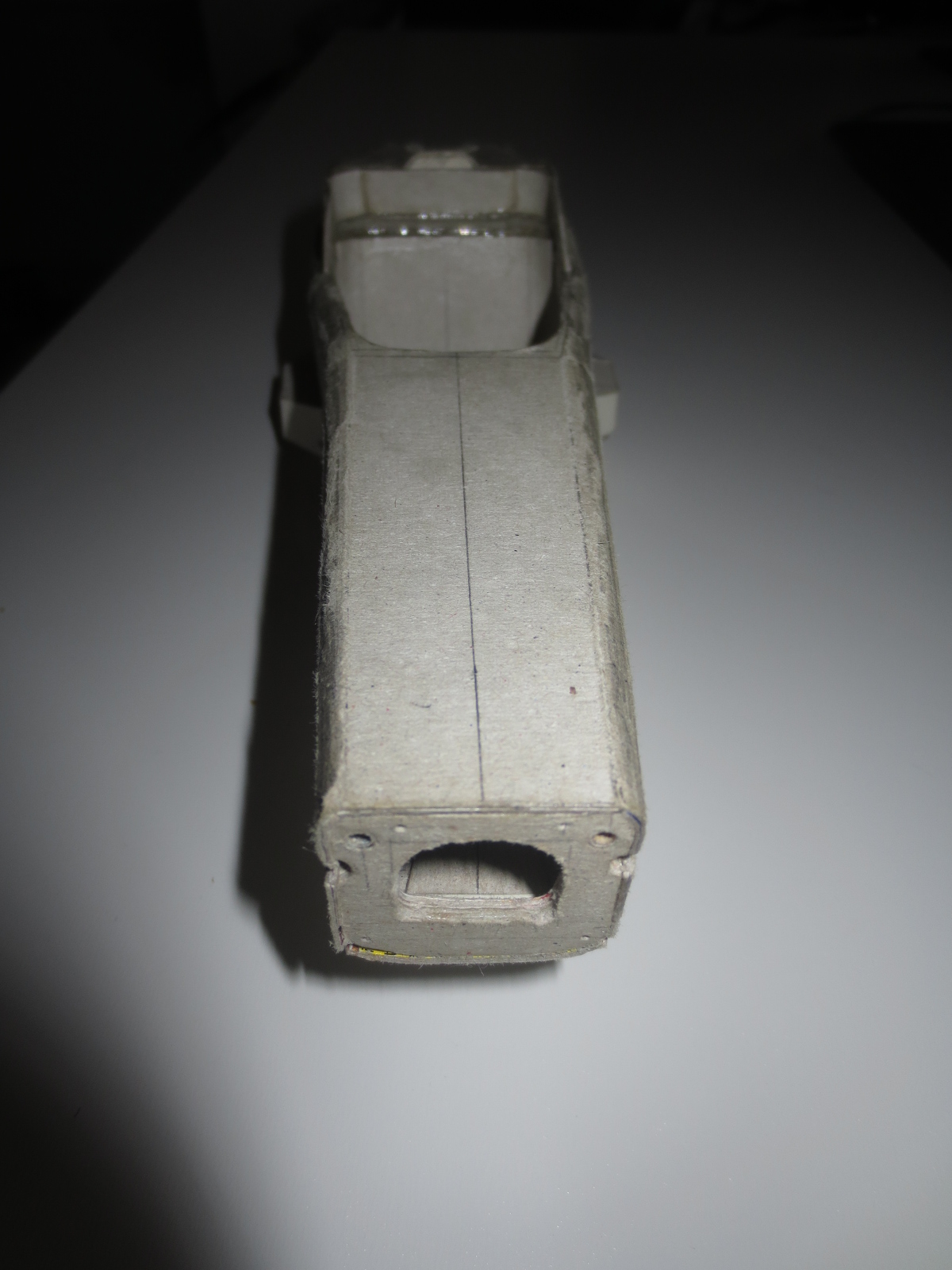
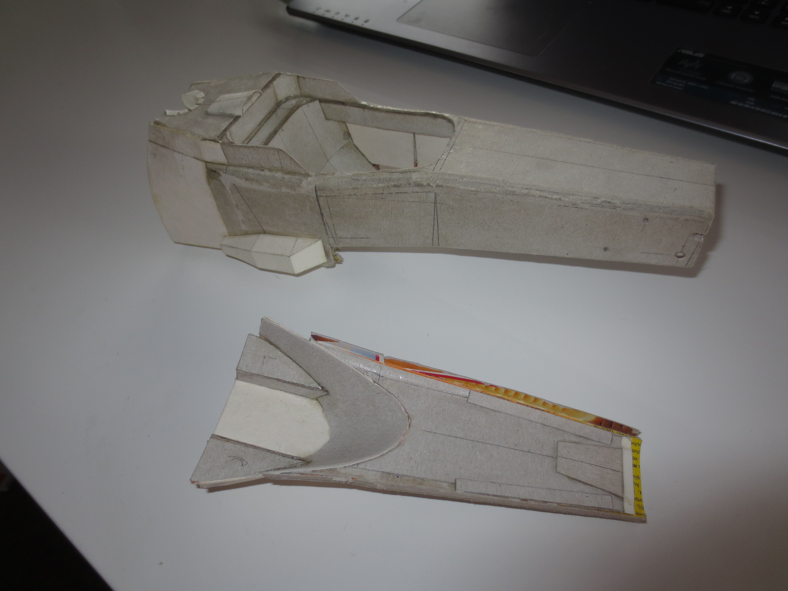
A bit work is left at the rear of the monocoque and at the side pods. At the rear I couldn't reconstruct the correct shape of the cutouts for the cooling lines (water and oil radiator). I hope a few new pics will appear at the GP of Belgium in two weeks where I can spy out the correct shape of this cutout. I've already tried to reconstruct the shape of this cutouts at the predecessors E20 and R30 but didn't find anything helpfull. The correct side pod shape I'll recalculate when I'm starting with the manufacturing of idems.

The engine drawings I can take over from the RB7. It's Renault RS27-2011 is quite the same as the E21's RS27-2013. I've to look if I can find some visible changes between this two versions.

Since the start of the season I've collected 397Mb data from this car. About 1012 pics, tech. regs with appendix, some publications, tech. analysis and so on. A few additional data I collected from the predecesser E20 in case of the engine/engine mounting. a short comparison to my last F1 built, the Red Bull RB7: There I had 277Mb data et the end of the building process. So we can await a much more detailed model of the Lotus than it was at the RB.

Image
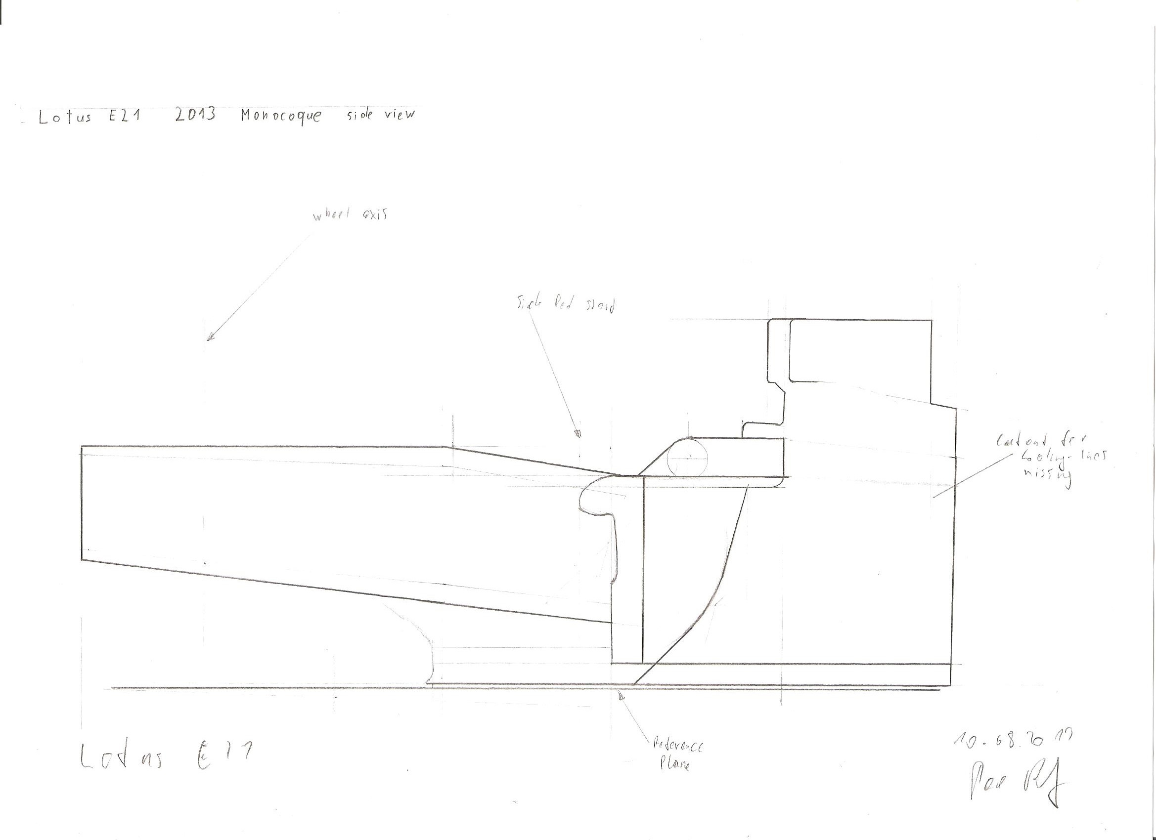
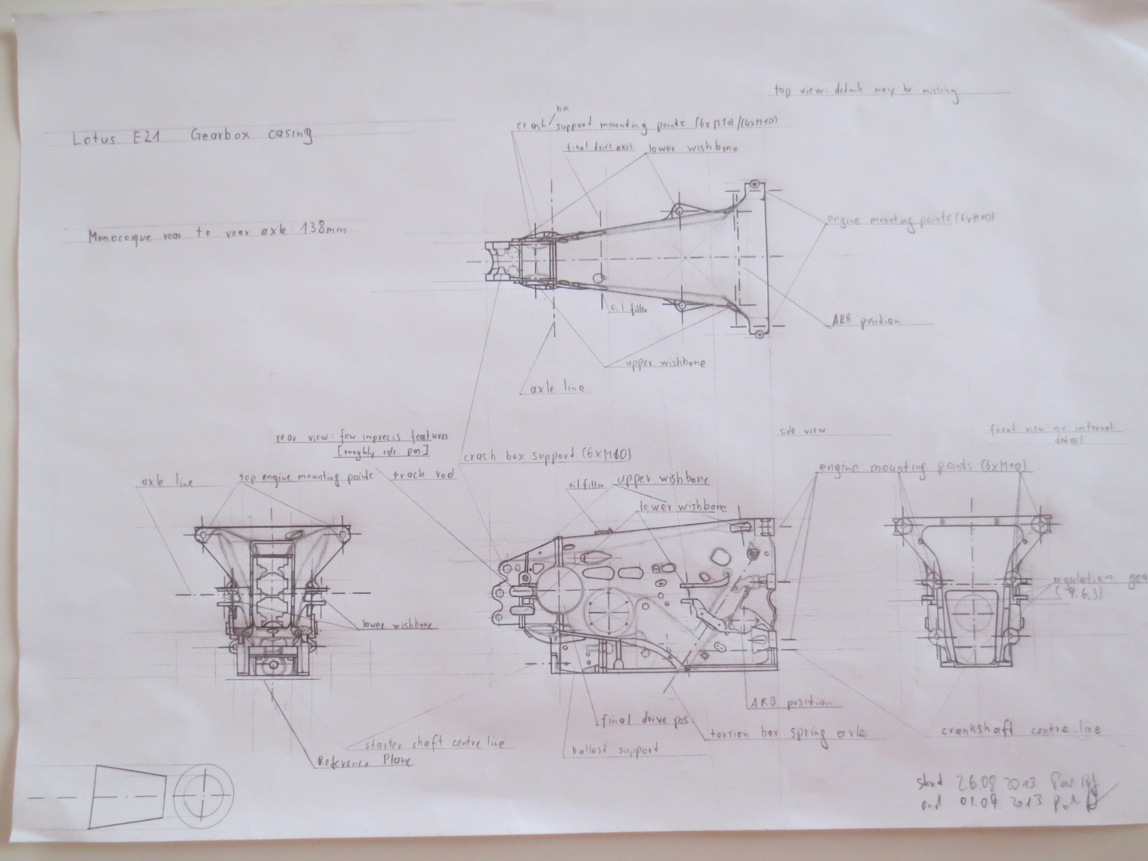
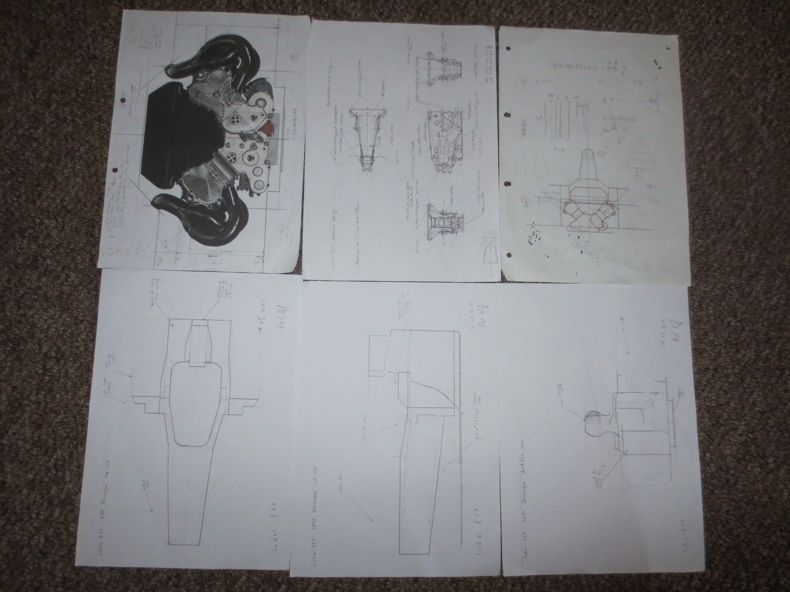
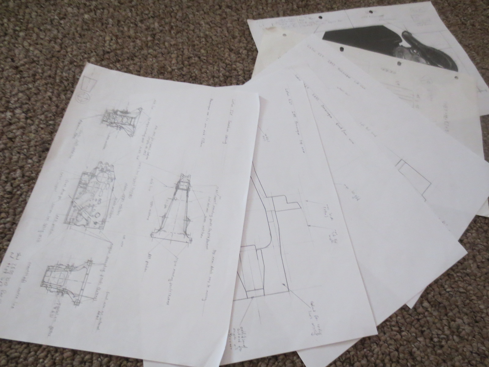
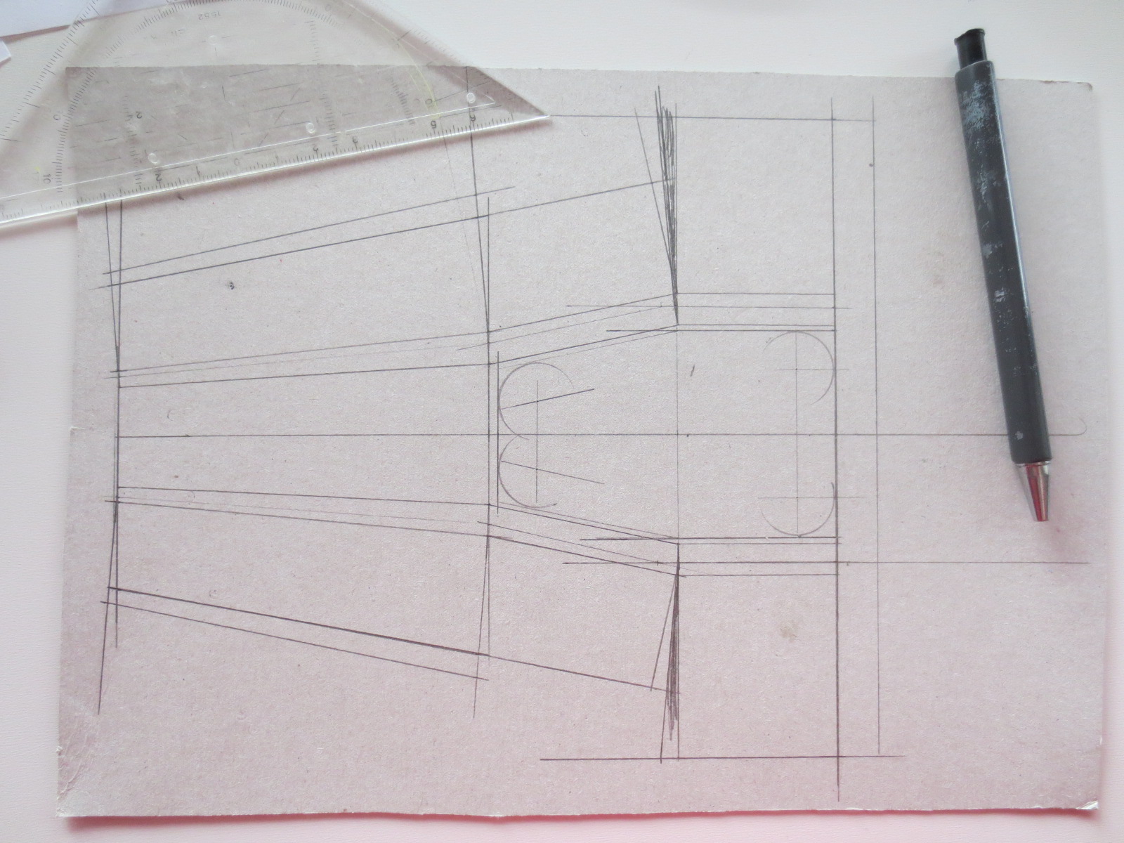
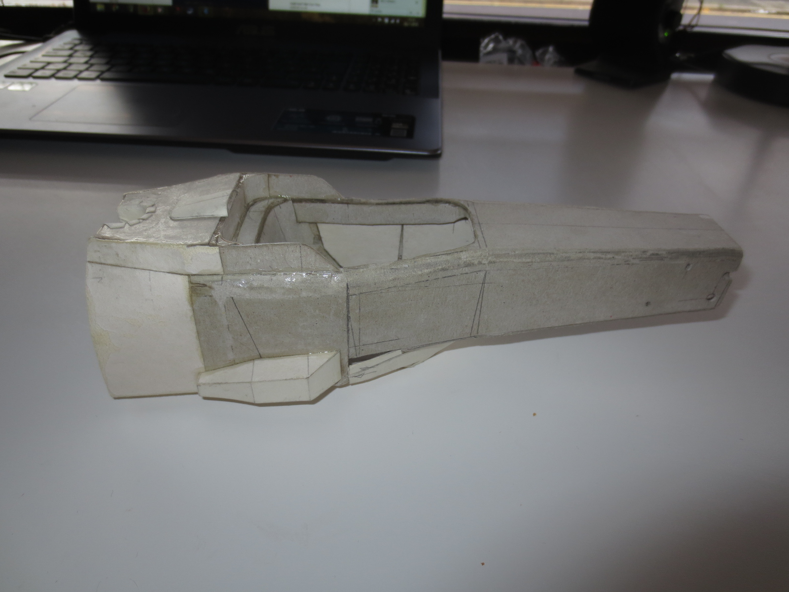
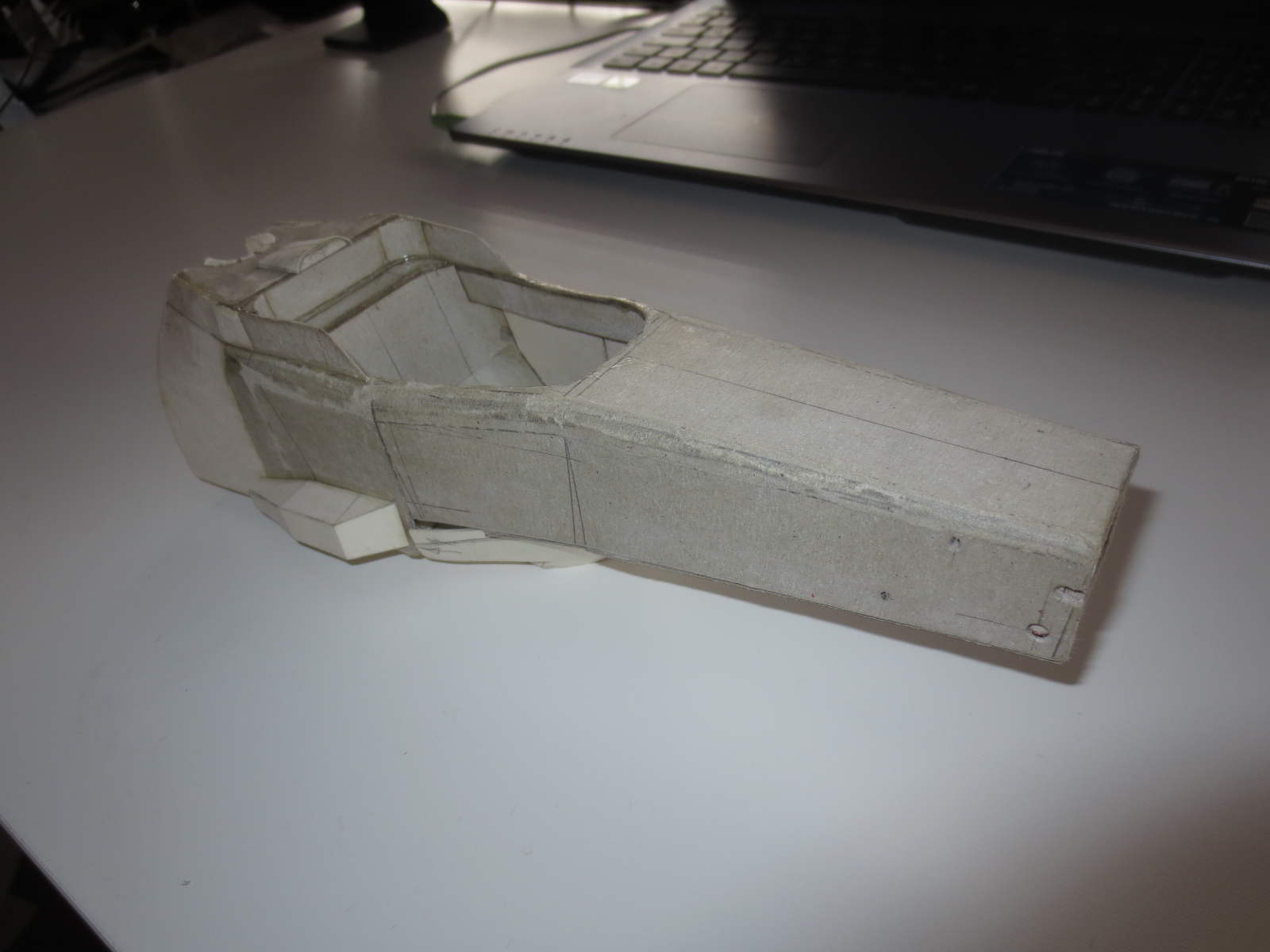
Lotus E21 Monocoque - side view drawing

Image
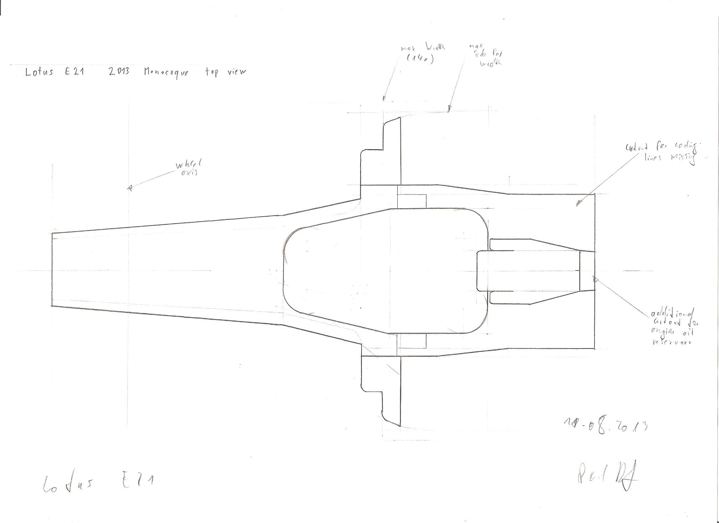
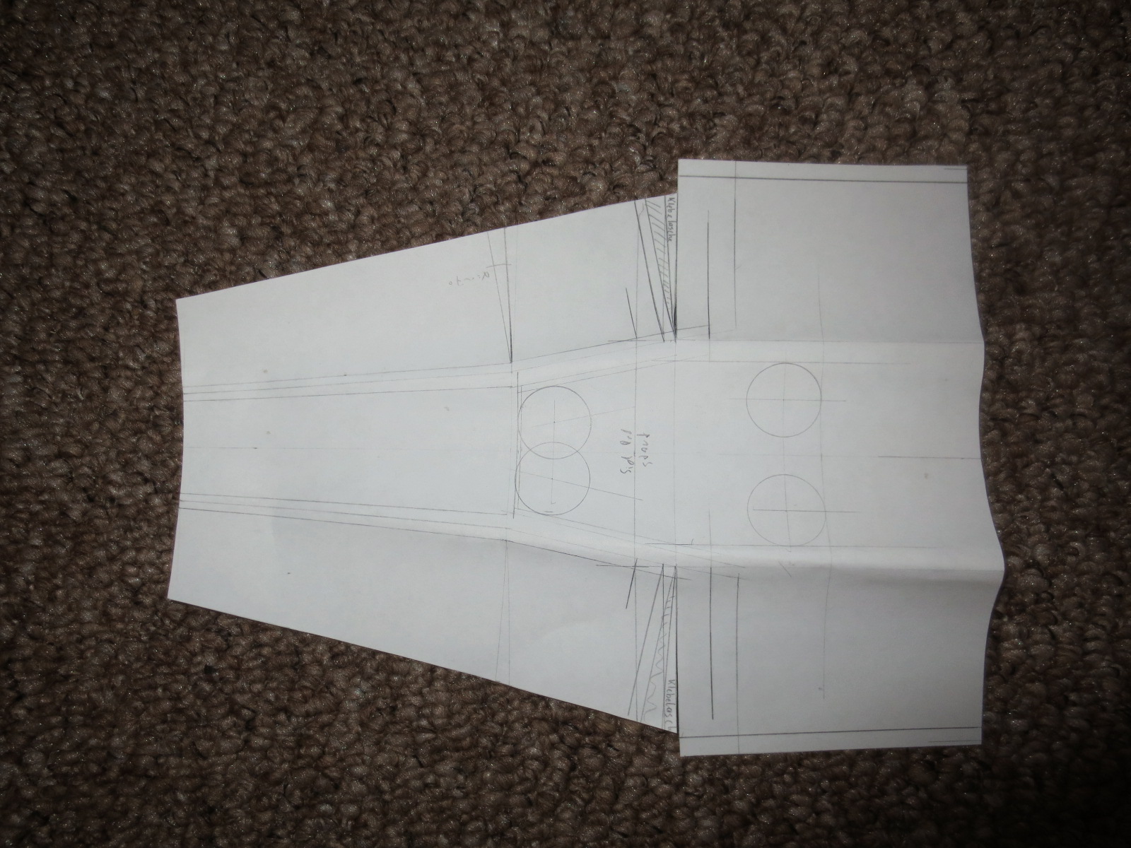
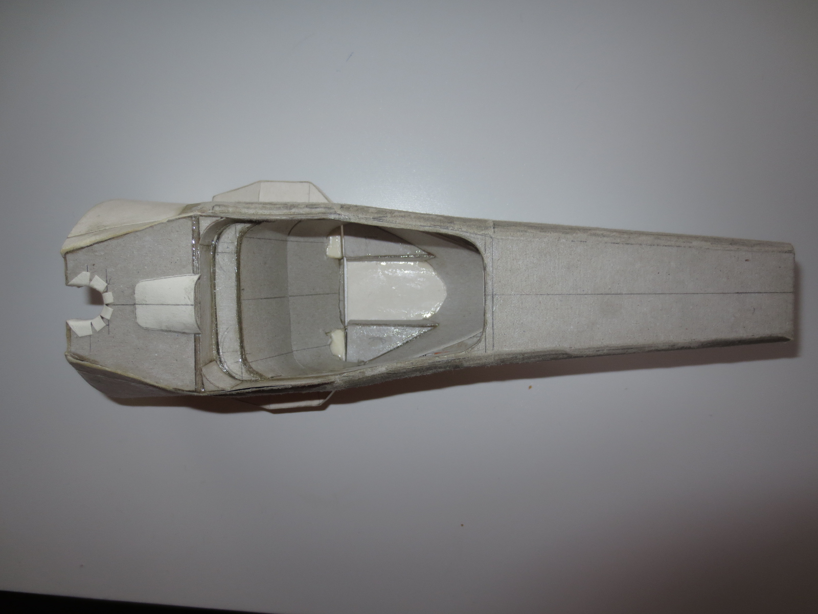
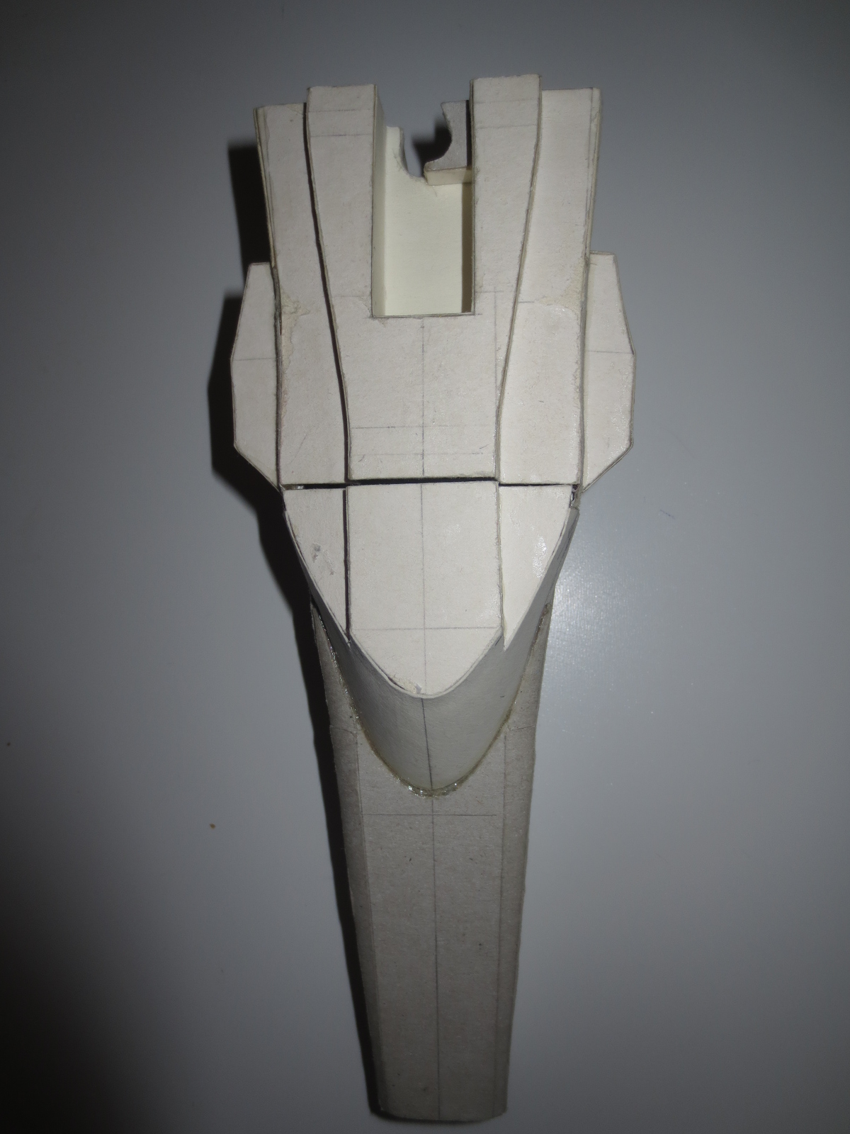
Lotus E21 Monocoque - top view drawing

Image
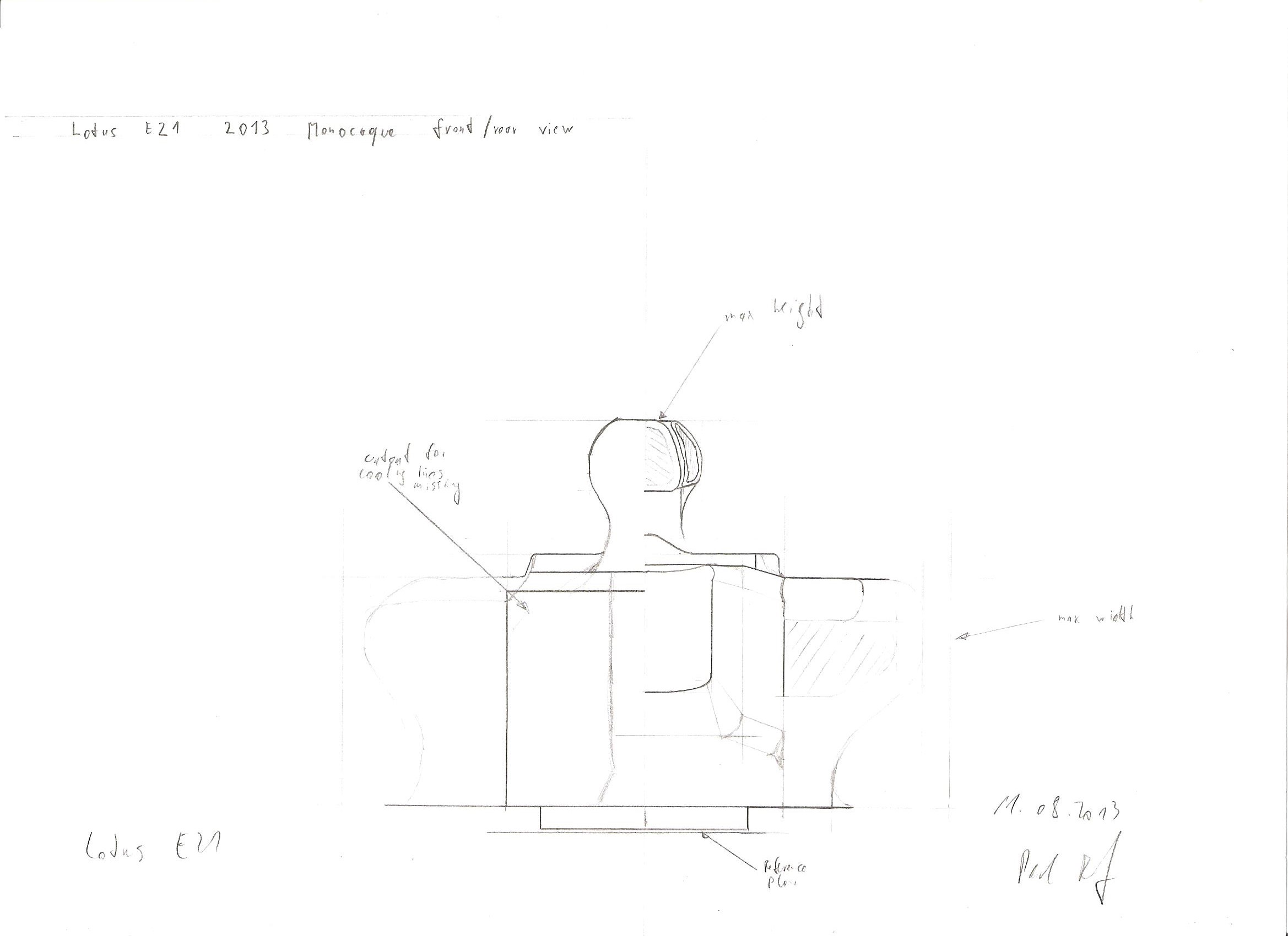
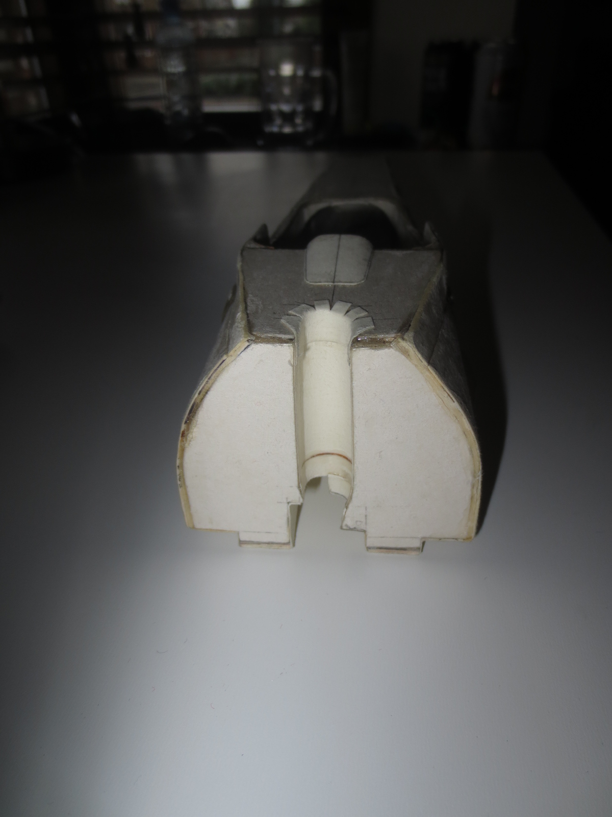
Lotus E21 Monocoque - front/rear view drawing

That's it of the mo, thx for watching.

Cheers,
Paul
Last edited by PaulB on 11 Aug 2013, 18:57, edited 1 time in total.
"Being second is to be the first of the ones who lose!" - Ayrton Senna

Paul Bischof
Milton Keynes, UK
MK2 2HL
http://paulsf1.wordpress.com/

User avatar
hollus
Moderator
Joined: 29 Mar 2009, 01:21
Location: Copenhagen, Denmark

Re: A paperboard Lotus E21

Post

Let me be the first to congratulate you in advance! Looking forward to all the incredible details.
This being you... I assume that the car will be built with "the device" as a dismountable option. But AFAIK we don't really know yet which pipes go where in that case... or maybe you have figured it out?

Edit: Whoever upvoted this, please, take the vote away and take a virtual spanking from me. What in that friendly greeting deserves to be highlighted as useful? The voting system is kind of useful is it is now (IMHO), if we start upvoting each other because we agree on opinions or because something is cool or funny, we'll descend into other-type-of-sites noise very quickly.

Edit-edit: Thanks.
Last edited by hollus on 12 Aug 2013, 17:30, edited 2 times in total.
Rivals, not enemies.

User avatar
N12ck
11
Joined: 19 Dec 2010, 19:10

Re: A paperboard Lotus E21

Post

maybe even make the ears cover-able and uncover-able!
Budding F1 Engineer

CottrellGP
4
Joined: 02 Sep 2011, 01:48

Re: A paperboard Lotus E21

Post

Hi Paul, i cannot wait to see the finished model, i love looking through your work keep up the fantastic work!!
Dan Cottrell

Master Of Innovation!

ajdavison2
30
Joined: 08 Dec 2010, 12:41

Re: A paperboard Lotus E21

Post

love following these posts! Can't wait.

bar555
10
Joined: 08 Aug 2007, 18:13
Location: Greece - Athens
Contact:

Re: A paperboard Lotus E21

Post

drop me a notice in case you need extra images.Great effort BTW
Future is like walking into past......

Blog : http://formula1techandart.wordpress.com/
Twitter :http://twitter.com/bar555onF1

User avatar
Alonso Fan
10
Joined: 06 Apr 2013, 18:21

Re: A paperboard Lotus E21

Post

Fantastic!!

I'm looking forward to see your amazing work progress!

:D
SHR Modding
Youtube
Twitter
Discord

Sound Developer for Reiza Studios
Sound Modder for Assetto Corsa

User avatar
PaulB
72
Joined: 17 Oct 2010, 09:52
Location: Graz/Austria
Contact:

Re: A paperboard Lotus E21

Post

Hey folks!
hollus wrote:[...] But AFAIK we don't really know yet which pipes go where in that case... or maybe you have figured it out?
Already figured it out.

With the completion of the gearbox drawings for the Lotus E21 I'm now ready to start with the manufacturing of my project. The snag on the thing is, that I haven't found a store in Milton Keynes that features my glue (UHU hart). At least I managed to find a store that features my working material such like card, gold foil (for heat shields) and stuff like that.

Anyway, everything is completed for starting with the monocoques manufacturing. I've already done the first scheme for the monocoques basic structure ply. I've even eaten two packs of cornflakes that I have enough cardboard for the basic structure of the monocque. :)

Gearbox drawing of the Lotus E21 Titanium gearbox.
Image

As you can see, meanwhile I've enough stuff to start with the manufacuring of the car.
Image

The engine drawings I took over from the RB7.
Image

The first attempt scheme for the basic structure of the monocoque.
Image

Basic material for the monocoque structure is also ready. :)
Image

That's it for the mo, thx for watching.

Cheers,
Paul
"Being second is to be the first of the ones who lose!" - Ayrton Senna

Paul Bischof
Milton Keynes, UK
MK2 2HL
http://paulsf1.wordpress.com/

User avatar
Paul
11
Joined: 25 Feb 2009, 19:33

Re: A paperboard Lotus E21

Post

Nestle should consider sponsoring you! :D

Stackhouse
0
Joined: 13 Sep 2013, 19:32

Re: A paperboard Lotus E21

Post

Can't wait to see this finished

marcush.
159
Joined: 09 Mar 2004, 16:55

Re: A paperboard Lotus E21

Post

paul ,
as much as I admire your papermodeling ...but are you sure one should eat those loops? I would certainly go ballistic if my kids would ask to buy a package of those..... :mrgreen:

User avatar
PaulB
72
Joined: 17 Oct 2010, 09:52
Location: Graz/Austria
Contact:

Re: A paperboard Lotus E21

Post

Hey guys,

as you may have recognized, there wasn't a lot of action on my models the last days. Reason for that was, that my laptop was down and I had no material to work. Now these problems are conquered.
Paul wrote:Nestle should consider sponsoring you! :D
Maybe I should email them. ;)
marcush. wrote:paul ,
as much as I admire your papermodeling ...but are you sure one should eat those loops? I would certainly go ballistic if my kids would ask to buy a package of those..... :mrgreen:
Why not? They taste quite good. But after a few weeks you don't like them anymore, so I switched to cereal cockies a few week ago. :D

The basic upper shape of the monocoque is finished, now I just have to add a few inserts such as for wishbone or damper mounting points. I am thinking about doing a real inspection door as it is like at the real car at the top of the monocoque to reveal all the inside front suspension stuff as well as the pedals. Next steps will be to design the lower half of the monocoque with the keel and the cockpit floor as well as the fuel cell housing.

As usual I use the technical reguilation stuff for dimensioning the chassis:

-2013 FORMULA ONE TECHNICAL REGULATIONS
-Appendix to the 2013 FIA Formula One Technical Regulations

In the course of this building process I will refer again and again to this two documents.

The basic part of the monocoque - the first ever part of every car. If you are a bit creative, you can imagine how I bend this part and identify the monoqoues shape.
Image

Here you can see the basic shape with a few jigs to ensure that the chassis is within the regulations. Ref. 2013 FORMULA 1 TECHNICAL REGULATIONS-Drawing 5
Image

A few items to glue into the monocoque.
Image

Front bulkhead and front rocker bearing carrier. At the front bulkhead you can see the two big holes to adjust the front torsion bar springs. I assume to change the spring rate, they simply change the torsion bar. Also the four pick up points for the nose cone are visible.
Image

The basic shape of the cockpit rear end bulkhead (seperating wall between cockpit and fuel cell). I actually don't know if I just use it as a jig to bond the bulkhead into the chassis or if I use it as an integral structural part in the monocoque (bond it in).
Image

Cockpit entry template structural inserts left and right. The sheet between them is the jig to control the shape of the cockpit entry.
Image

Front bulkhead and rocker bearing carrier bonded in. At the cockpit entry template you can also see the inserts.
Image

Cockpit entry template. The inserts at the side have the function to reinforce this area of the chassis as it is naturally the weakest point at the monocoque as it represents a open profile and as we know, a open profile hasn't got a high torsional section modulus. I also used two different types of cardboard there: The outer shell of this inserts ifs from a card (some biscuits boxes :) ) and the core is a card with a bit a less density just to reach the needed thickness.
Image
"Being second is to be the first of the ones who lose!" - Ayrton Senna

Paul Bischof
Milton Keynes, UK
MK2 2HL
http://paulsf1.wordpress.com/

User avatar
PaulB
72
Joined: 17 Oct 2010, 09:52
Location: Graz/Austria
Contact:

Re: A paperboard Lotus E21

Post

Finishing the structural framework of the chassis

Although I'm working a bit more at the RB10 at the moment, I managed to finish the structural framework of the monocoque/chassis of my Lotus. It's much stiffer than it was at my RB7. Also it's much more detailed and much better designed. When the RB7 monocoque was just the basic shape, I integrated some features like cutout for KERS battery or MGU (Motor Generator Unit). Also the internal structure is figured out much better. I tried to go down with the wall thicknes without loosing any stiffness or run the risk of getting flexible suspension mounting points. So I reinforced the structure just at the areas it's needed. More on this later.

Next thing to do: cover everything with nice carbon coating. :)

Top view: Not much to say about that. At the sides you can see the pontoons where also fuel is stored and electrical stuff is mounted (at the outside).
Image

Rear view: Here you can see the cutout for the engine oil tank. This area will get a bit more detailed when I cover it with the outer surface. At the bottom you can see the cutout for the KERS battery.
Image

Side view: Also not very much to say about this.
Image

Front view: The front bulkhead with its bores for front rockers and the four points for the nose pins.
Image

Bottom view: Here you can see very good the cutout of the KERS batterie. I have almost no information about this bit. I just have a picture of the last years KERS batterie with a mechanic. From this basis I calculated the rough dimensions of the KERS battery. I estimate the size of the battery at about 380x190x155mm (lxwxh). That results in a specific density of about 3.7g/cm³. When you consider the whole clearance and framework within the batterie, that sounds not far-fetched.
Image

Just a view from the rhs front corner.
Image

Of course presently I cannot bond the lower part to the upper one. Otherwise I would not be able to assemble the whole suspension stuff inside.
Image

View inside the monocoque. You can clearly see the whole inserts and reinforcements for suspension stuff and nose accommotadion.
Image

That's it for the mo.

Cheers,

Paul
"Being second is to be the first of the ones who lose!" - Ayrton Senna

Paul Bischof
Milton Keynes, UK
MK2 2HL
http://paulsf1.wordpress.com/

marcush.
159
Joined: 09 Mar 2004, 16:55

Re: A paperboard Lotus E21

Post

=D> =D>
nice display of your craft ...one of the rare highlights in this forum these days...thanks paul

User avatar
PaulB
72
Joined: 17 Oct 2010, 09:52
Location: Graz/Austria
Contact:

Re: A paperboard Lotus E21

Post

Lamination Process has started
marcush. wrote:=D> =D>
nice display of your craft ...one of the rare highlights in this forum these days...thanks paul
Thanks Marcus!

Now it's going to get really interesting. I try as hard as possible, to get the direction and types of the fibres as close as possible to the original. From the inside of the monocoque I have understandably no information about fibre types and directions. But basically in F1 they use three types of fibres: Plain/Basket, Twill and Satin. For Plain and Twill I found some good templates on Google, the Satin I did more or less by myself. Later on I will also have to rescale the textures, because, they use quite big mesh sizes on Plain types especially on the underbody. The direction of the fibres in the cockpit entry area, I can figure out from pictures. Inside the monocoque, I guess they will use mainly quasiisotrop laminate lay-up. So I will mainly use 90° Twill and a bit of Satin on some areas. The side impact Zylon fibres you will not see as they are somewhere under the CFRP fibres.

If somebody does not come to terms with this whole composite stuff, just email me.

Cockpit entry
Image

Chassis front with it's whole suspension stuff.
Image

Thanks for watching,
Cheers,
Paul
"Being second is to be the first of the ones who lose!" - Ayrton Senna

Paul Bischof
Milton Keynes, UK
MK2 2HL
http://paulsf1.wordpress.com/