In this thread I will be unlocking a few secrets hidden within this part. Mainly, its construction, how it was made, and the parts inside and how they go together. I will be cutting sections from it, so anyone who is nervous, or cannot bare to see this sort of stuff cut up then leave now, its not the thread for you. If you have a keen interest then this is the thread for you. You tend to learn nothing by just looking at pretty pictures in terms of Head design so you really have to get inside to unlock all.
To my knowledge, this is the first time this has been done in the public domain.
I do not work directly for any F1 company, and have acquired this head legally.
I have read all disclaimers in reference to second hand F1 parts and what I am undertaking is legal.
I am not going to mention the makers name all the same just Incase Ive missed some small print. If any members want to guess as to which car the head belongs to then guess away, but I will not admit to whether you are right or wrong.
I have chosen to hold back a few pictures of some pneumatic valve train parts since the site owners didn't reply to an email concerning this thread a while back. I asked for a token gift/wall poster given that this thread was a shocking amount of work to get it in a position where the info could be shared and understood easily by all and become a solid reference in time to come for anyone interested. Sadly a response never came.
I have a keen interest as well as experience in Motorsport as well as Aerospace, Metallurgy, and Mechanical Engineering. I have also an extreme Interest in petrol n/a engines, and head design.
I have been researching all this stuff since I was young, and have continued to do so to the current day. I have designed and made many parts mainly from cast aluminium. Doing everything from Design, Costing, Pattern Making, and Machining.
Next year I hope to cast my first 16v cylinder head, doing everything from design, to mould making/pouring/machining etc, myself. I had intended doing it last year but other stuff got in the way.
So thats it, I hope you enjoy and perhaps learn a bit from what I bring to the table. Im doing this analysis for myself, but I feel it would be rude not to share all the same.
The one thing I would ask you to do if you can is to share this info via online media, forums/FB/twitter/Email/Telegraph! etc - it doesn't cost anything to do so but please mention me if you are taking pictures from the thread.
Onto the head then,
It's from a V10 engine making in the region of 850hp with a rpm limit of approx 15,000rpm. It runs pneumatic valve train, has four valves per cylinder, barrel throttles, in-cam oiling, valve axis angled in both planes, bucket tappets, and cam cover coolant distribution. It is also one of the last v10s.
The cam cover(not pictured) is also too a stressed member and it is these that provide location for the top fixing studs to the CF tub.
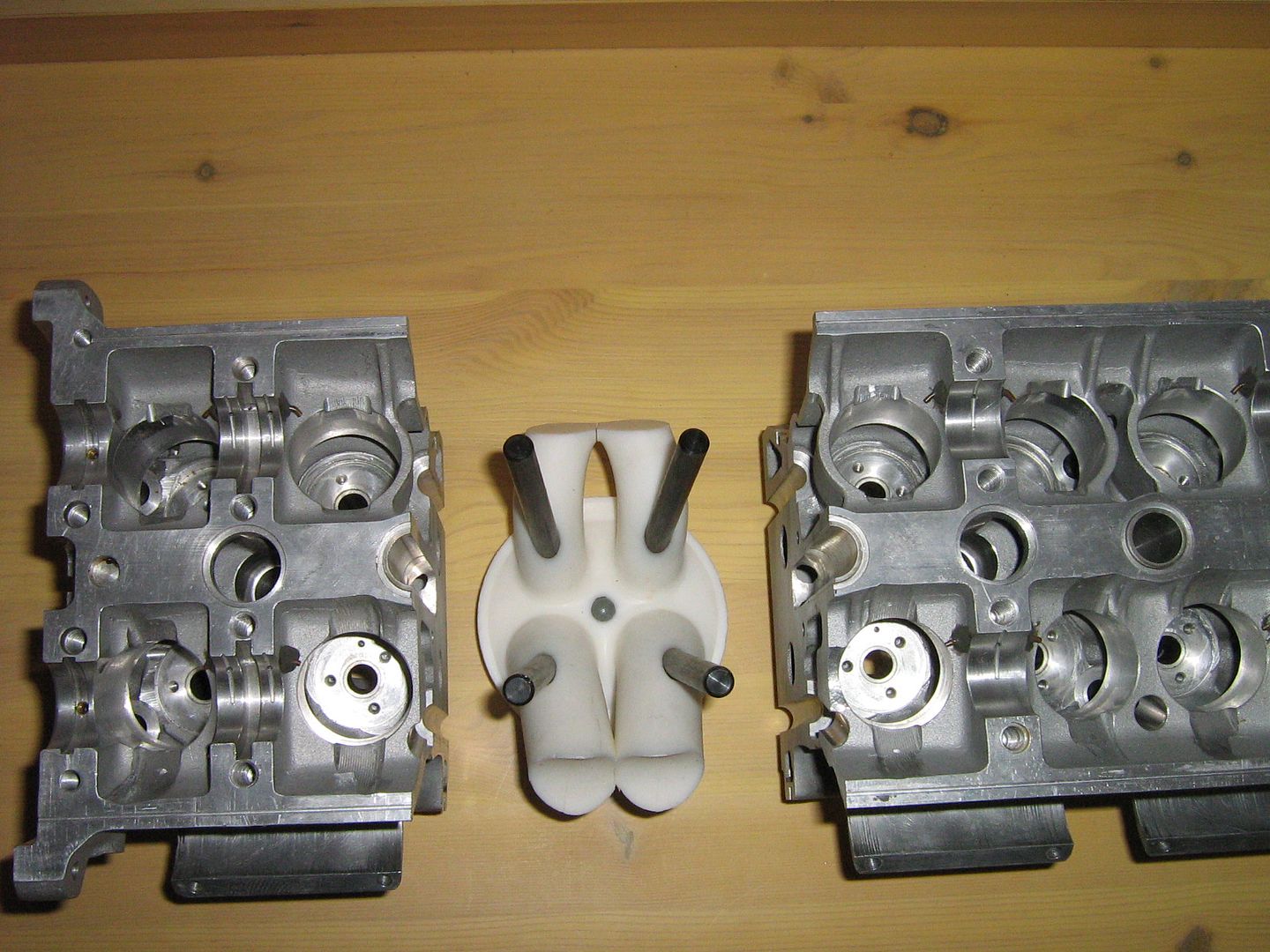
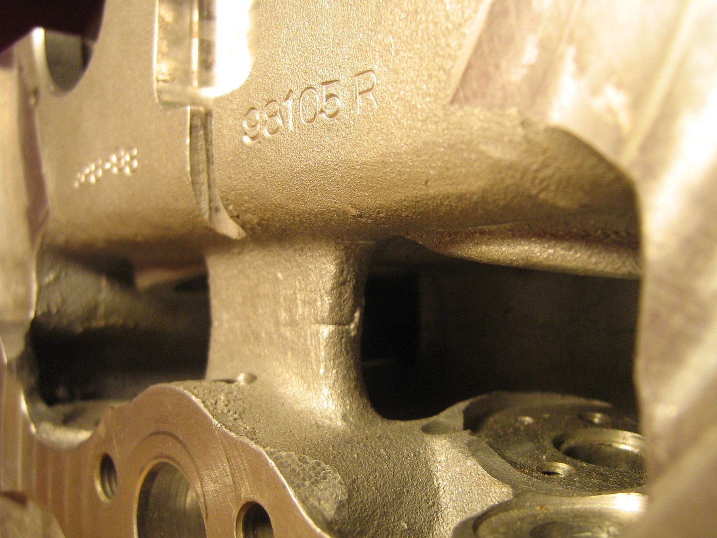
It is important to note that both the right and left bank cylinder heads are identical castings - they are just machined at ends in different ways to make way for the cam gears and so on. This mirroring has many advantages in that it speeds design and production meaning only one head needs to be designed and not two separate head castings. This is something that makes a lot of sense and something that is not immediately apparent after initial analysis.
Internally the head also has the similar design features in that each combustion chamber and the coolant area directly above it as well as the valve actuation are identical on all five combustion chambers along the length of the head.
To put it in other words, the coolant gallery shape, volume, and architecture in general is exactly the same as its adjoining counterparts within the head. This has the benefits of thermal uniformity in respect to coolant, oil, and combustion chamber temperatures along the entire casting.
It also offers the other advantage of the sand cores required to form the coolant gallery above the combustion chamber to be all the same thus requiring just one small core mould to form the entire coolant gallery within the head. Cores are bonded together to a total of five long and installed as a unit within the main sand moulds. It too is a very clever 'modular' system which also saves a lot of design work and indeed coolant flow analysis required in many cases where the coolant gallery is one large free form non-uniform shape within the head. These types of 'non-uniform' galleries are more common in production cars whereby coolant enters or exits the head at one or two points meaning the gallery over one combustion chamber is higher or lower volume to the rest due to the shape required in order to converge coolant towards an opening.
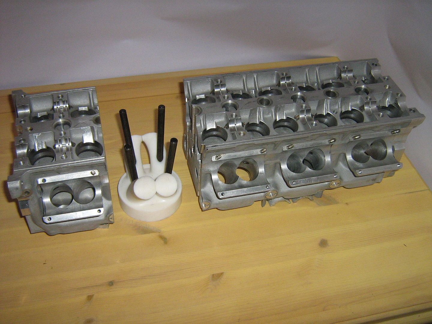
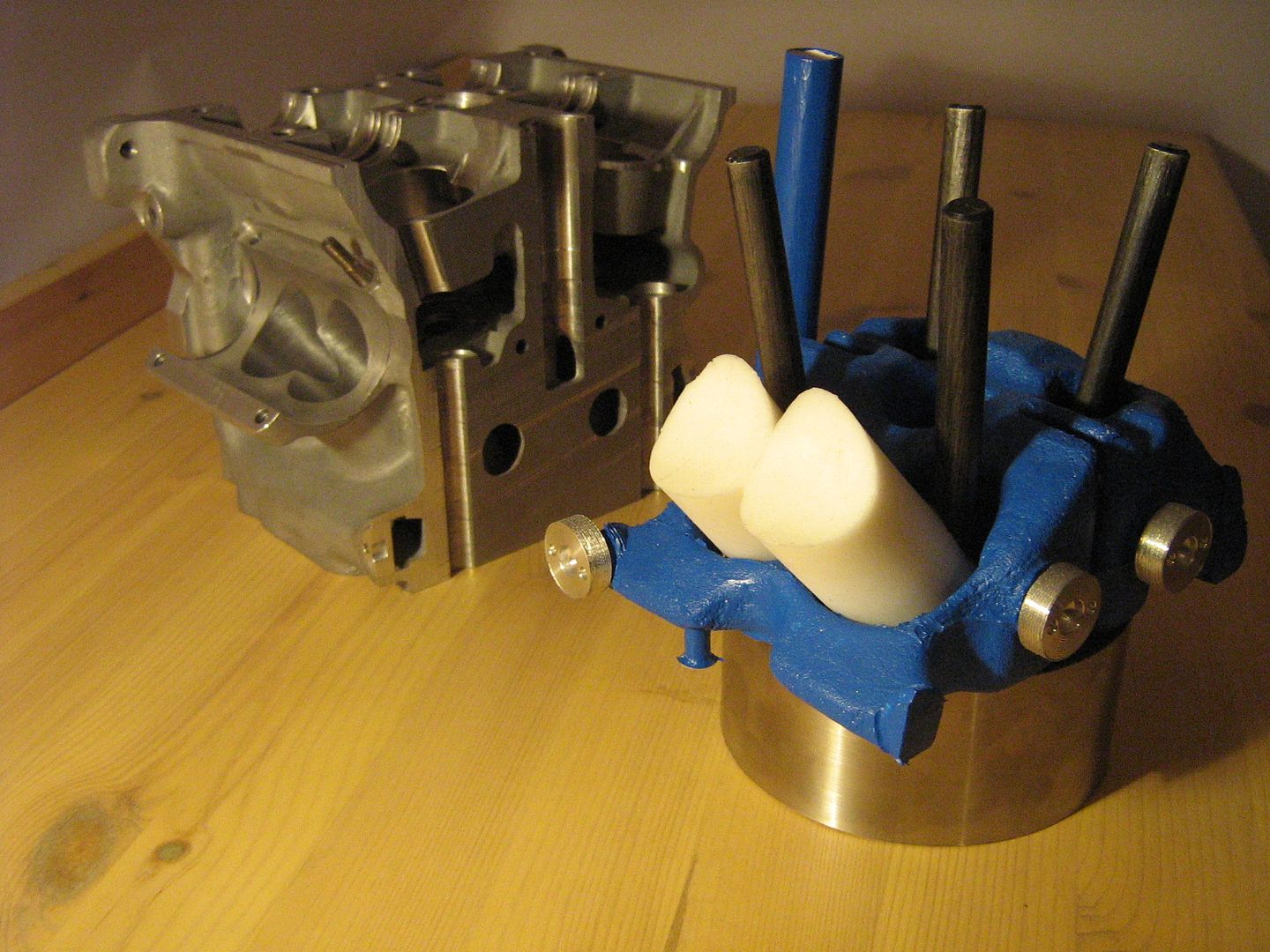
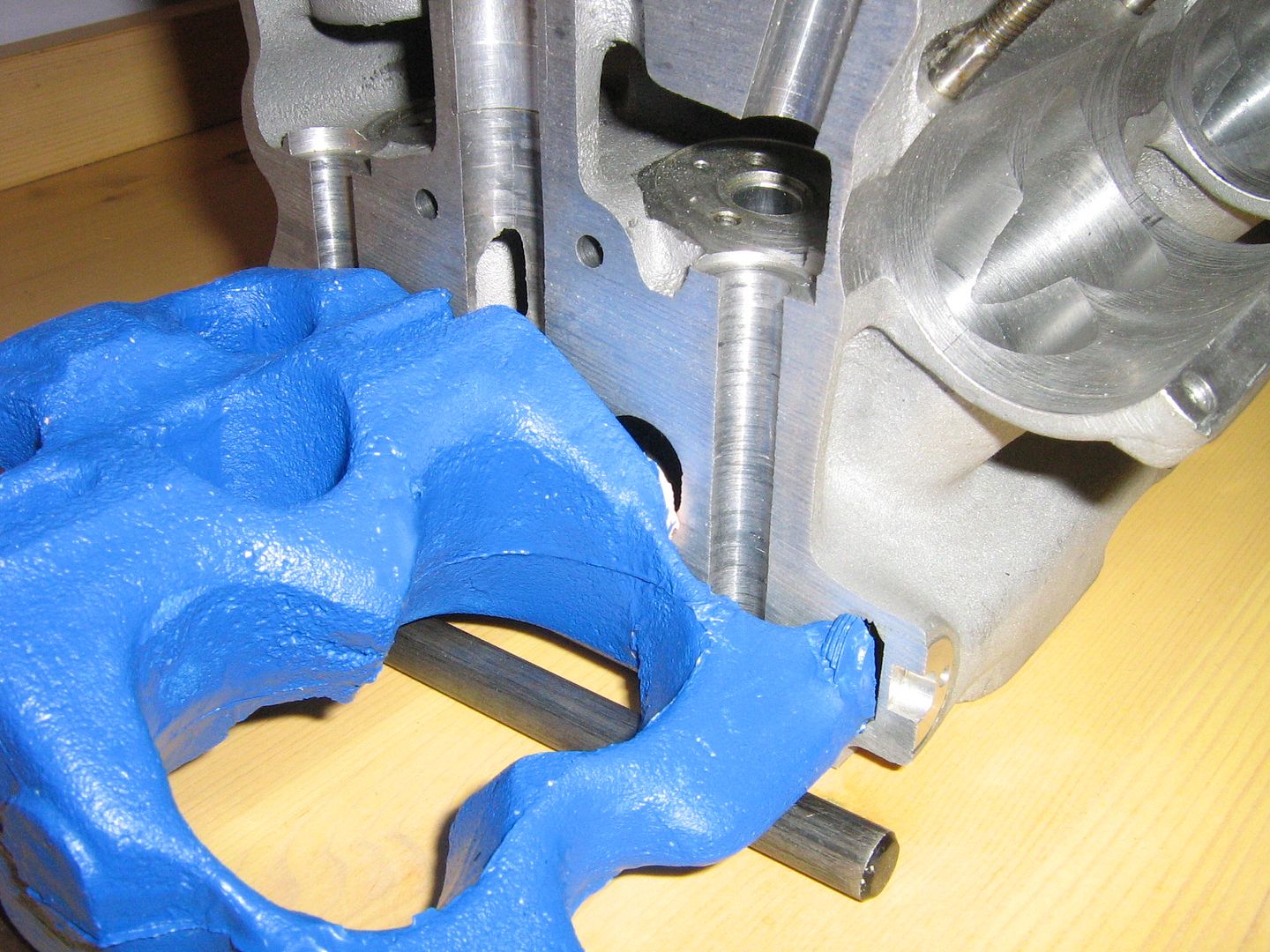
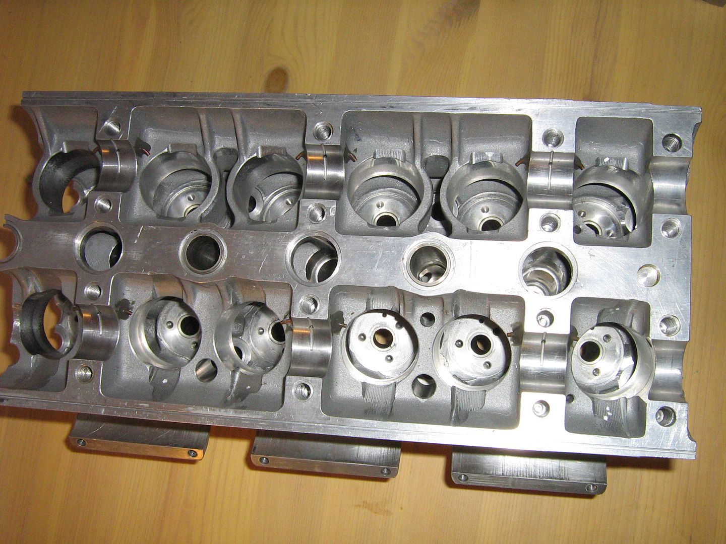
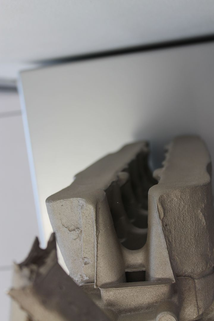
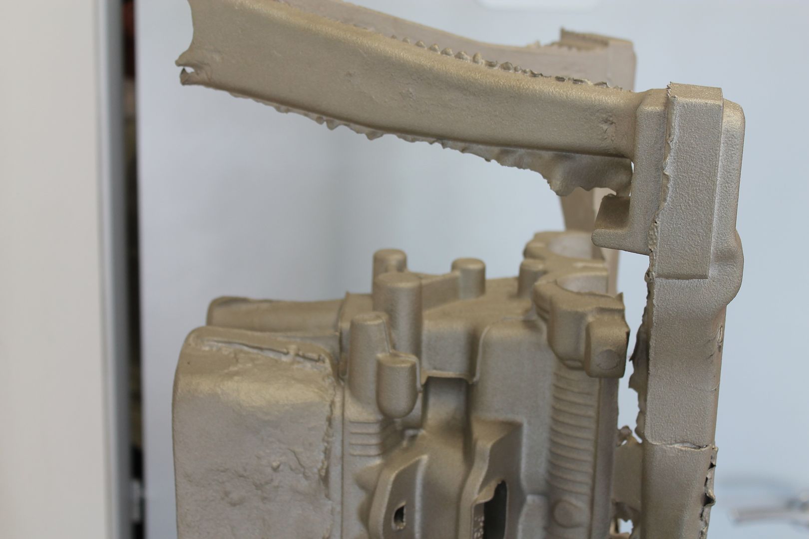
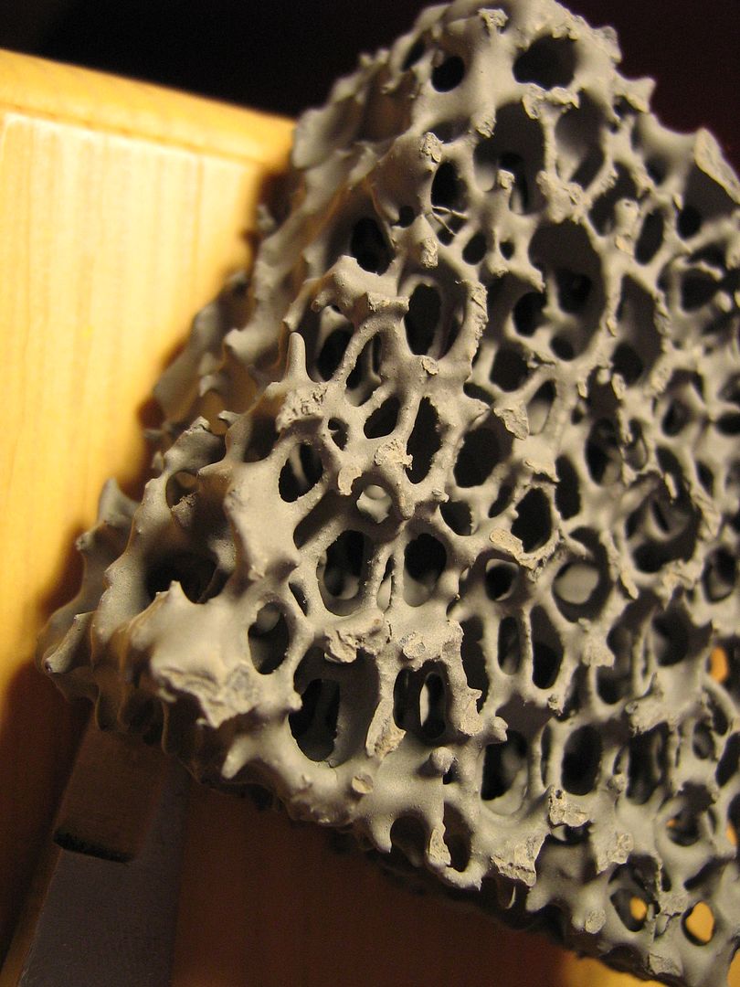
In order to make the internal coolant galleries or 'passageways' easier to understand I have completely removed one cylinder section from the head and sectioned it up. This allows RTV silicone models to be struck off the parts so that a very accurate representation can be made of the internal coolant gallery above the combustion chamber. Since all five are identical only one model is required.
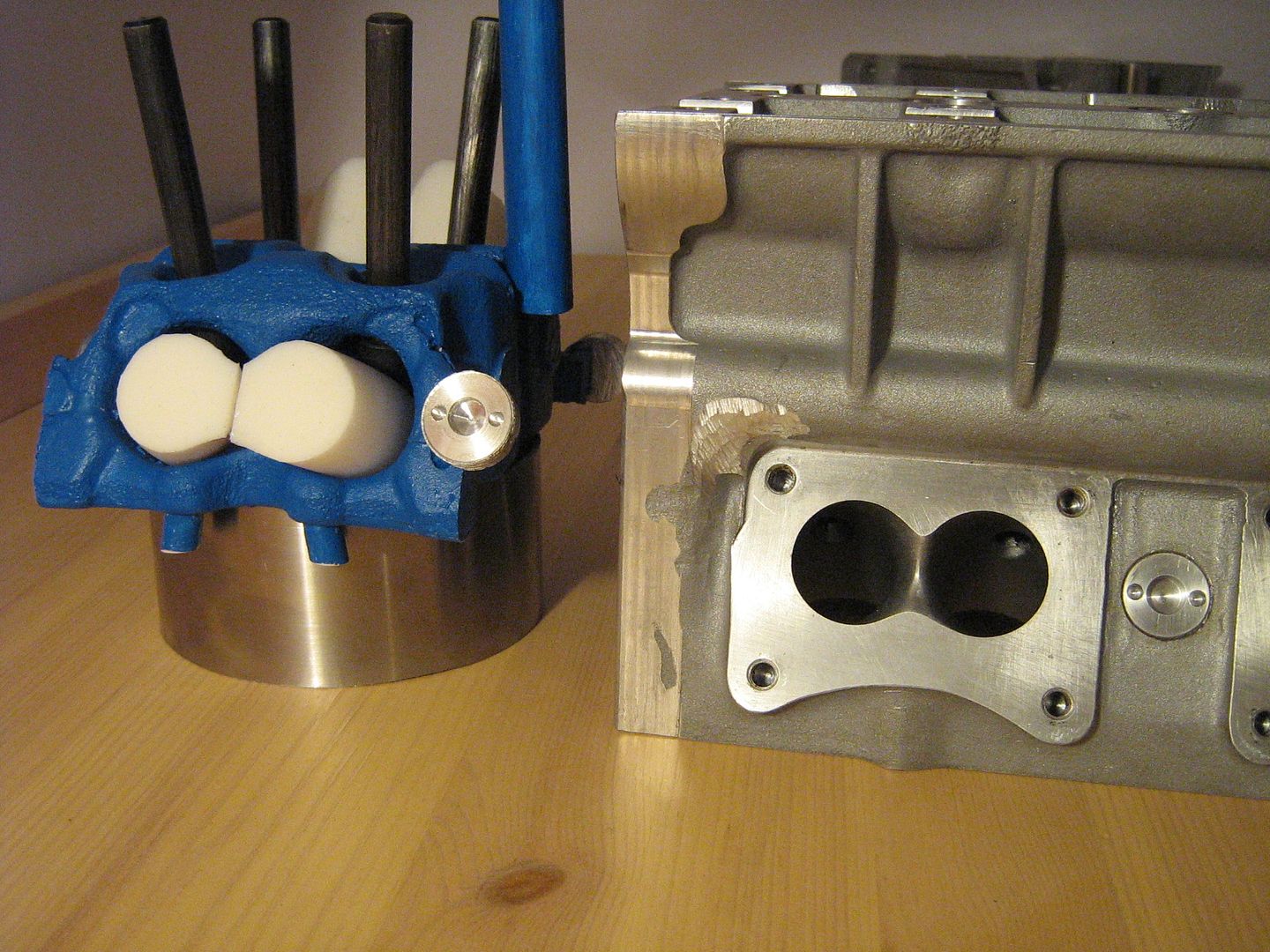
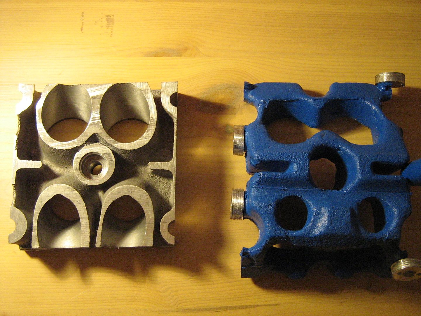
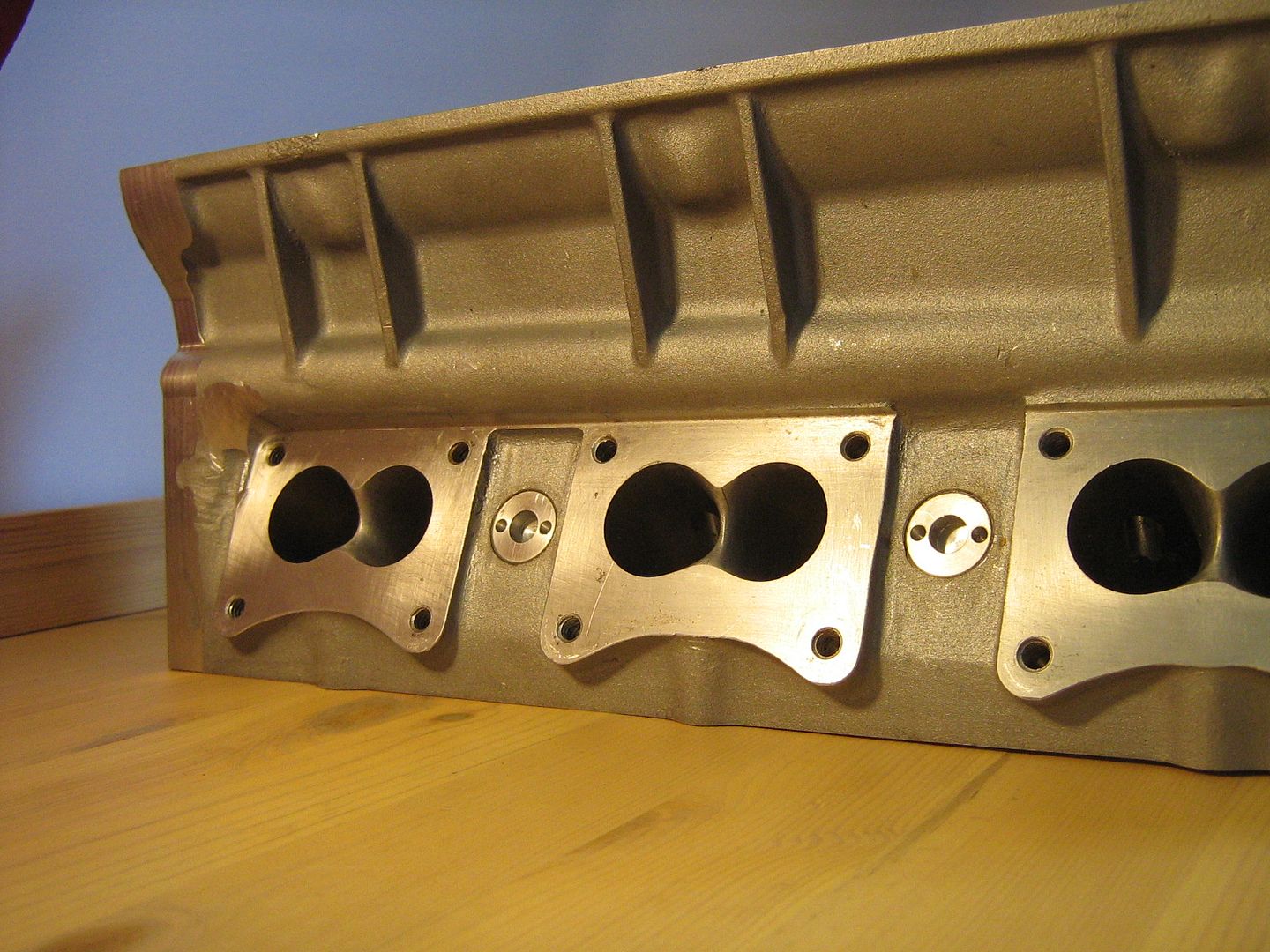
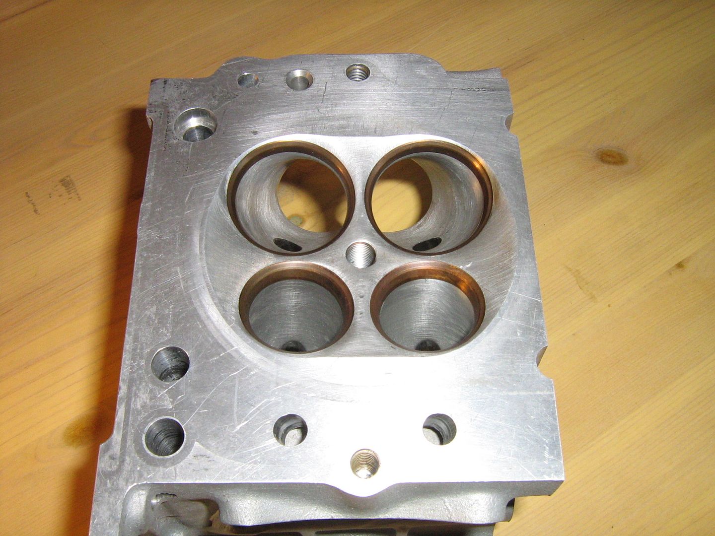
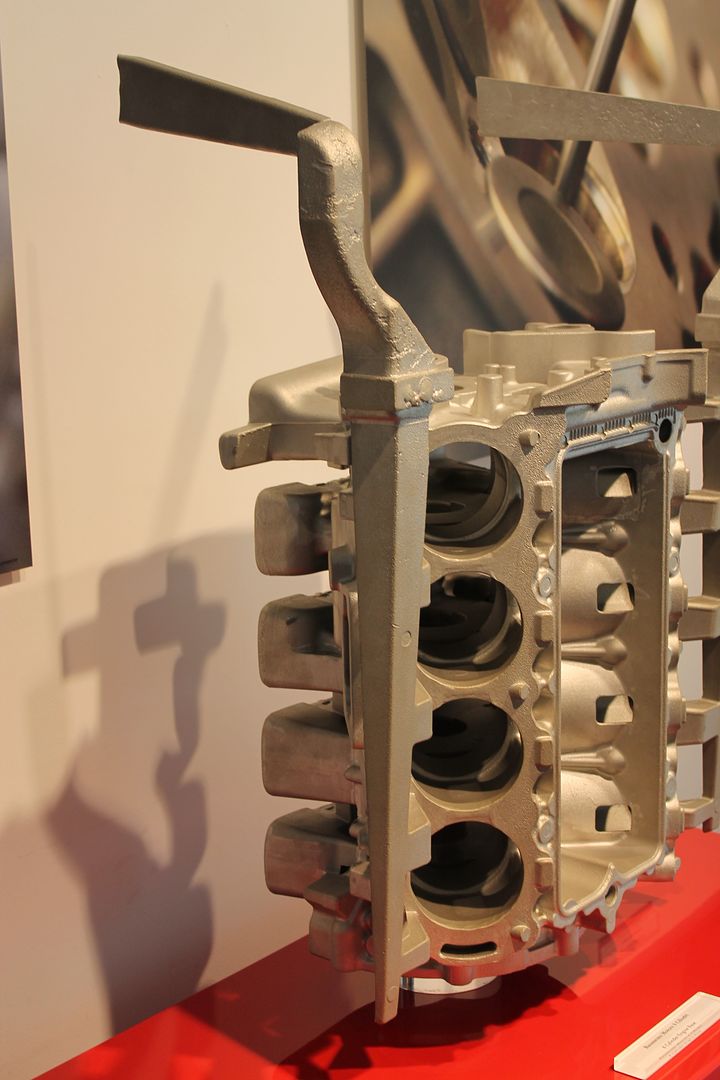
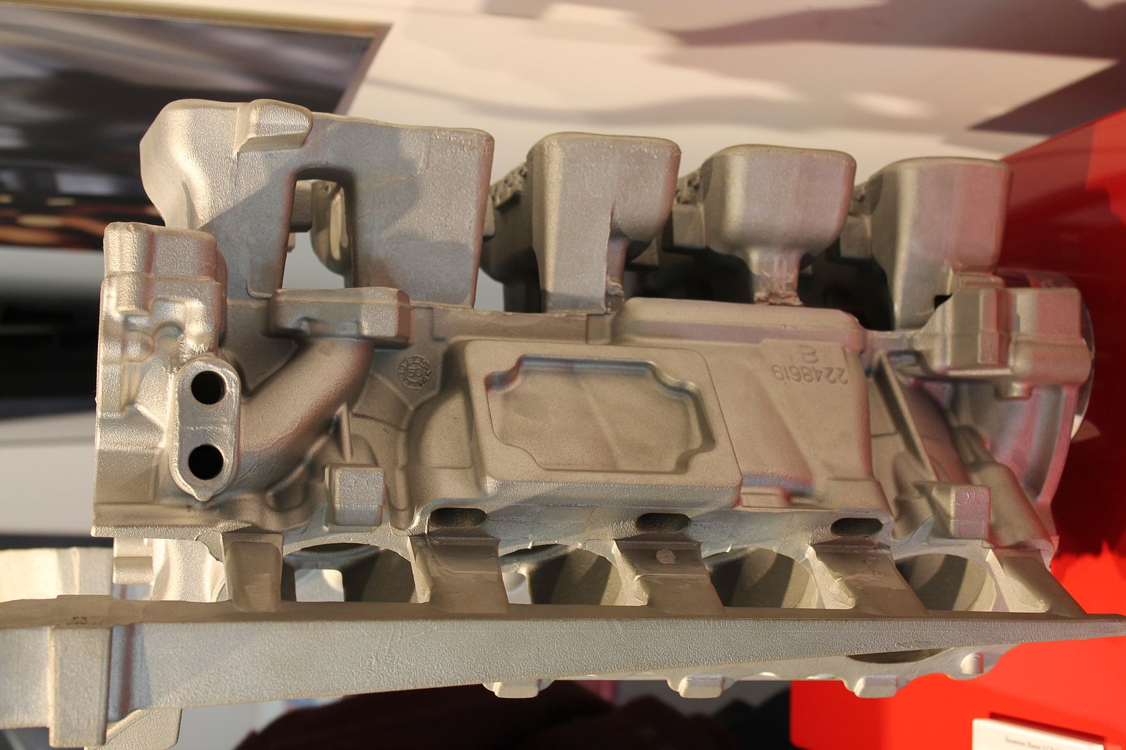
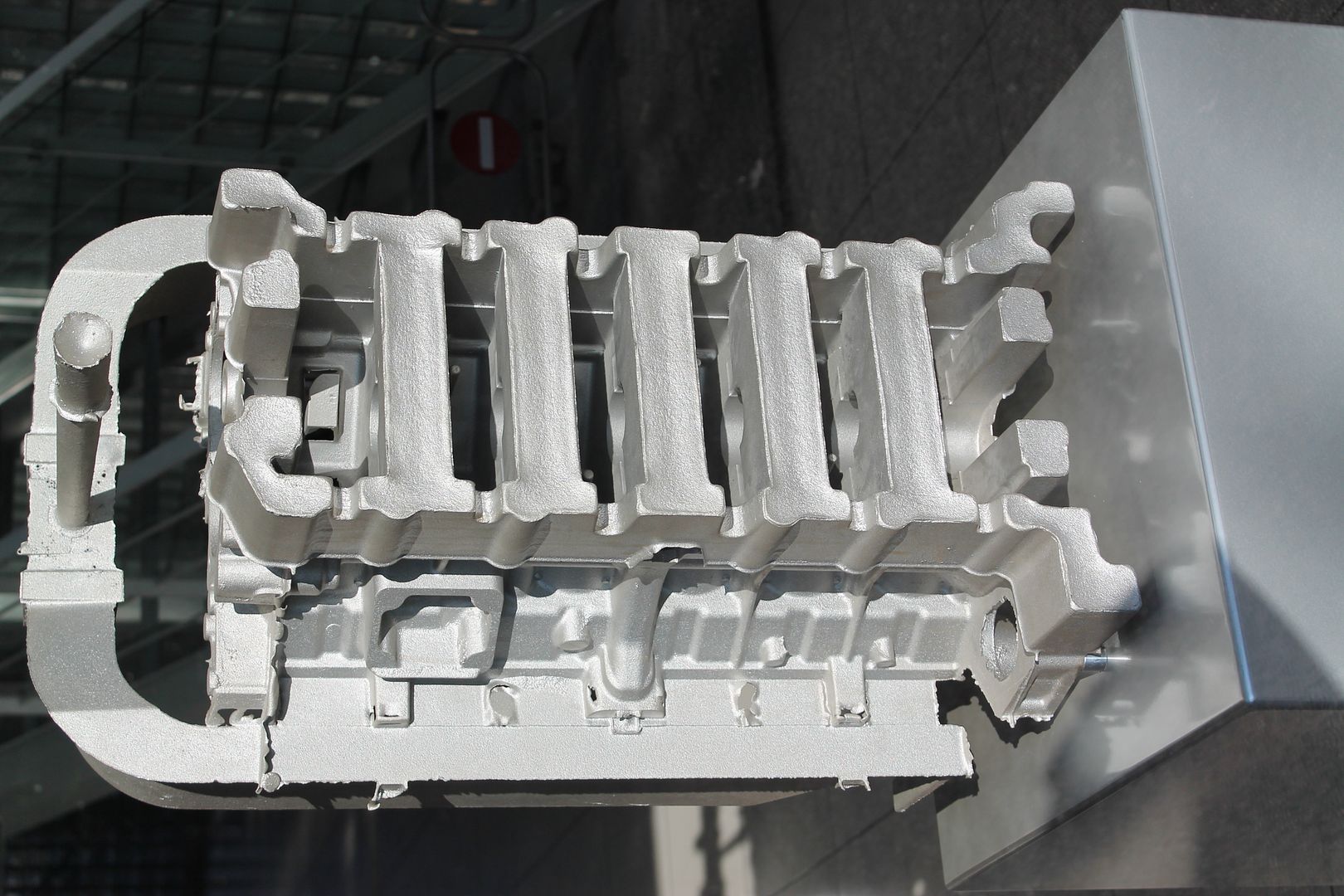
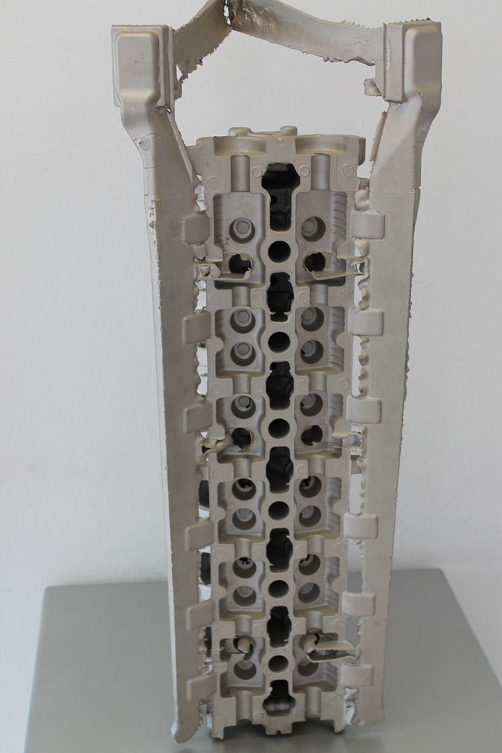
Below is a general picture of what we are dealing with, it is an image of the sectioned of the head showing basic layout with the intake or 'valley' side facing the camera. Once section - the section that the model was taken from has been omitted and in its place a model of the ports and combustion chamber + spark plug position.
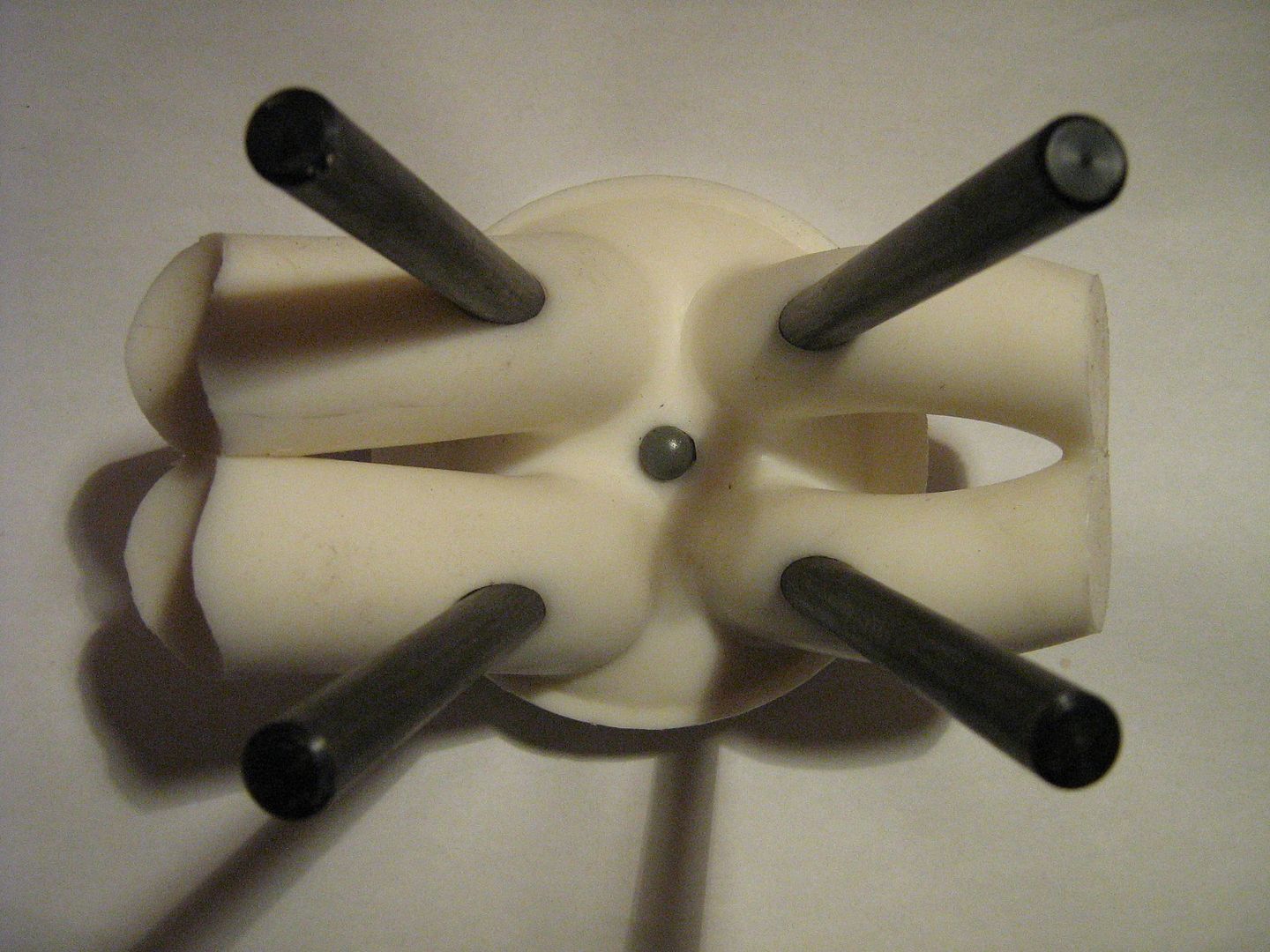
From above, showing valve angles - splayed in both planes as mentioned above. Splaying the valve angles in the less common plane creates real estate for the bearing surfaces between the tappets as well as lessening the amount of bore shrouding when the valve is in the open position. Instead of opening parallel to the bore, it is now angled slightly to the cylinder centre point.
The intake ports,

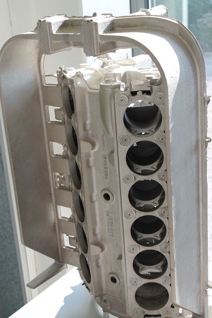
A view down the intakes, something else!

The exhausts, again, beautiful ports
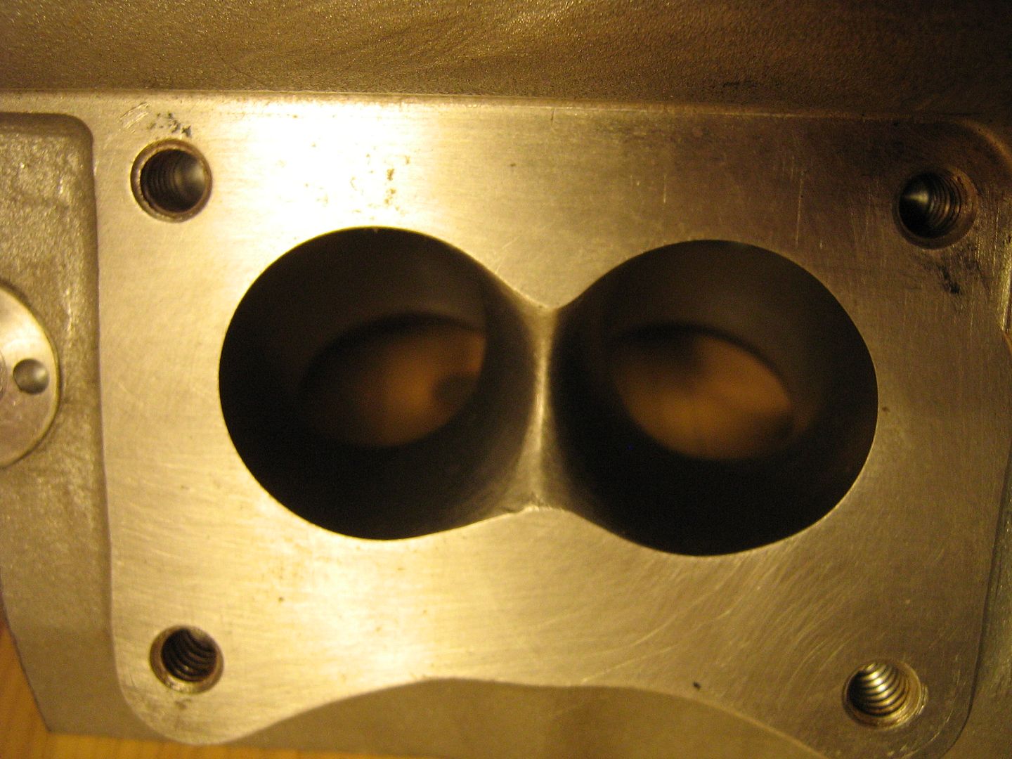
A view out the intake from the combustion chamber, all ports have a surface finish of around about 320 grit paper finish,

The seats, exhausts,
Intakes,
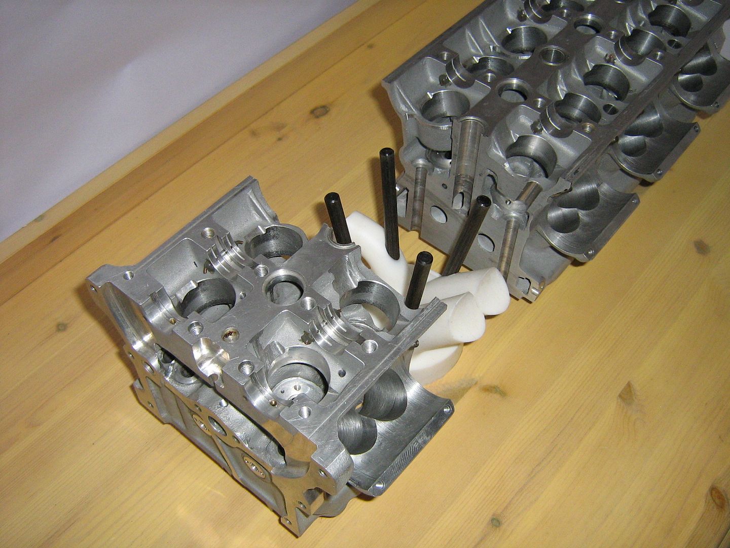
Port models,
Lets get back to the combustion chamber and the coolant above it.
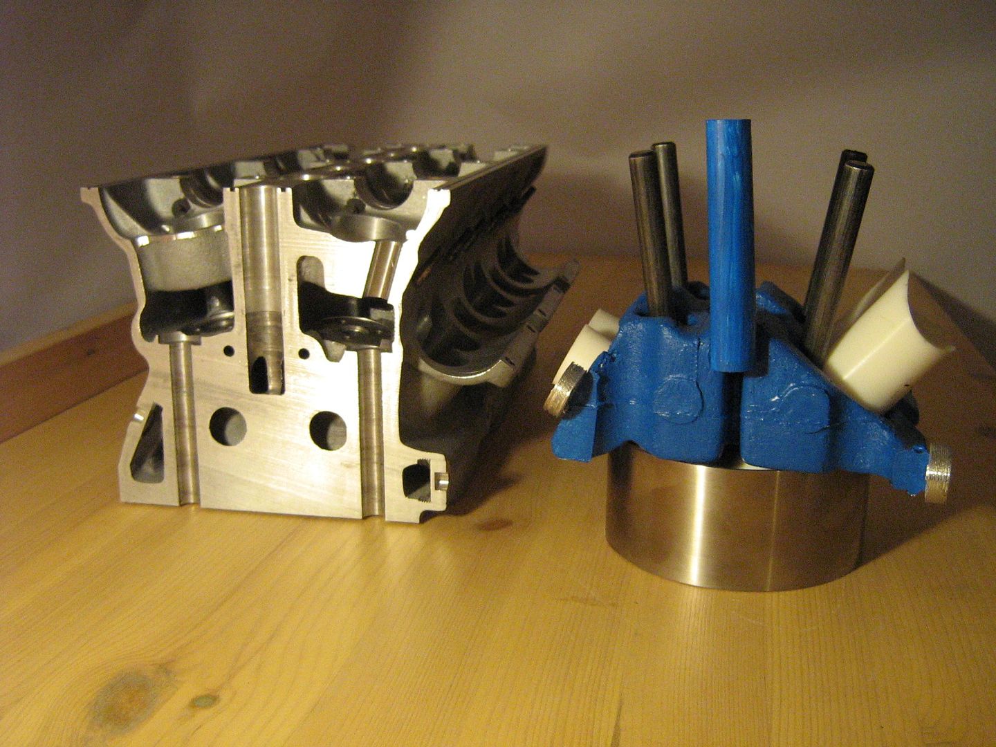
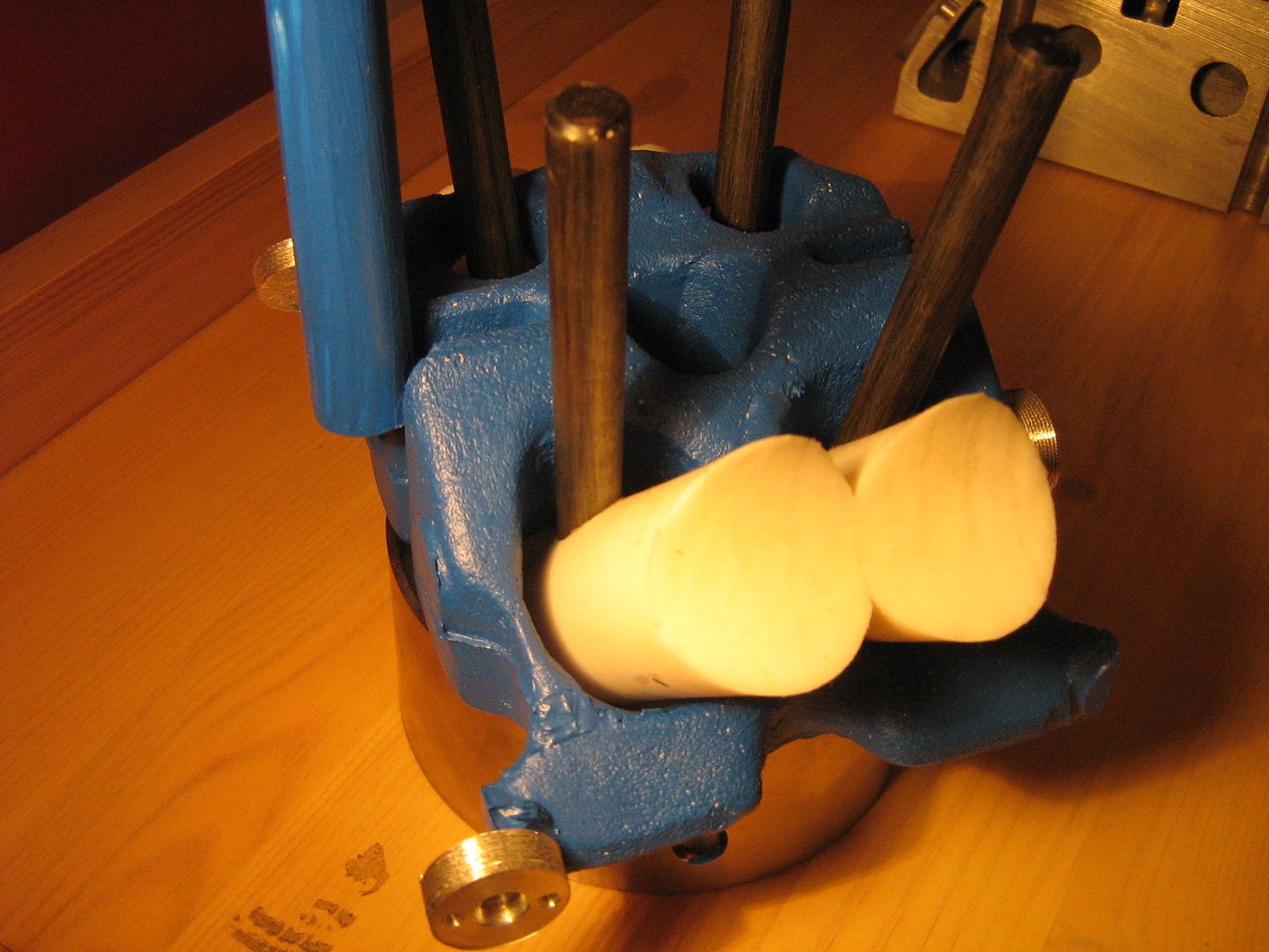
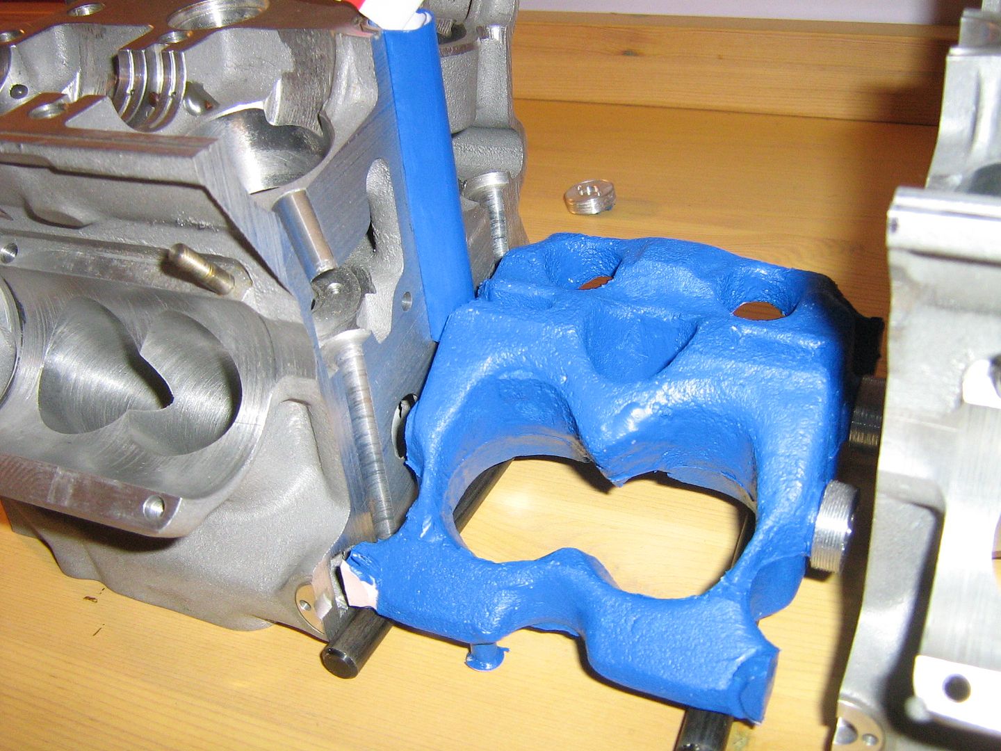
As I mentioned above, the coolant galleries above each combustion chamber are identical, the blue model below resembles exactly what the sand core would have looked like which is required to form these hollow sections within the main casting.
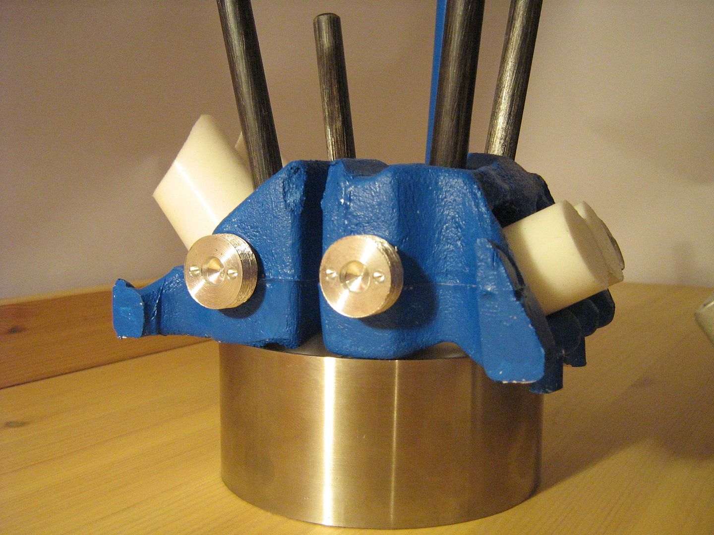
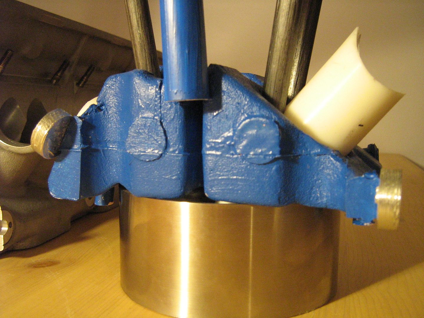
Five of these sand cores are made from the same core box, they are then bonded together and the entire unit core as an assembled item placed into the main moulds. If you look very closely at the blue model you will see where I have glued on imitation core plugs in some of the pictures. These plugs are required in the finished head as it is here that the cores extend out as slender pegs and locate into 'core prints' in the main mould. These 'core hangers' holes are dotted along either side of the finished casting and there are also two at both ends. Im guessing, or at least I would have made all the cores with these 'pegs' sticking out both sides(parallel with crank) where cores are to be joined to each other. At the time of bonding, you would leave the pegs extending out from the cores at either end for location in mould, but cut off the rest of them so that the cores could be joined to each other. The point at where each core joins the next forms communication ways between each modular coolant gallery. These can be seen as two neat round holes in the parts of the head that have been sectioned.
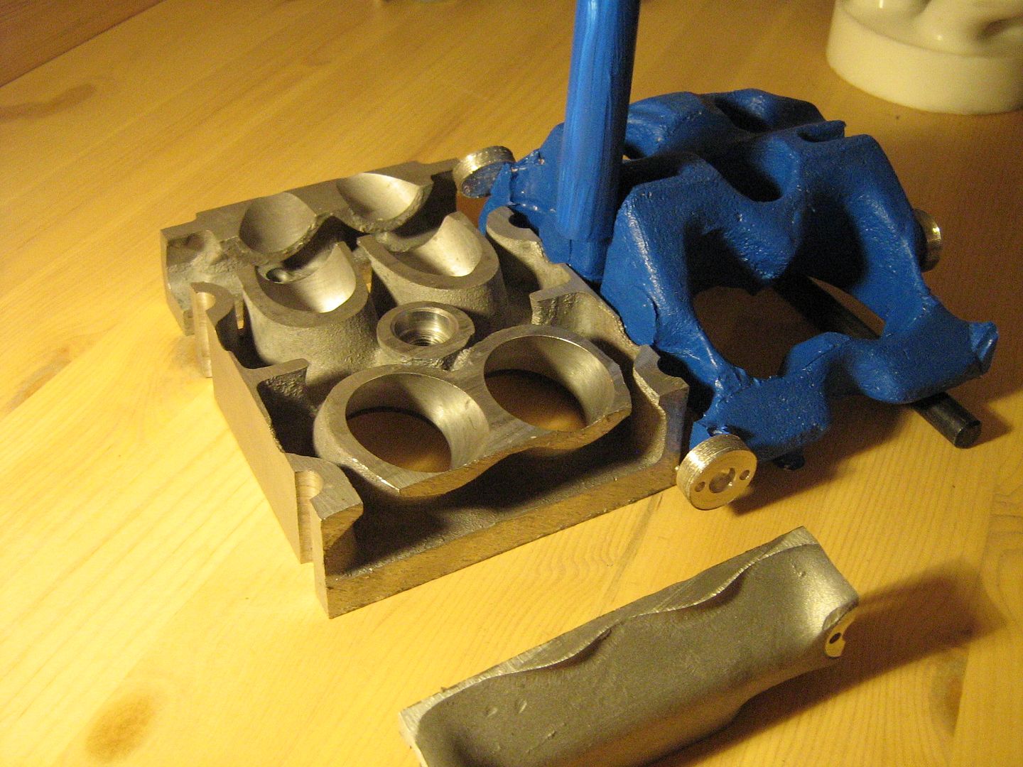
Coolant flow through the head is the conventional method used in nearly all high/super performance cylinder heads of this power output. In a normal car, coolant usually flows from the block through headgasket drillings, up into head and across all the combustion chamber roofs - exiting in one main outlet either somewhere in the middle, or at one end of the head. In this case it differs for more even flow and cooling whereby coolant flows vertically through drillings located again in the headgasket but this time flow is directed through the one piece cam cover/bearing ladder assembly through four vertical drillings. These can be seen both in the sectioned casting, and indeed the blue model - shown by the vertical blue tube. These drillings all enter a common tapered tube cast into the rocker cover. The taper ensures even flow velocity throughout its length. The total coolant capacity of the head is approx 2.45L.
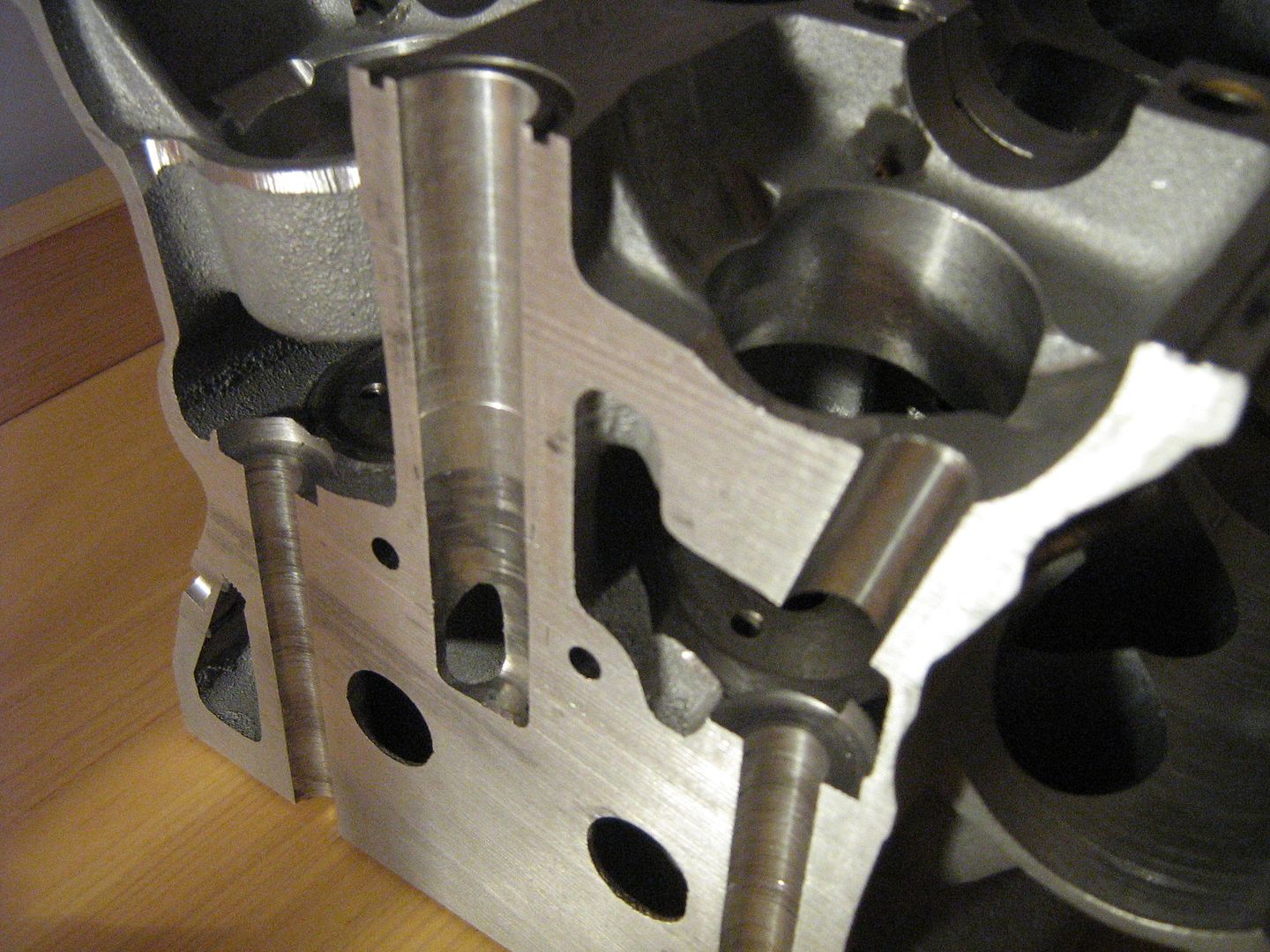
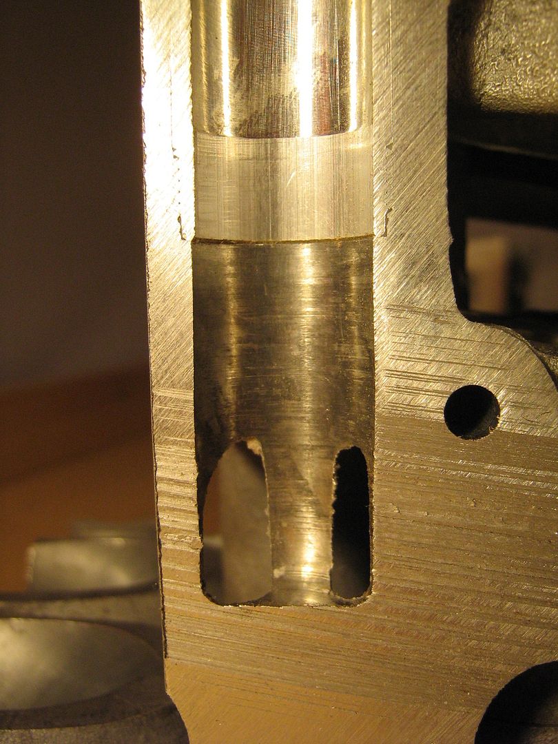
The method in which these vertical drillings intersect with the coolant areas is also very clever. If the cores were to have these vertical slender tubes at time of manufacture they would be extremely fragile, so instead, the cores are made without these tubes. Once the casting is ready to be machined these vertical tubes are finished bored deeper and break through centrally between each modular coolant gallery as shown below also. These vertical drillings are lined with thin tubing after to form sealed drillings since the drillings pre lining are open to the main cambox/beam for a small portion at the top since the beam section in the centre of head is actually hollow.

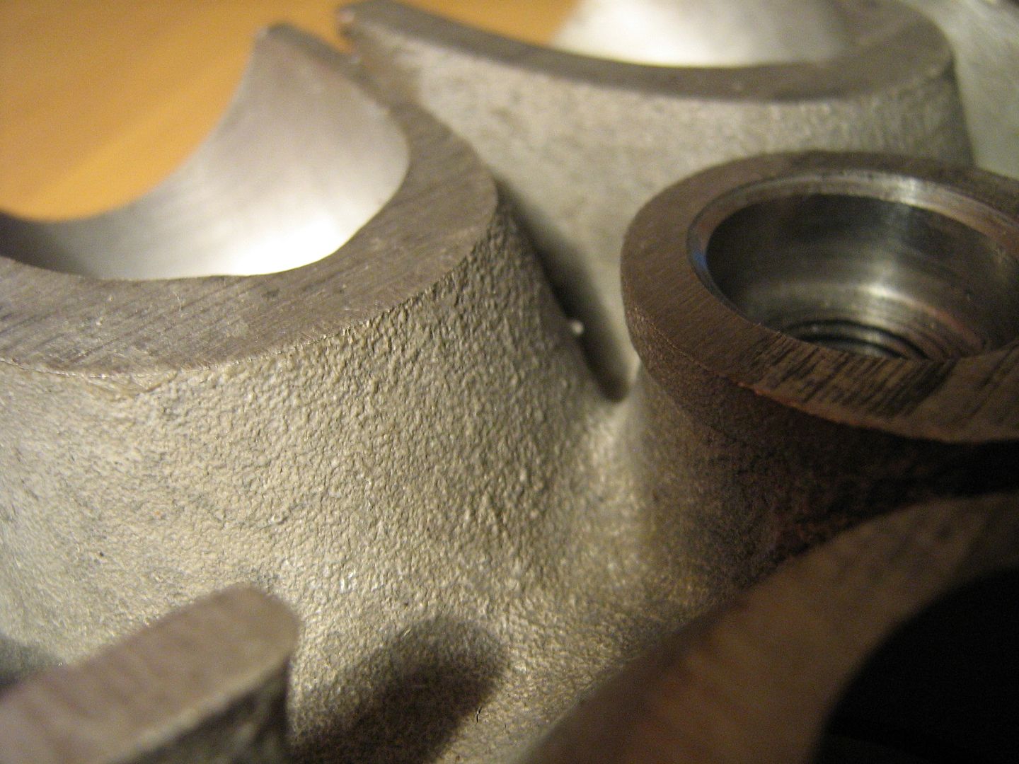
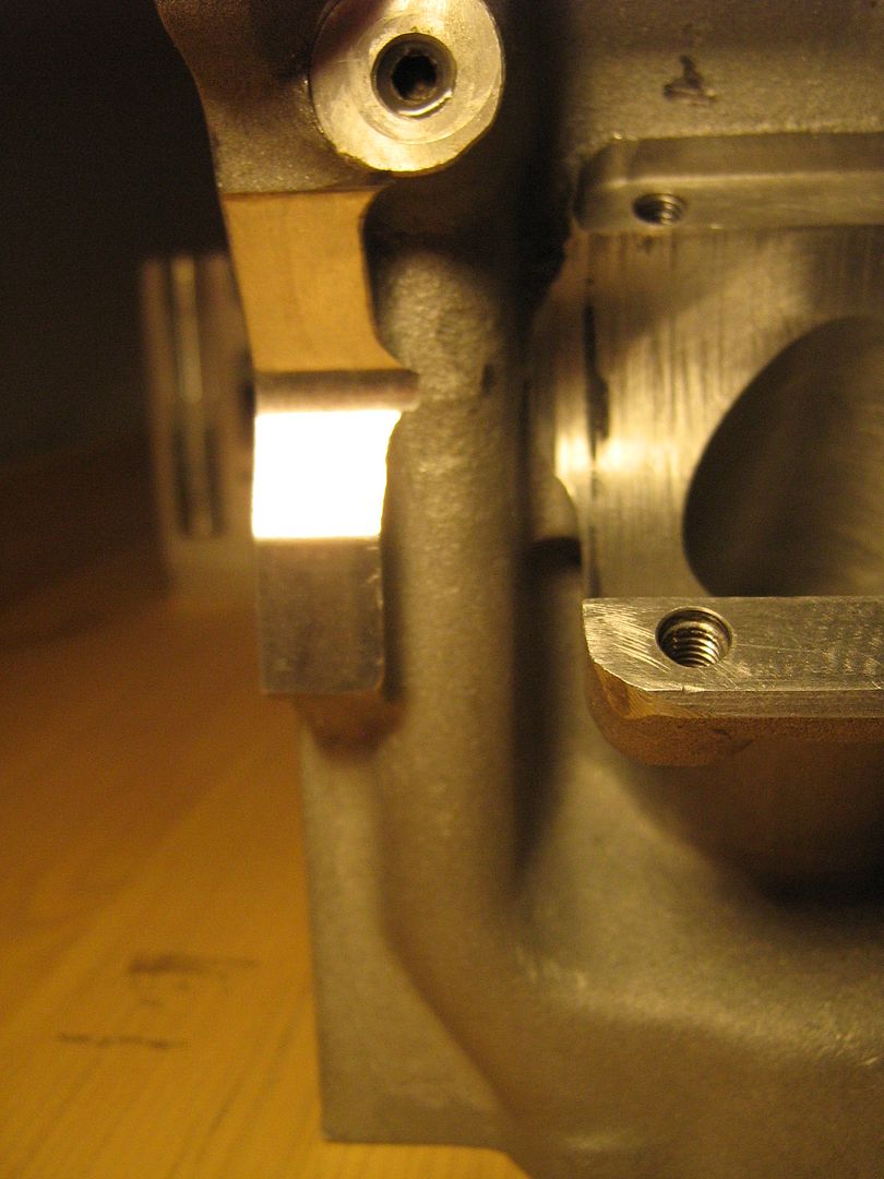
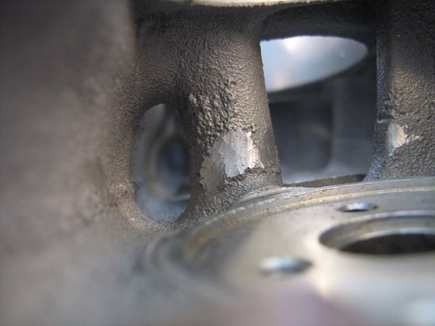
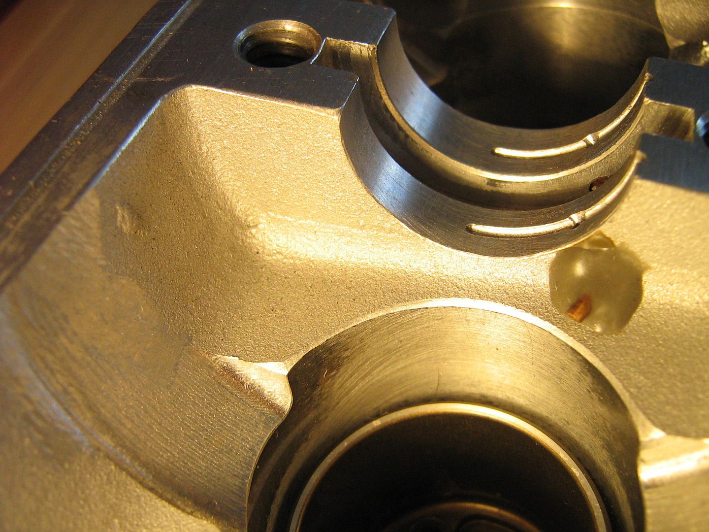
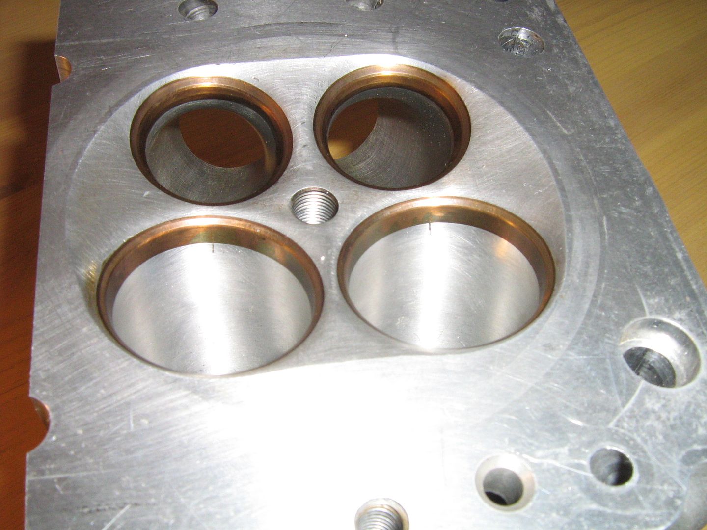
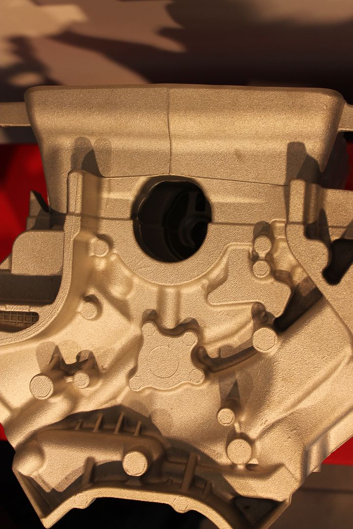
A rare shot of such a tidy casting area around the spark plug location. Notice how much room there is for coolant to circulate between the exhaust port and the sparkplug. This is the most important area when cooling is concerned above the chamber and is also why they run such tiny plugs,
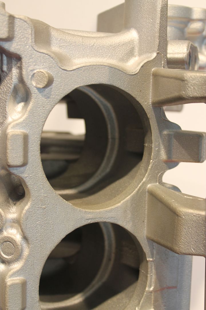
The vertical coolant channel showing liner tube and break through section into gallery at base,
A view from inside the gallery, the flow is split by the central divider/head face support section,
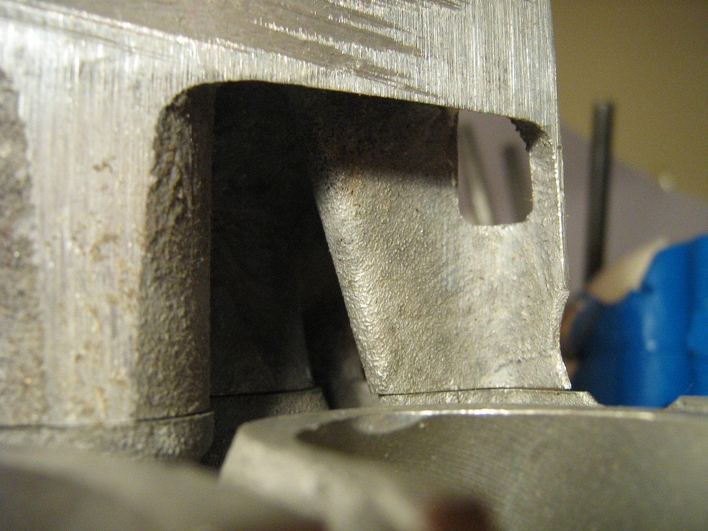
Another point to note in the image below is to consider the head mounted in its working position, in this case rotating the parts below to the left - the position of the vertical drilling in the gallery ensures no trapped air at the internal gallery roof area,
Coolant flow through head-gasket area is given priority via two drillings beneath the exhaust ports, only one smaller drilling exists between the intakes.
Moving onto the oil system now. The oil is pumped from the block up into the head and from there into the hollow camshafts. Unlike some cylinder heads where hydrodynamic oil films are formed by supplying pressurized oil to the journals via internal drillings within the casting, this case is different.
Here oil is supplied to each journal via drillings in the camshaft itself. This has several advantages in that it ensures a constant supply to each journal, it does away with complex drillings within the head which take up room and it also provides excellent cooling throughout the camshafts length.
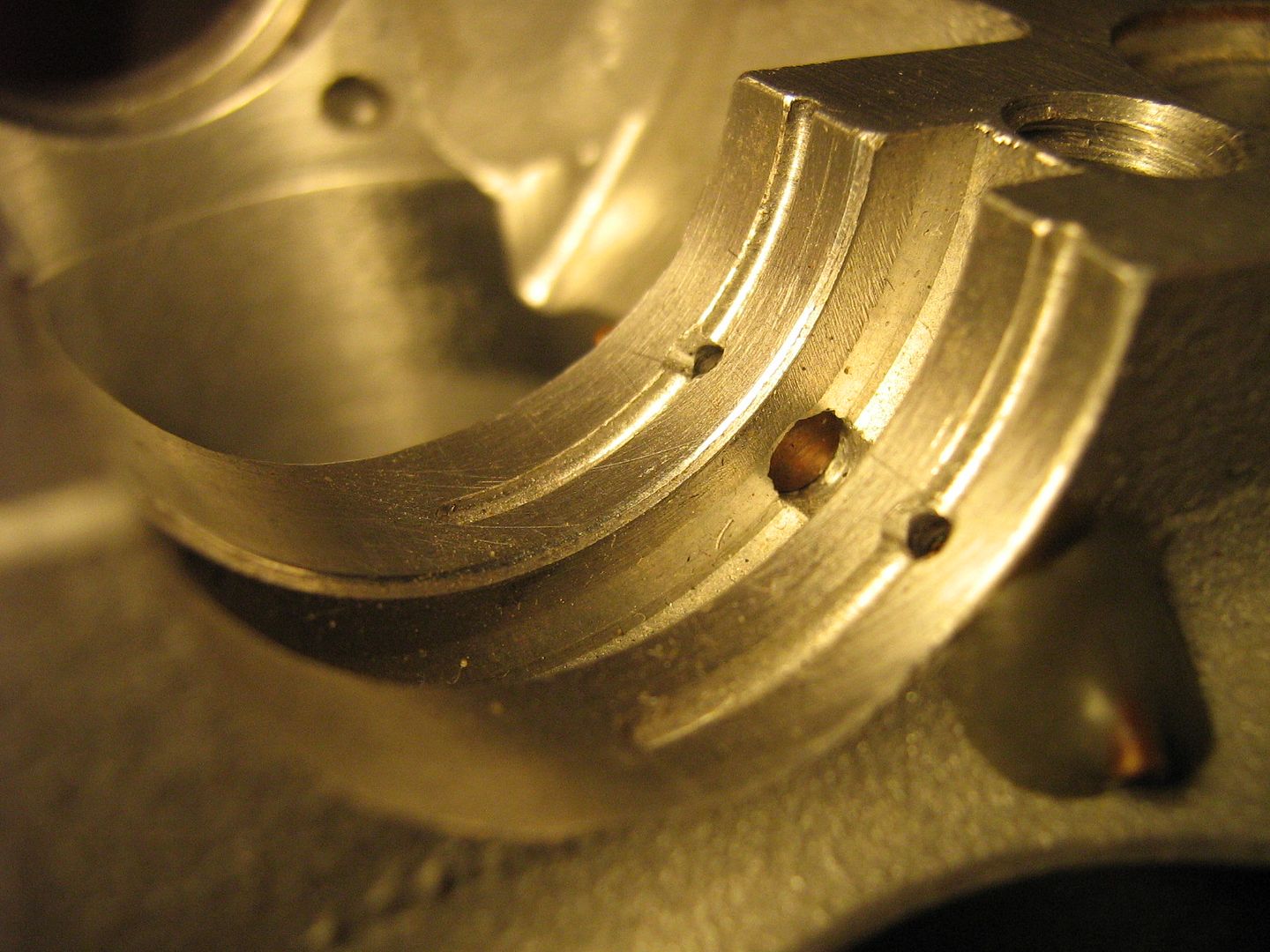
The head features oil squirters also which take their supply from a groove in the lower cam journal. These take a small amount of pressured oil from the cam via a small drilling - the spray is directed at the tappet face where the cam lobe presses on it.
These squirters are fitted and bonded into a drilling which runs the full length of the head. A full drilling is the easiest to drill as access is extremely limited for chuck/collet holder clearance should they have drilled each hole individually with a right angle head assembly.
The entry and exit locations of this drilling are simply closed with adhesive either end.
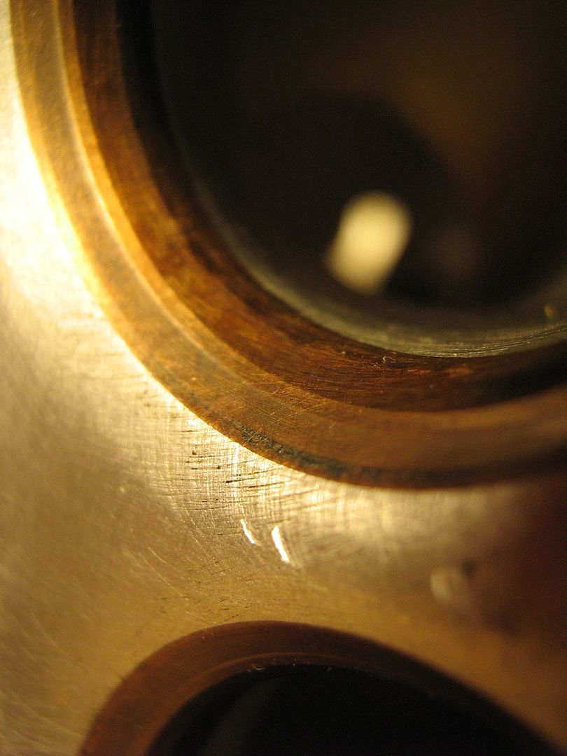
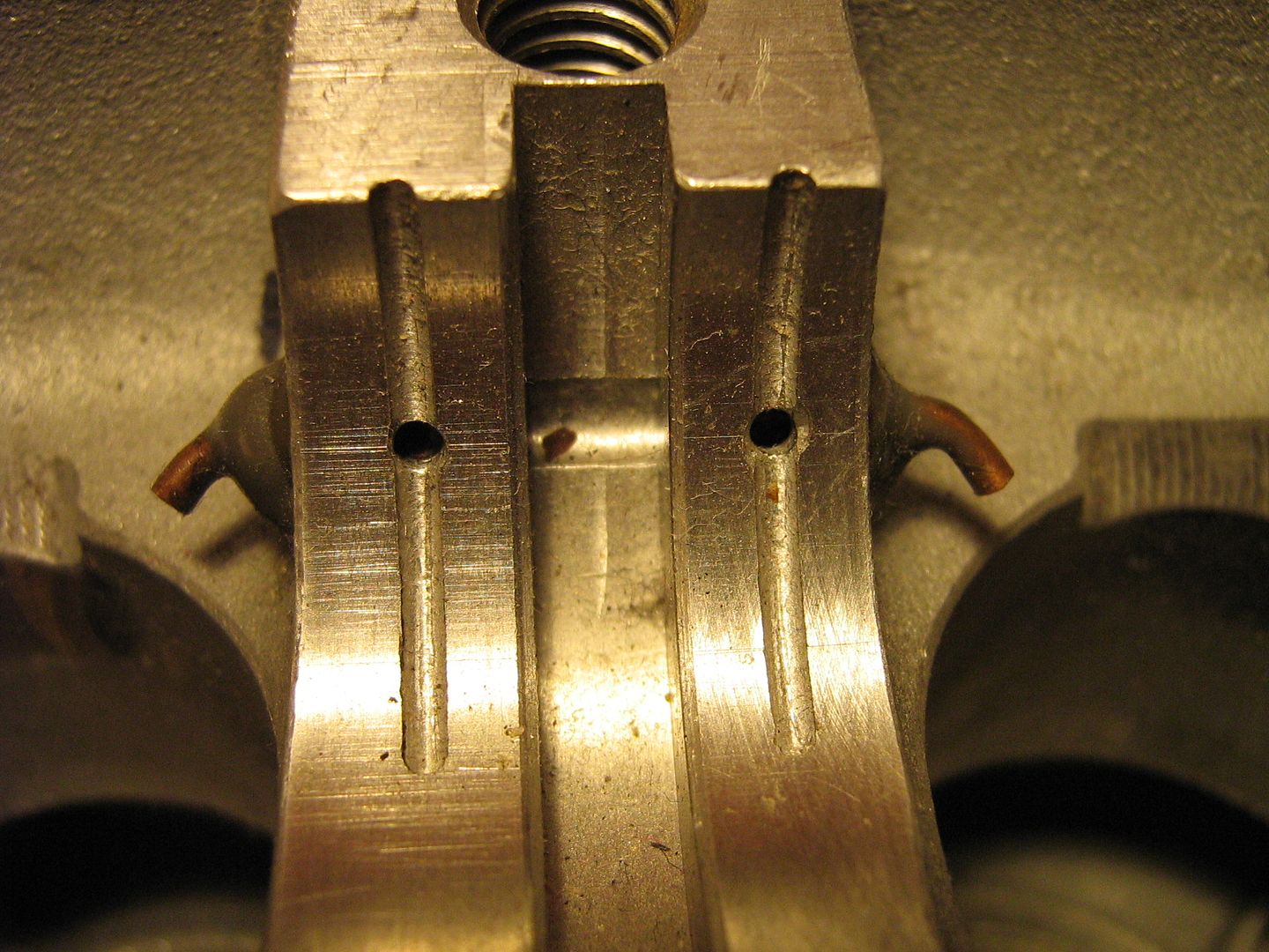
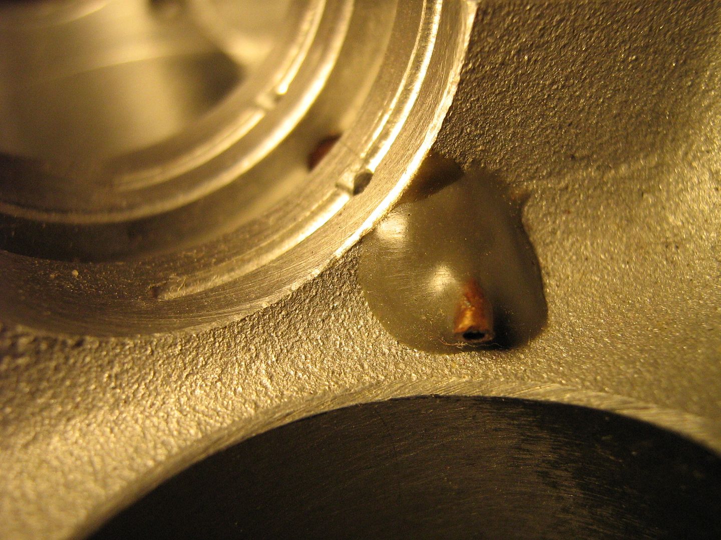
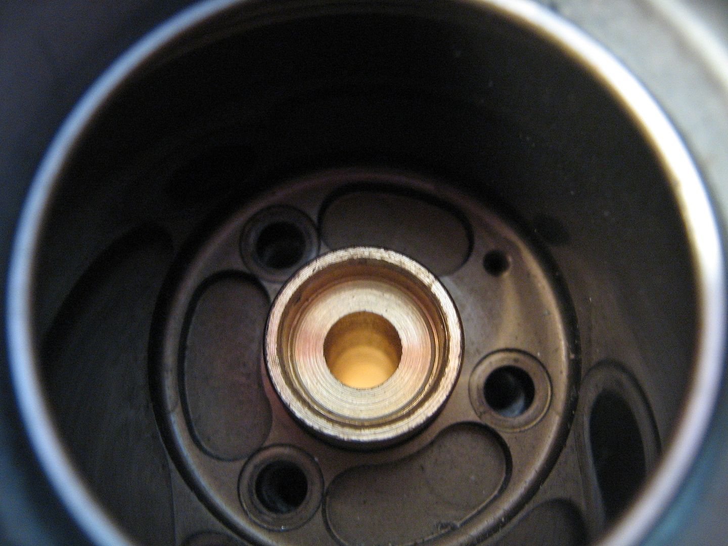
Below are a collection of pictures displaying what is described above. The first picture the shape made by the oil way up to the cross drilling that connects both cam supplies,
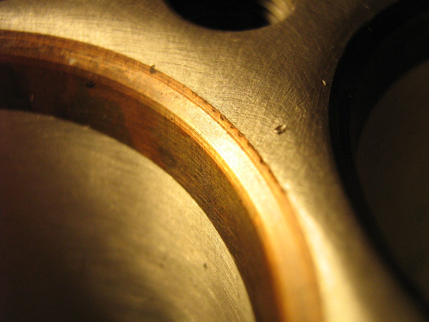
The cross drilling is just inside this section,
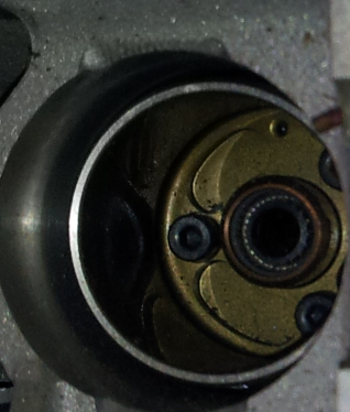
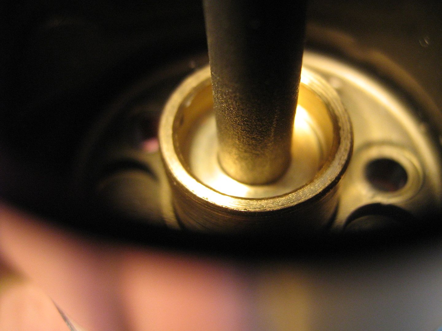
The oil enters the cam here through an orifice. Im guessing the sizing of this orifice is done in the r+d phase as it is a separate part and threaded + staked in after.
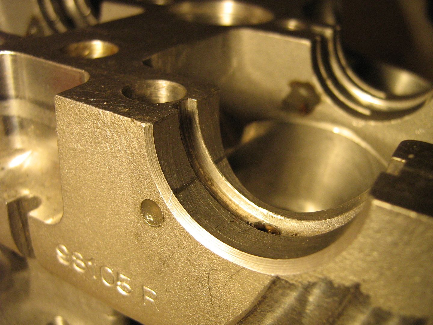
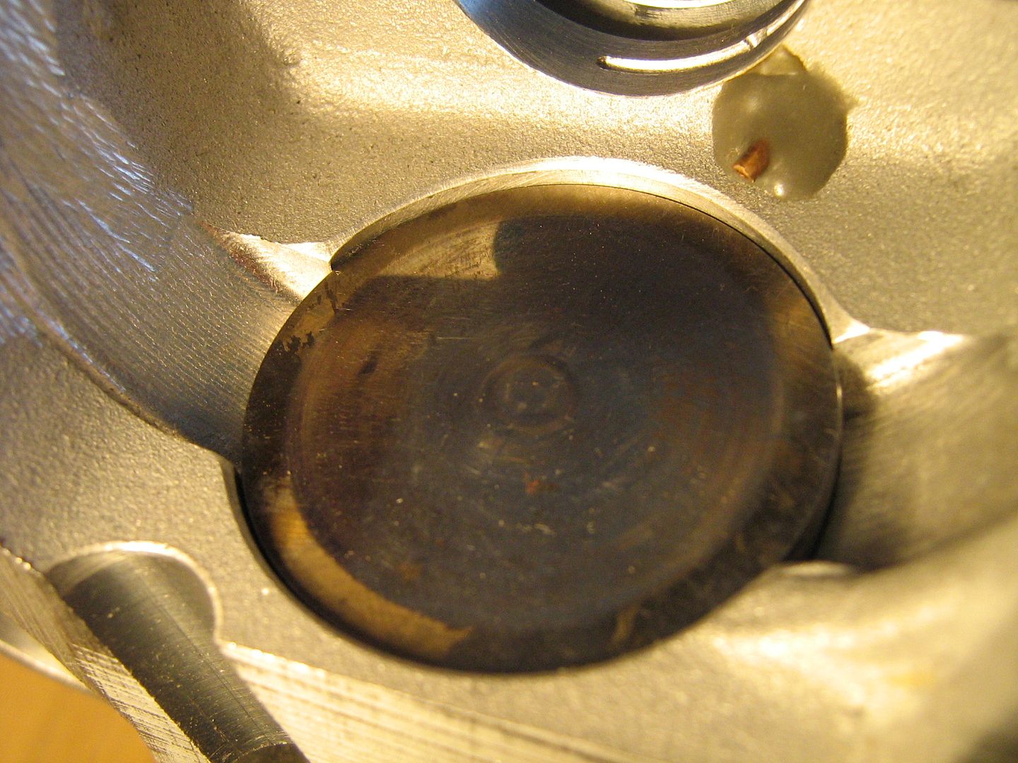
Here is the bearing that controls endfloat of the cams. Its important to note here that the main large groove in the middle is just for axial positioning and does not supply the oil squirters. These are fed from the smaller grooves and holes in the actual journal surface. The squirter rears are not open to this large central groove.
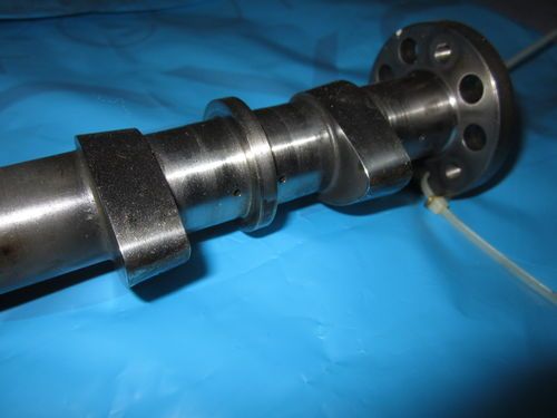
A shot of the cam showing axial endfloat ring, as well as the main supply hole at the end(hard to see) and also the angled lobes required to activate the splayed valves.
An overhead shot showing other journals and general layout,
With regards oil drain from the head, and its flow back to the sump, two holes at either end of the head look after this. They are placed on the exhaust side of head which is the lowest side when the head is in service. Two very slightly ramped drains with their highest points in the centre of the head directs oil to both these drain holes. The ramp down to the holes is very slight and not much more than 2-3 degrees from horizontal.
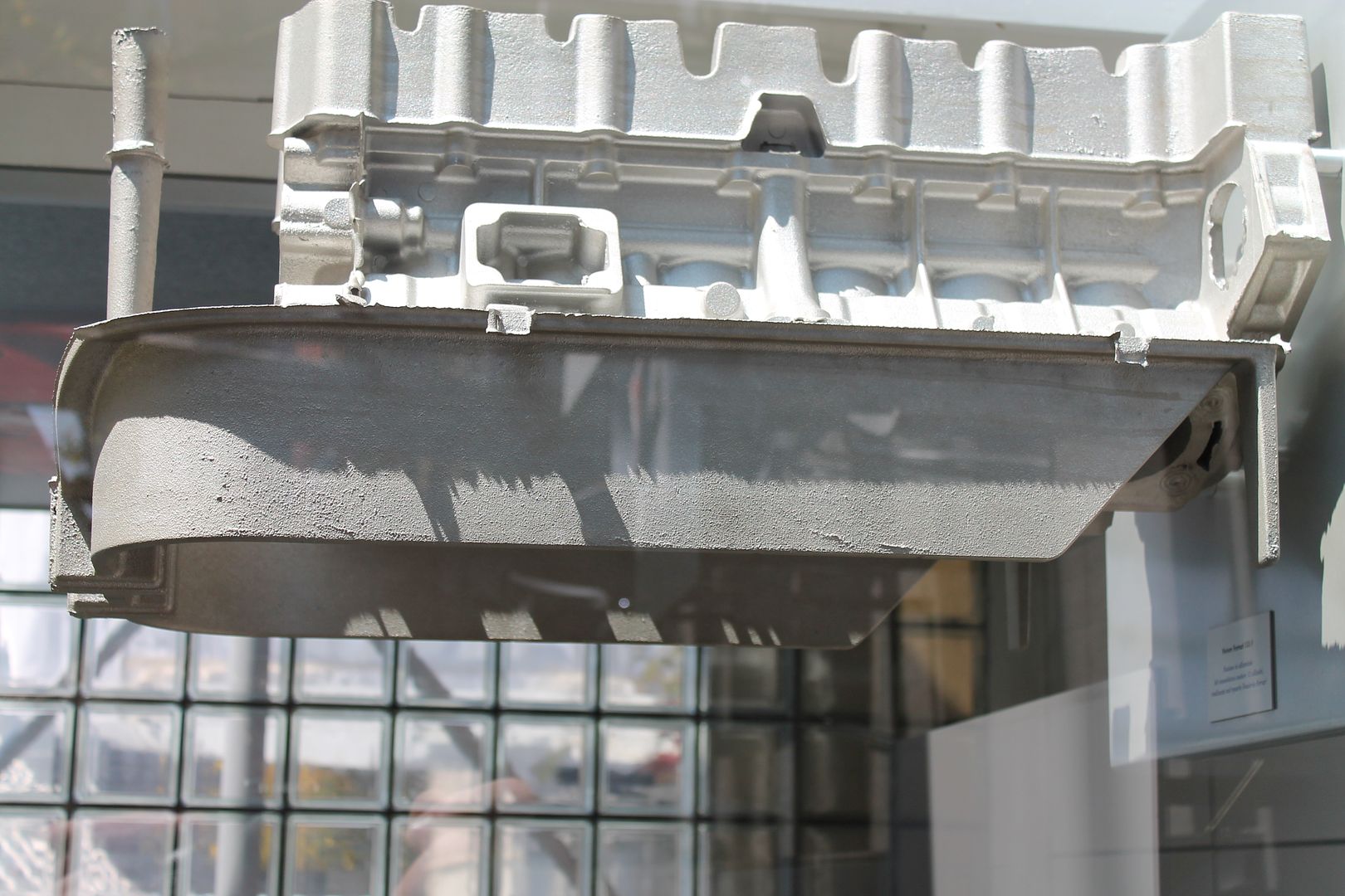
Here you can see the outline of the drain path from the outside and its protrusion outwards at the far end which translates to a downwards slope once head is in service and angled on the block,
The drain hole on one end,
An inner shot along the drain, notice too the cast pillar which is directly under the camcover bolt - tying the cast structure together and sharing loads,
The cam cover locates onto head casting with a solid steel dowel either end - Same in the cast of the heads onto the block itself,
A Quick mention of the head studs and securing nuts. These are normally a major problem in terms of room required for acess to them in order to remove the head. In this case everything has to come out in order to undo the huts and remove the head. Once the cams and pneumatic valves have been removed a crows foot spanner is used to undo nuts as they are not directly accessible with a straight socket. It is similar to some Ferrari production engines in this way necessitating the use of a special tool.
This image gives a good Idea how access is gained through the tappet bore with the crows foot spanner,
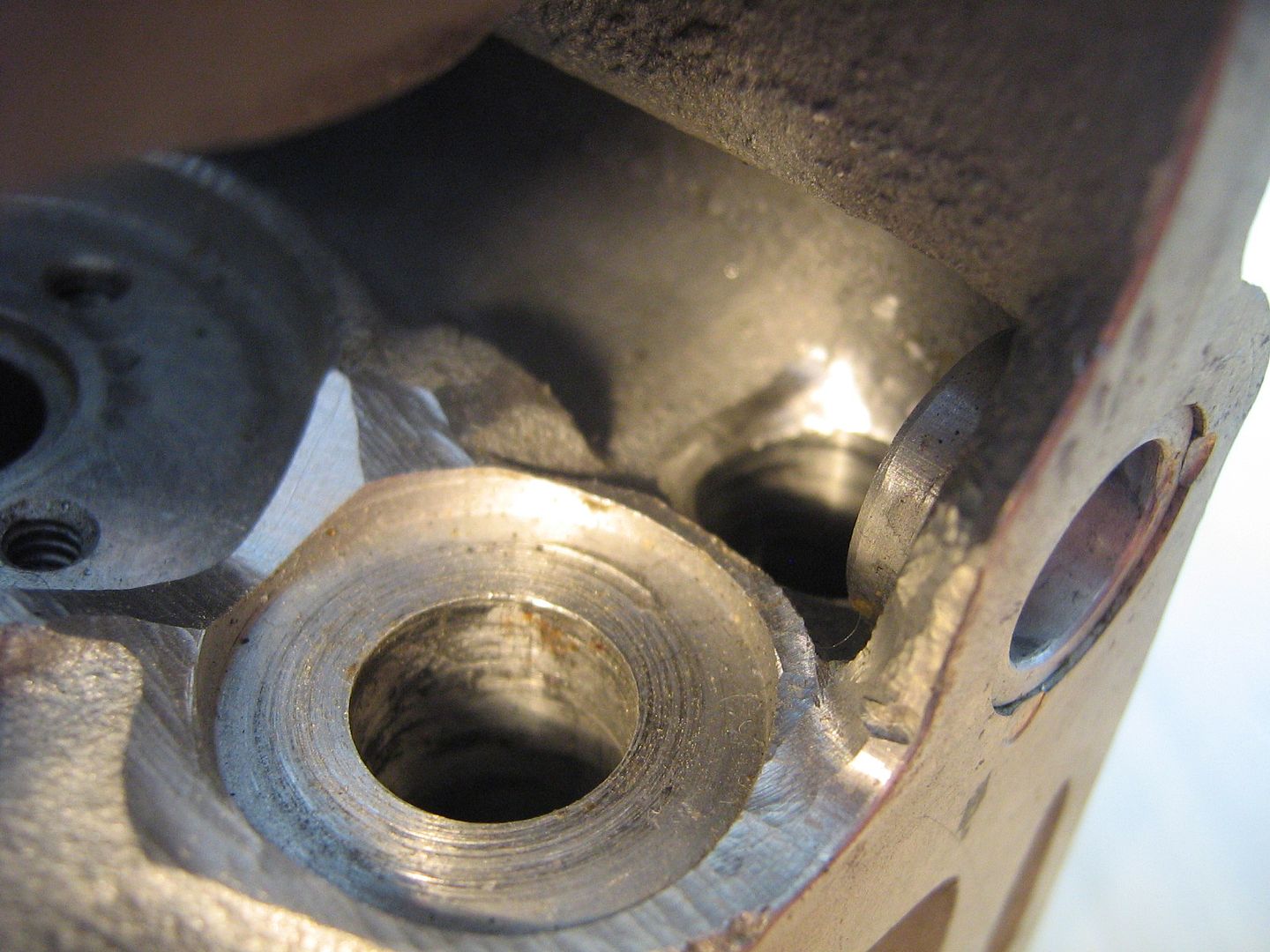
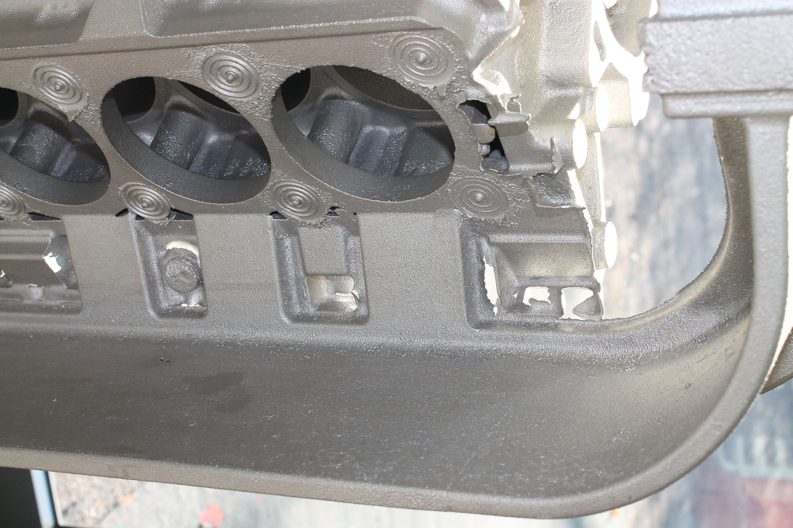
Onto the pneumatic valve train, this head uses a barrel and piston type pneumatic arrangement. The barrels are pressurized via two main drillings parallel with the crankshaft. These main drillings can be seen below exiting at the tub end of the head,
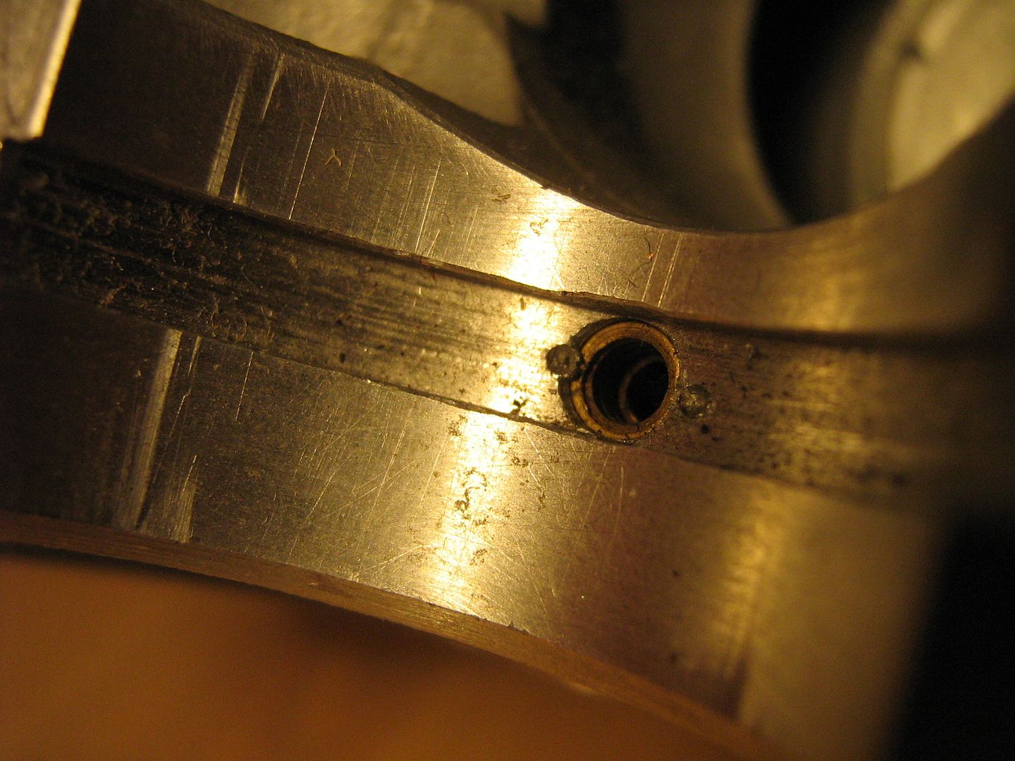
And again mid way through the head, if you look closely you can also see the vertical drilling leading from the barrel counter-bore into the main drilling,
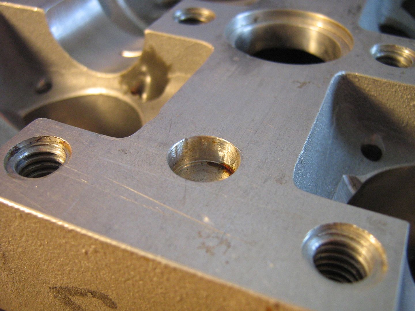
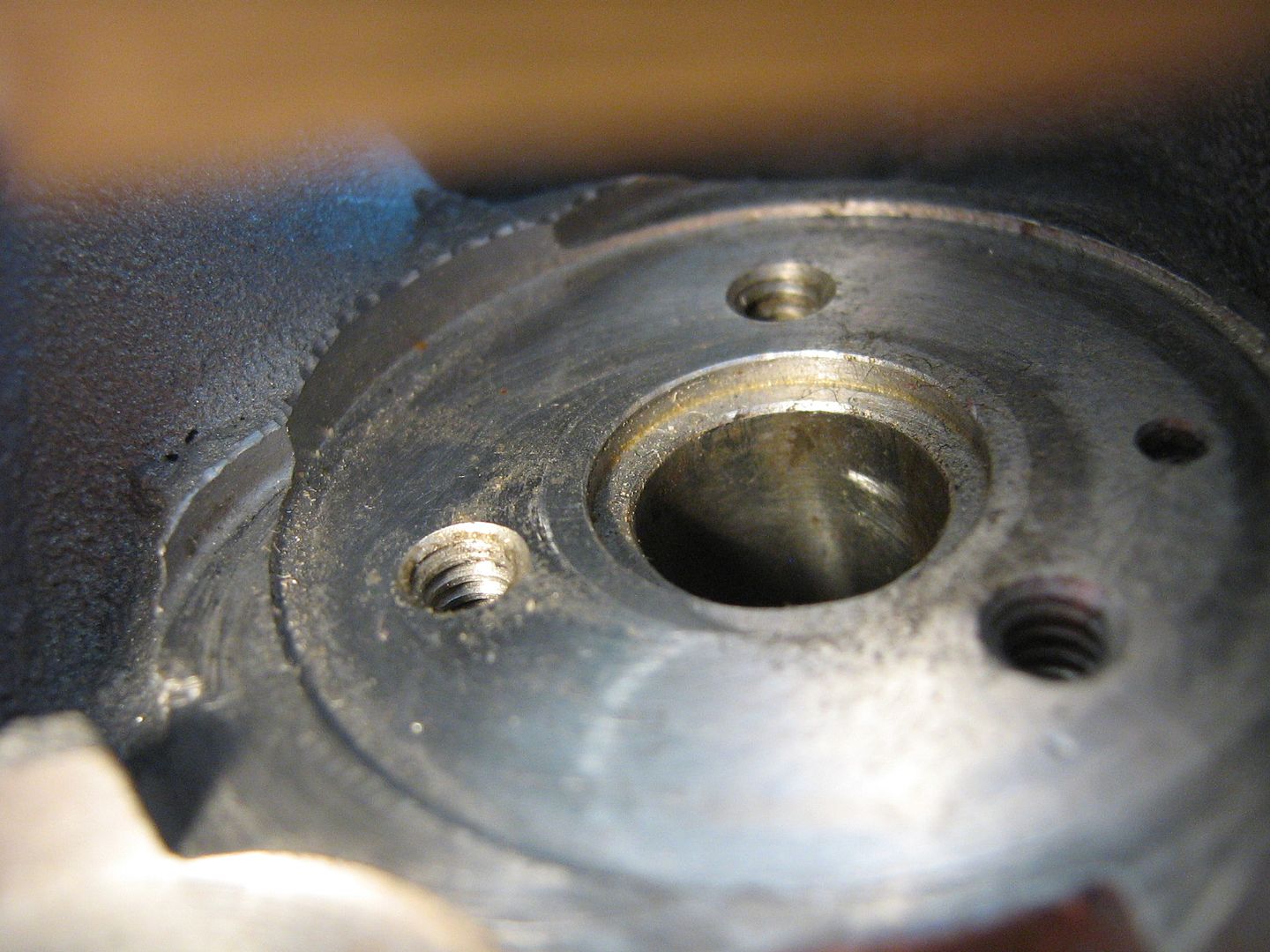
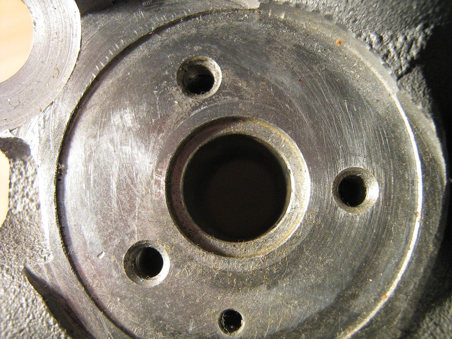
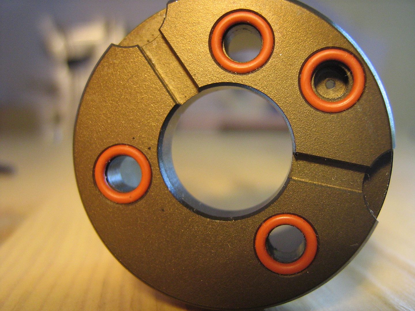
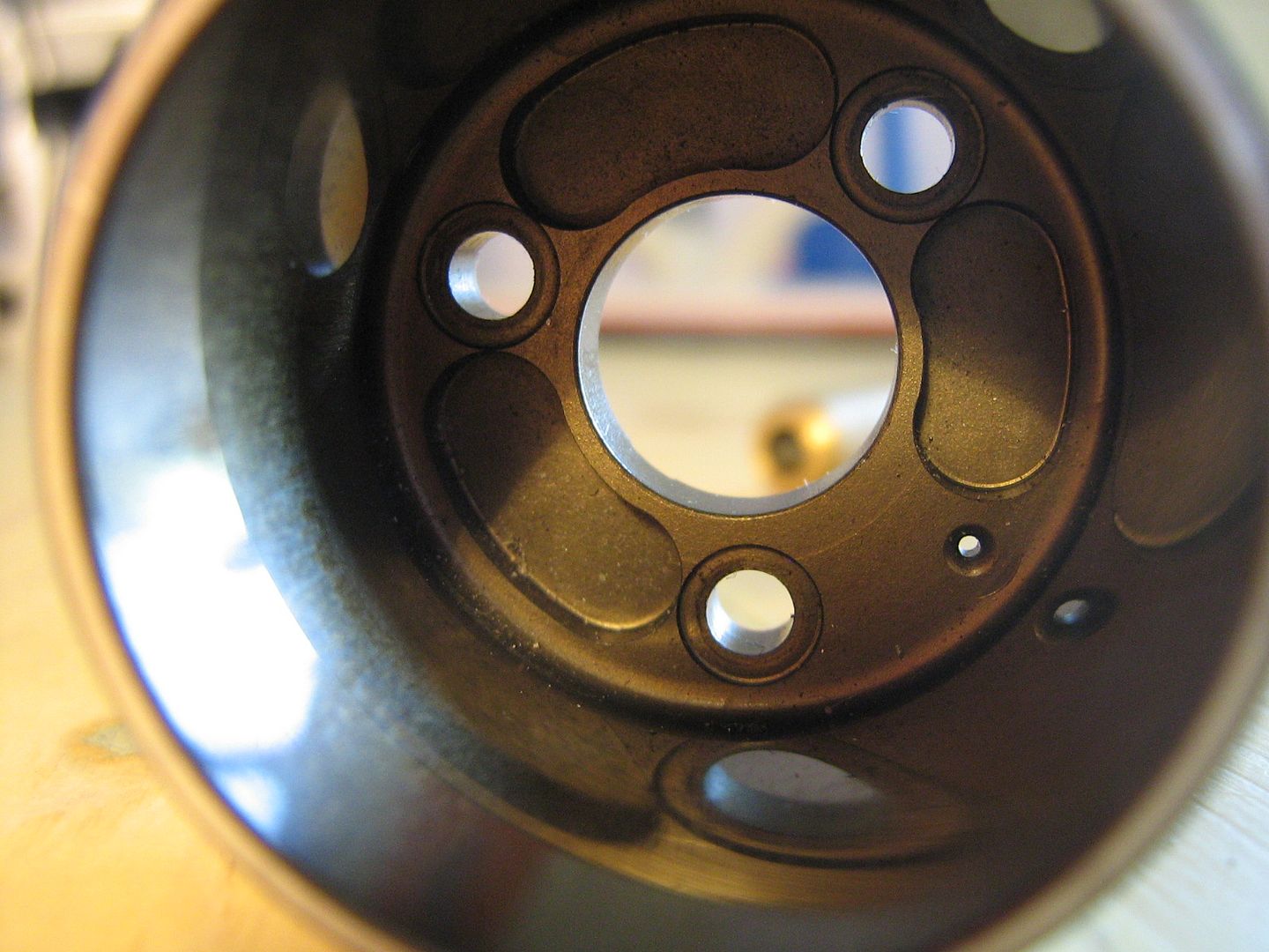
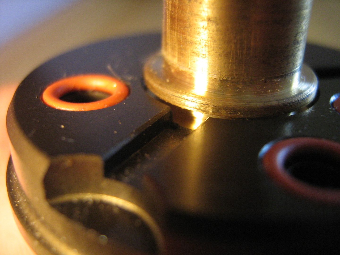
Here is a closeup of the counter-bore itself, showing the three tapped holes for fixing the barrel as well as the air supply hole/drilling,
Here it is with the valve guide pressed in, notice the small groove in the guide with the O ring above. Oil enters this groove via cuts in the base of the barrel where it flows around the guide groove and exits out another drain cut in the barrel base pictured below,
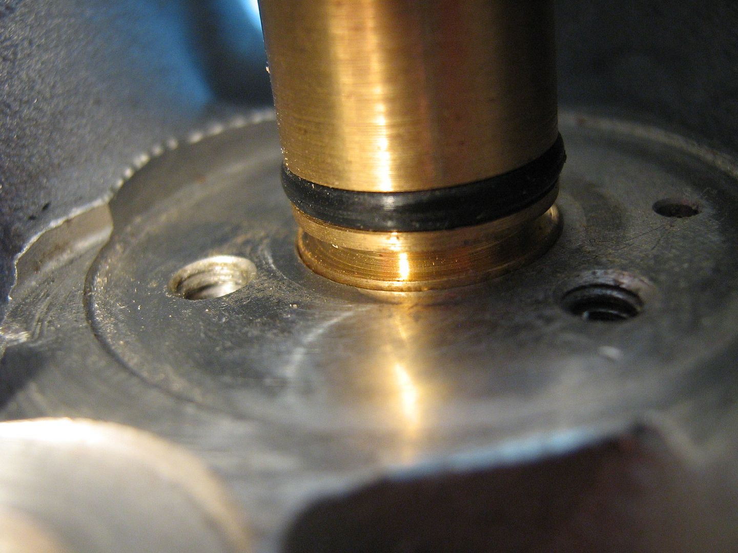
There is a small entry point drilling in this groove needed to supply oil to the stem for added cooling/lubrication,
Below are the grooves mentioned in the base of the barrel, one directs splash/run off oil to the stem, the other is the drain. When installed one groove faces up hill and collects the oil directing it in towards the guide,
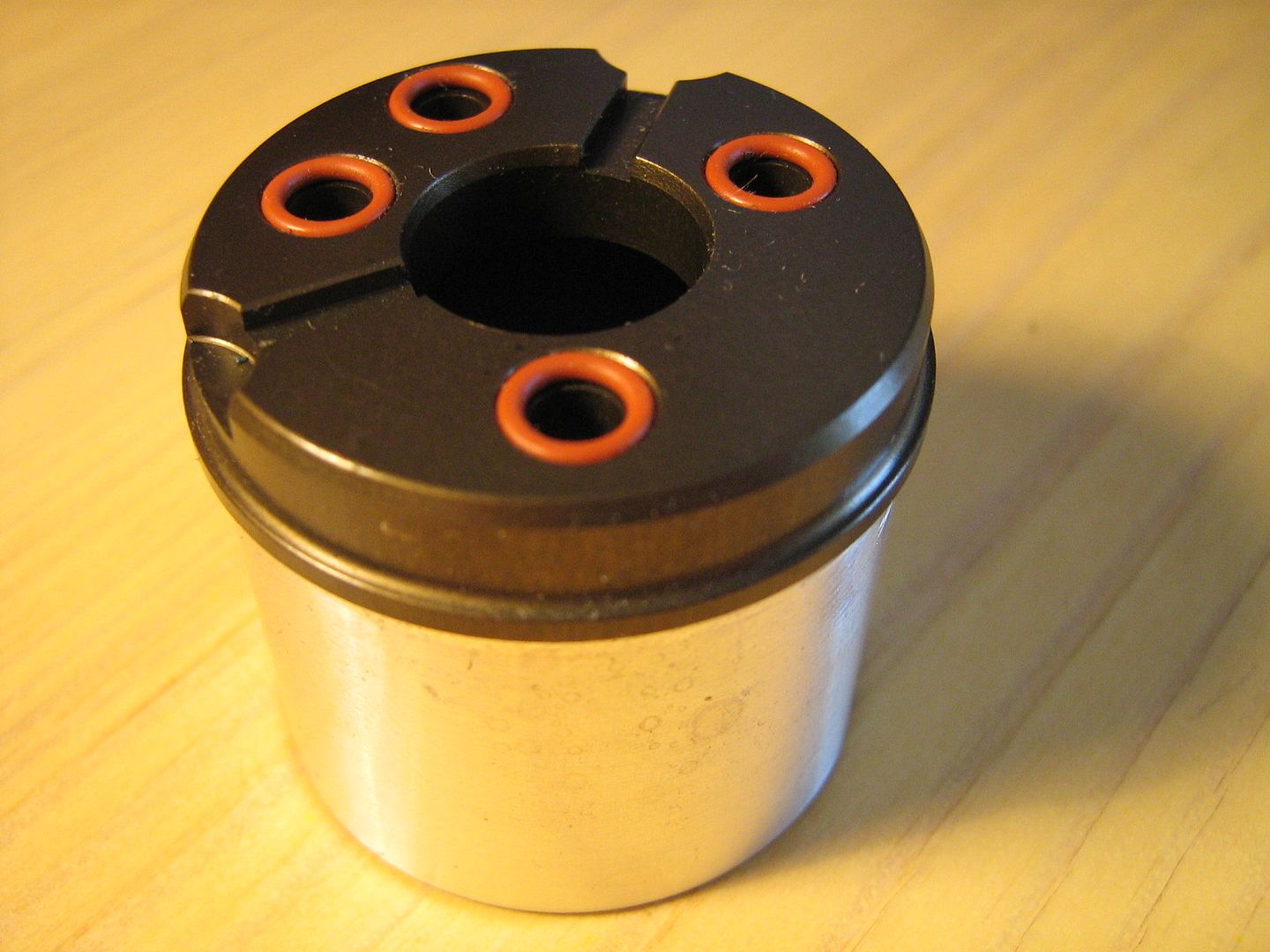
Notice too the orange seals (x4) required to seal the barrel to the counter-bore, three for the screws, one for the air hole,
Internally, the barrel base has been pocket milled out in order to lighten between the screw positions,
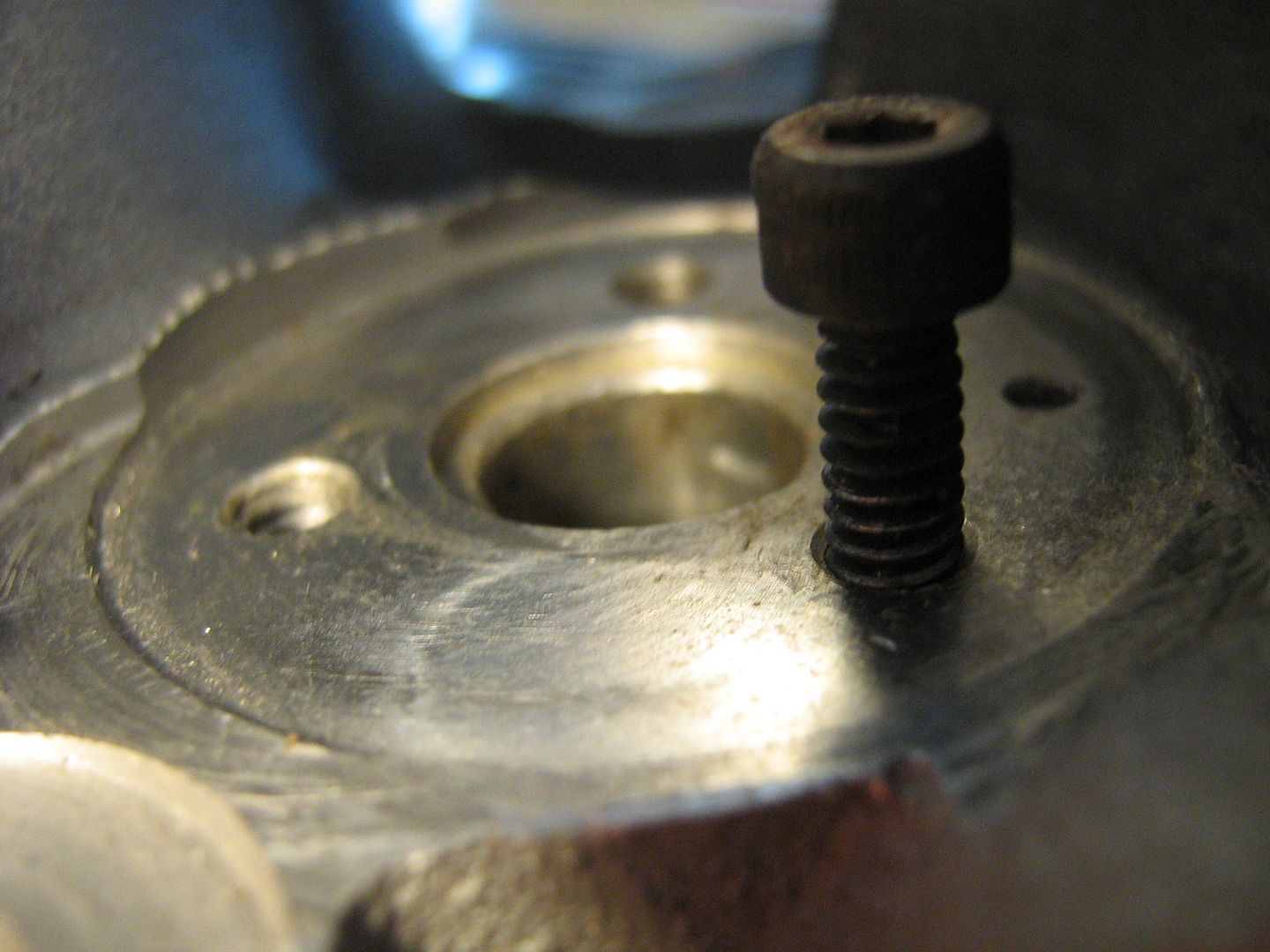
The screws do not lie equally (120 degrees)about the centre meaning the barrels cannot be installed/indexed wrong blocking off the air entry hole.
With the guide removed and installed in the barrel you can see how the grooves in the base feed the groove in the guide,
The hole in the bottom of the barrel is angled at the corners to allow the barrel to be installed down on the guide compressing the O ring as it is eased down therefore avoiding damage to seal and doing away with any special tools.
The tappets are pretty much 'standard items as far as it goes,
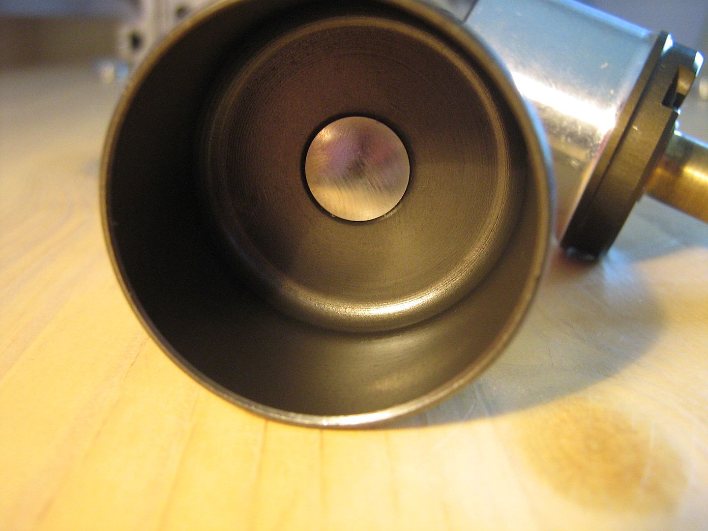
The body of the barrel is turned down to allow the tappet to slide down over it without crash when the valve is in the full open position,
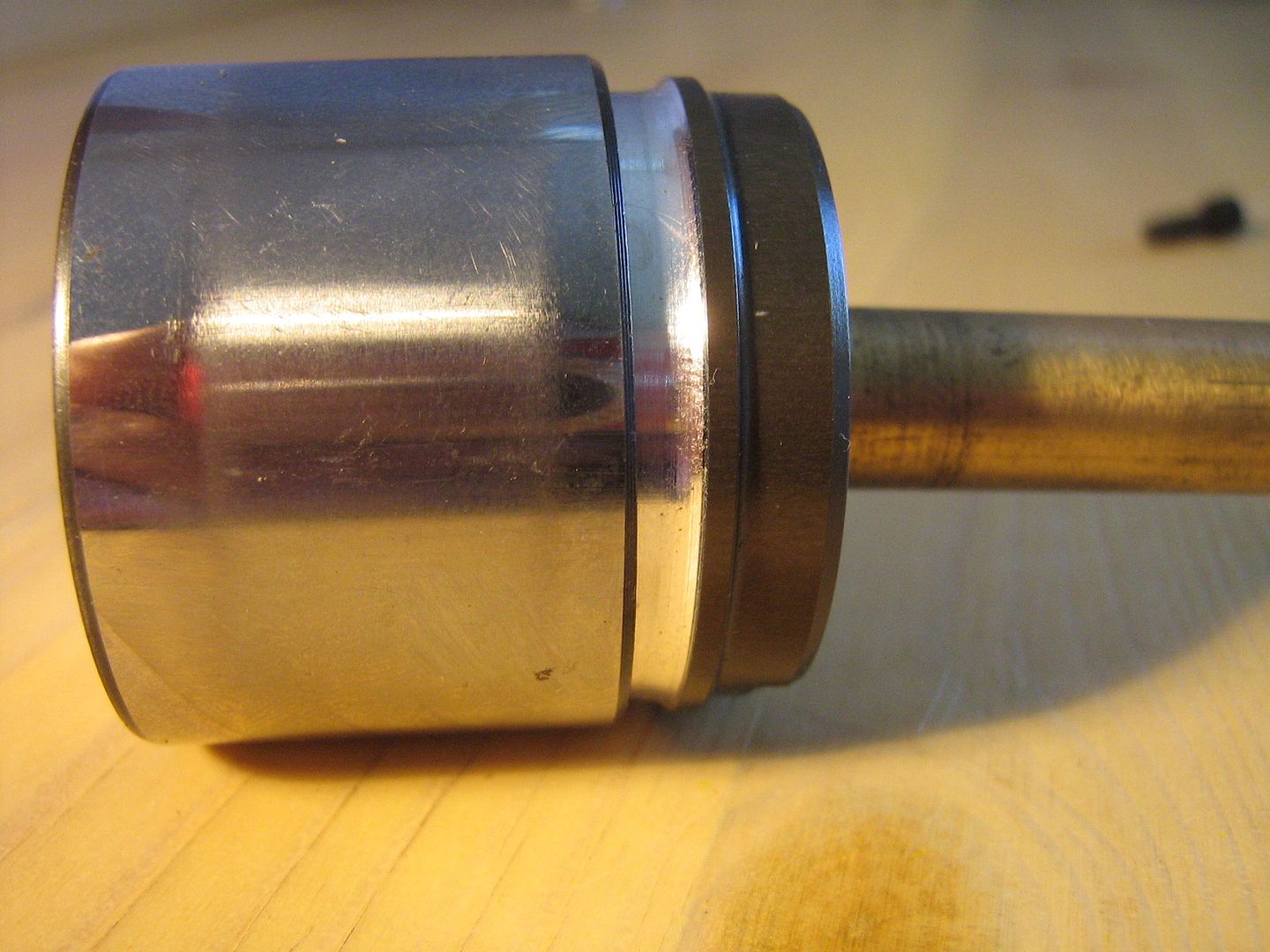
Here you can see just how little clearance there is between the tappet bore, and the barrel wall when installed - the tappet slides in this gap,
Installed, with the squirter aimed at the centre,
Here is a shot of the top of the valve guide seal, I took it before everything had been stripped and polished before the analysis started,
Here is the same valve guide with the seal removed and the entire thing media blasted and polished for easy insertion in and out of valve guide drilling to port,
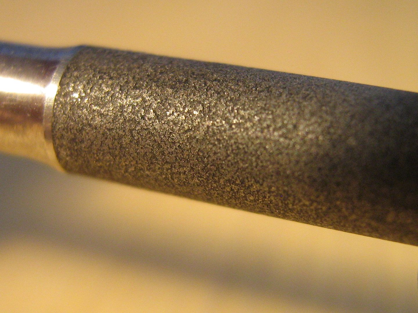
The stem of valve, complete with low friction texture surface coating for improved oil retention - remember, a hydrodynamic film is not easy sustain on a reciprocating valve stem and it is relying more-so on boundary lubrication. On close inspection it does look more like PVD coating but further testing required to be certain, the 'roughness' certainly does aid oil retention,
The assembly,
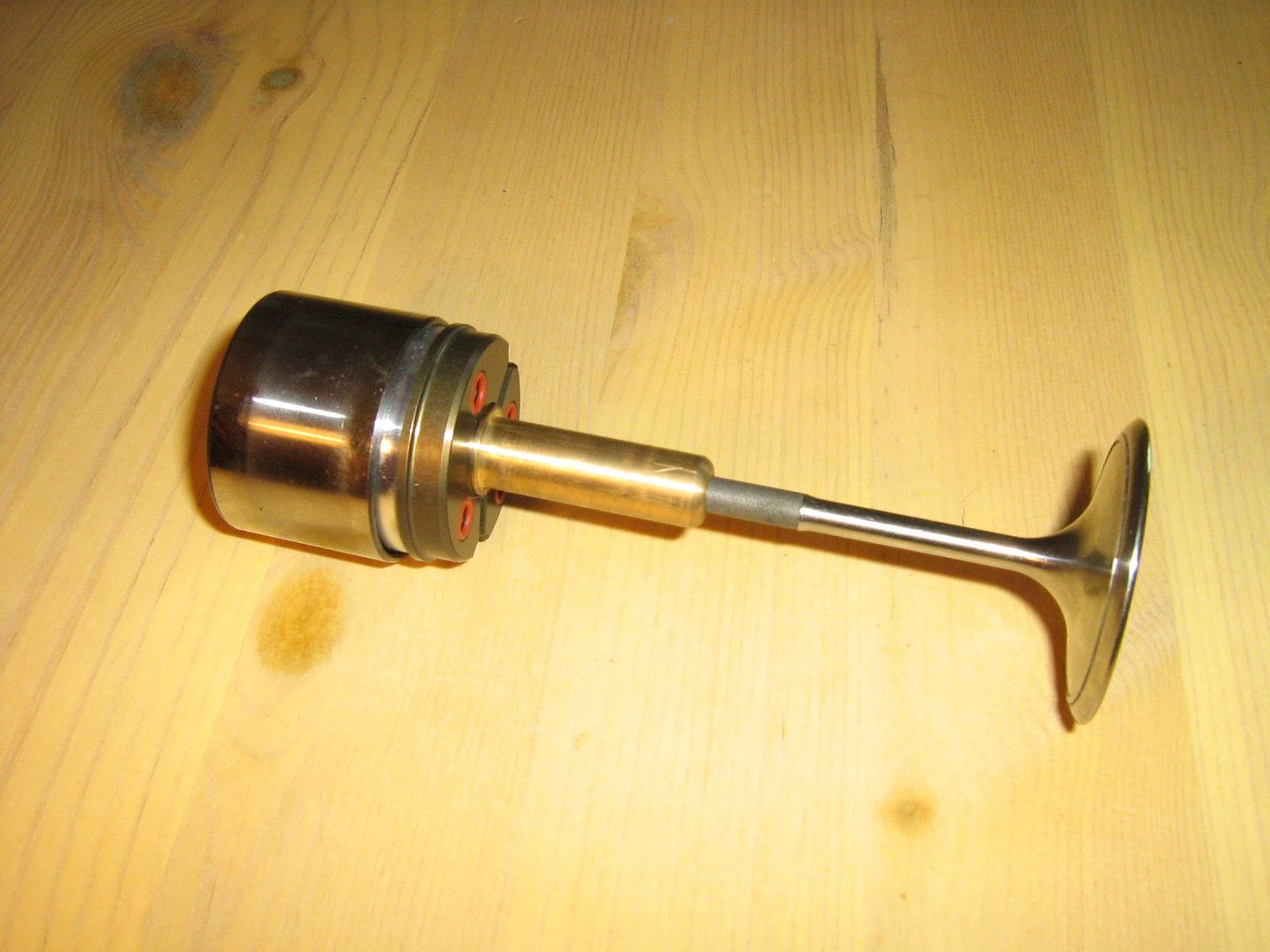
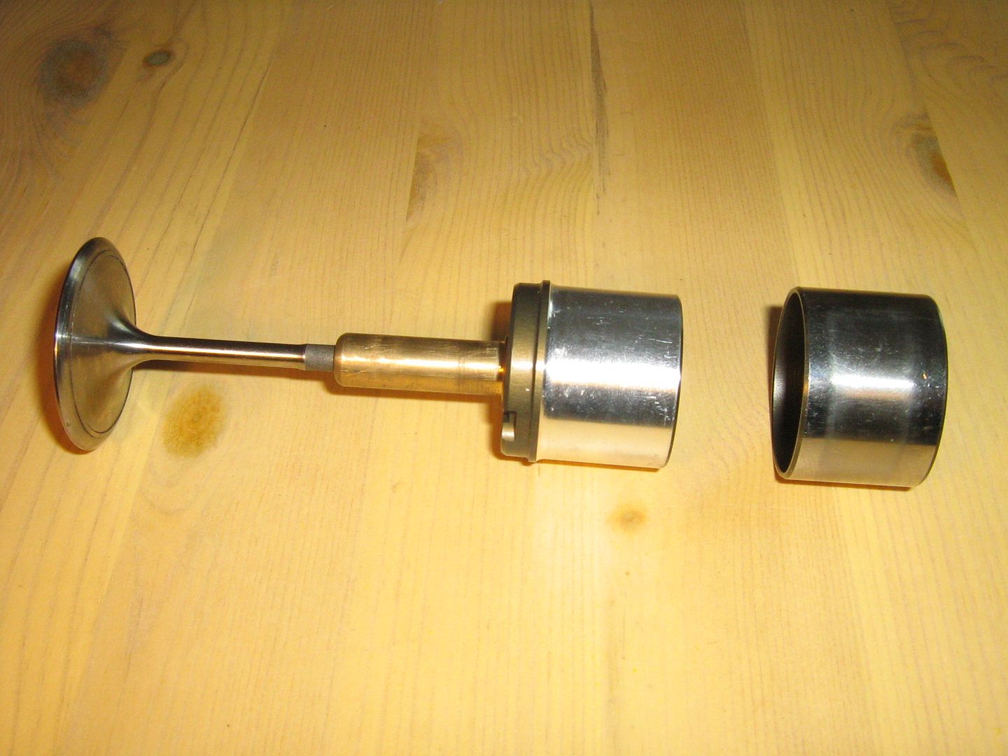
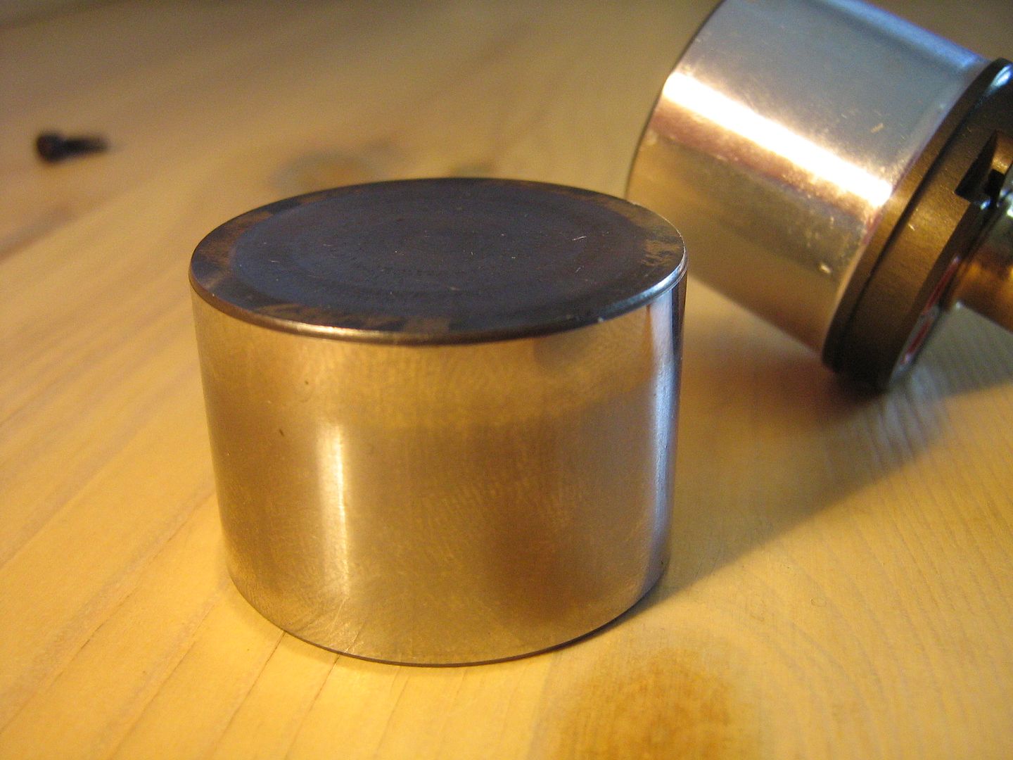
The barrel interior bore is of extremely high surface finish, almost mirror like. One of the most critical features with such dry sliding seal design we see here is surface finish on the bore walls. It must resist corrosion during periods while the engine is being built, being stored, or is in transit. The cylinder features hardcoat anodic coating internally and externally on the base. The anodic coating also benefits in terms of lessening sliding friction when impregnated with PTFE.
As mentioned at the start of this thread Im choosing not to show pictures of some of the pneumatic parts, in this case the piston. It is nothing special and has just two seals, one in the centre where stem passes through it, its located on the underside of the piston below the collets and is that same type seal we have seen above in the top of the guide except no sliding exists at this seal since the stem and piston/collet keeper are an item.
The other seal is located in the edge of the piston and is the main gas seal between the barrel and the piston. Again, it is nothing special and dare I say a 'common' seal/arrangement.
So in total there are eight seals needed in each pneumatic valve spring assembly - two of which are sliding seals, the other four being static o-ring seal arrangements. The first of the sliding seals is situated in the piston itself where it seals against cylinder bore, the second sliding seal resides in the top of the valve stem where it provides a seal with the valve stem. The other four seals are used around cylinder fixing holes, air feed hole, and valve stem hole through piston. This amounts to a total of eighty seals just in the pneumatic spring assemblies alone.
No air control valve/reg or valving items are present within the head itself.
Ill finish with two shots of the combustion chamber itself,
With all of the above in mind I hope the thread and information here has helped everyone from Casual Viewers, Enthusiasts, F1 fans, Engineers, Designers, Students, and Teachers Worldwide.
All pictures are backed up and on 20yr prepay hosting so they are not going to vanish anytime soon.
Regards,
Brian Garvey.
--------------------------------------------------------------
Now updated with more Info from Page 3. Im sticking it into the first post also for viewers on mobile devices and so on, 04/09/2013, BG
Just to provide another little bit of info with regards sand casting and general layout as it will save me answering a wall of emails that Ive getting daily about this thread, for which I want to say thanks again on all the kind words I have received from all over in such short time.
A complex sand mould is made up of a lot of parts. You will have all the parts to form the outside geometries on the part, from flanges, to faces, to brackets, to walls, and so on. You will then have more parts required to form the internal 'ways' inside the part. These range from liner bores, valleys, crank cases, cam boxes, water ways, and so on.
These are formed with sand parts called cores as mentioned in the original post.
In the case of a head or a block, the outer moulds are first built up, in these first moulds the runners to feed the part are also formed when making the sand moulds. Locations for filling the mould, a spot for the filter - to filter the incoming alloy, runners to feed the gates, and then the gates into the part itself.
As the main mould is being built up the cores are inserted and the main mould then closed off with more parts.
The last large top section on the mould will always have large storage areas at the top called risers to hold access metal.
The purpose of these large risers is to form head pressure on the metal within the moulds, to feed the part as it cools and shrinks, and to ensure good flow through the part so that no cold fronts stay in the finished casting.
A cold front is where two flows of alloy meet, the front edge of these flows can be a lower temperature than the rest of the metal and upon meeting form a poor bond. The purpose of the large risers is to rid the part of these cold front meet areas by effectively flushing the entire mould with non turbulent molten alloy so to speak.
The risers are often the same volume, or greater than the entire main casting.
The risers freeze of last and aid with directional solidification.
The gates always freeze off first, and the solidification travels up through the part, and ceases at the largest thermal mass, the risers.
Making the part uniform in thickness throughout is vital in correct directional solidification.
If a thick section exists within the part it will cool slower than the surrounding thin areas. This is very bad and results in tearing of the metal around the thick section, sometimes visible, other times not. The cause of this is due to the fact that the thick part takes longer to cool, and there will try and 'suck' metal from the thin areas as it shrinks. Since the thin sections are already cool, tearing will occur.
Another problem can crop up if you have to have a thick section within a part that you cannot do without. Such sections can be locations not yet bored for head blots, or bosses for valve guides. These high mass problematic areas can be altered in terms of temperature by using something called chills to combat tear problems.
Ill post a few of my own images taken in Maranello for further description of terms. A picture paints a thousand words so they say.
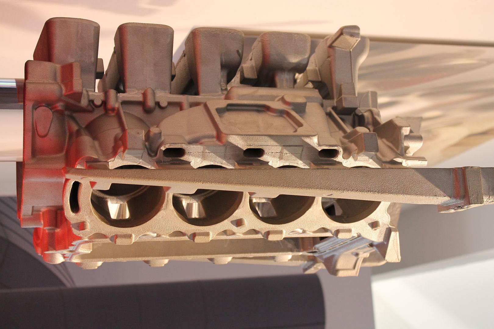
Below you can see a block casting left on its end,
Turned as it would be when poured you can see several of the items mentioned above, in this image the main tapered runner feeding all the gates,
The sprue and filter system where the mould has been filled,
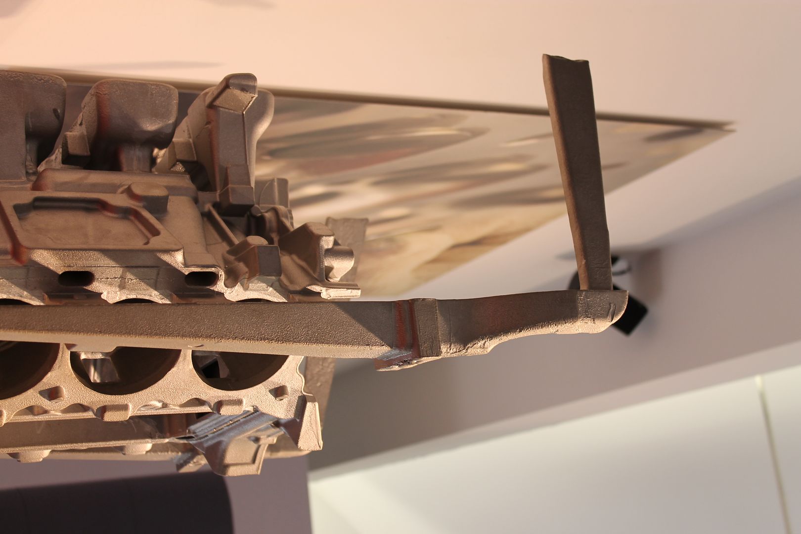
A shot from the other side better showing gates along block face, and also the large riser(s) mass,
A end shot showing riser height - all above the crank centre line is machined off, having it form the full way about the crank mains keeps the block more stable when pouring,
The gates, these are sized accordingly along the length of the block,
A shot of another block, showing both filters in the runner section, and also the imprints left by the chills as described above at the head bolt locations where the mass is greater. These can be cast iron, or sometimes a higher heat conducting metal. They are built into the sand mould and absorb a certain amount of extra heat from the surround location - keeping directional solidification in check,
More large risers,
This one uses a deep skirt runner, this type of runner can help even out the turbulence in the molten metal before it enters the gates. If you can imagine it just overflowing in the gates, rather than shooting in them - this is sort of the effect,
The gates, and chill prints,
An end view of a raw head casting - same story here as with the blocks, ample riser volumes too,
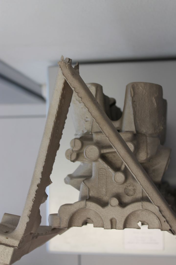
On its end, showing filter locations in runner,
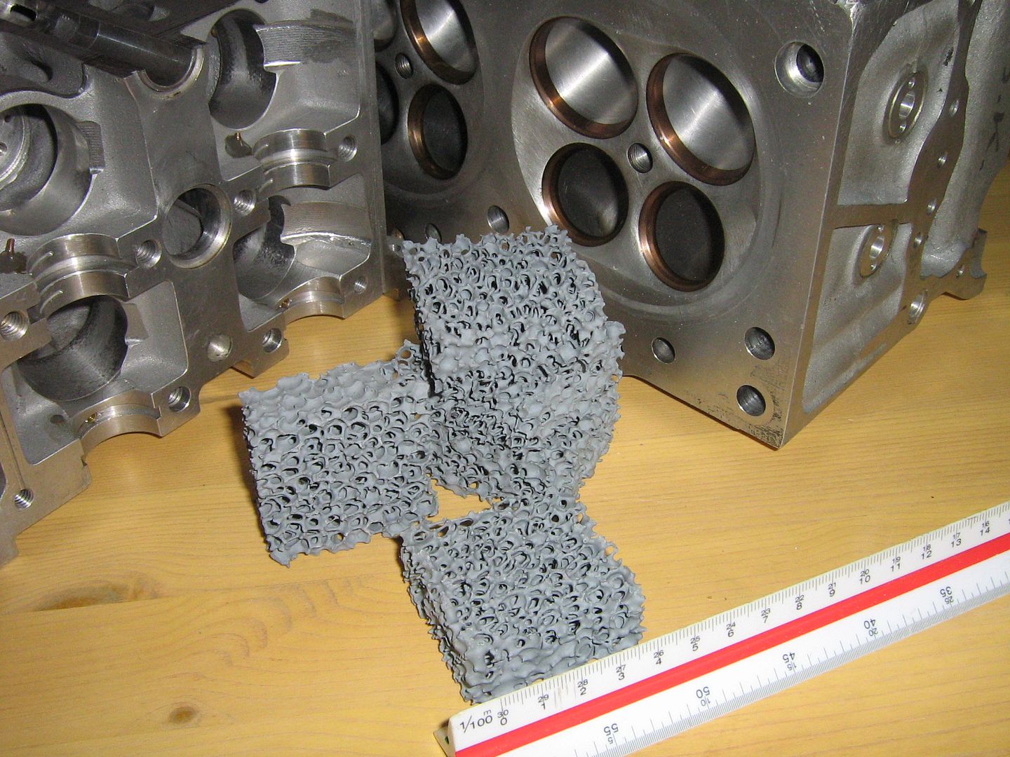
An example of the inline filters - these trap any dross in the metal, they are a ceramic foam,
Hopefully that will answer some more questions,
For a summary please view the video below, 1.30- 2.04 sums up the above a little better in visual terms,
http://www.youtube.com/watch?v=AdcoVurVY30
Brian Garvey.
+++++++++++++++++More info now added from Page 4++++++++++++++++++
Just to start adding the info before it piles up.
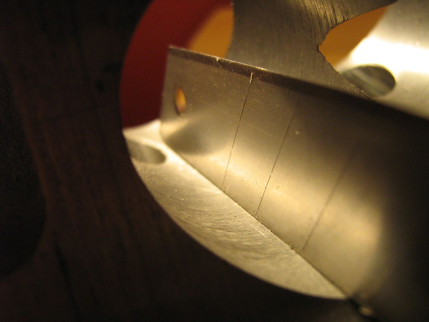
First, the seats
An overview,
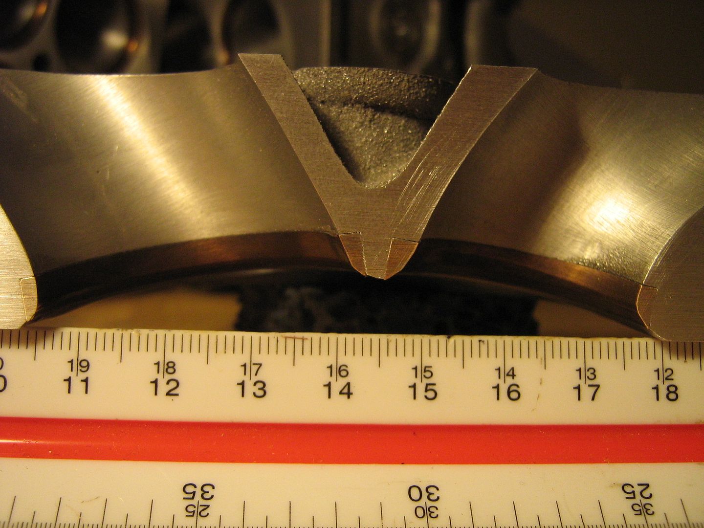
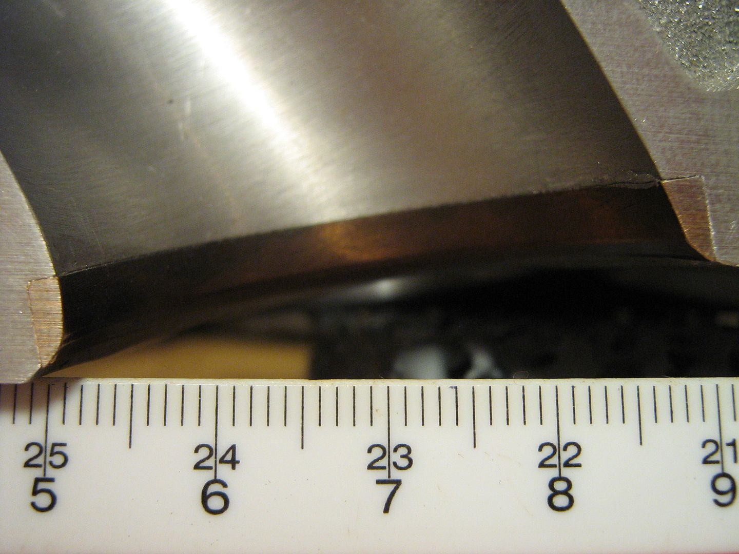
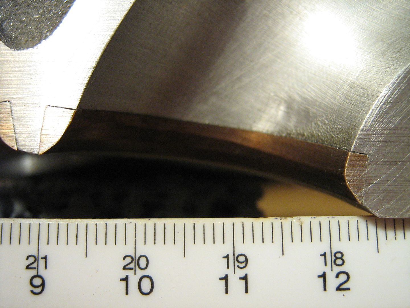
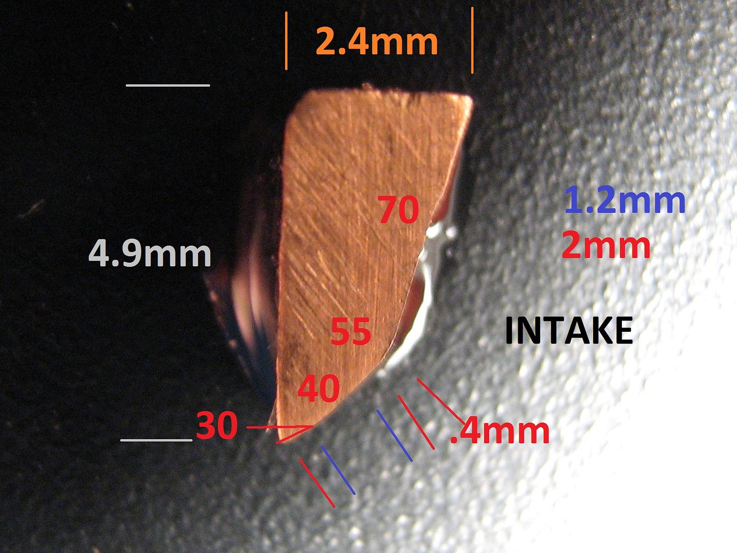
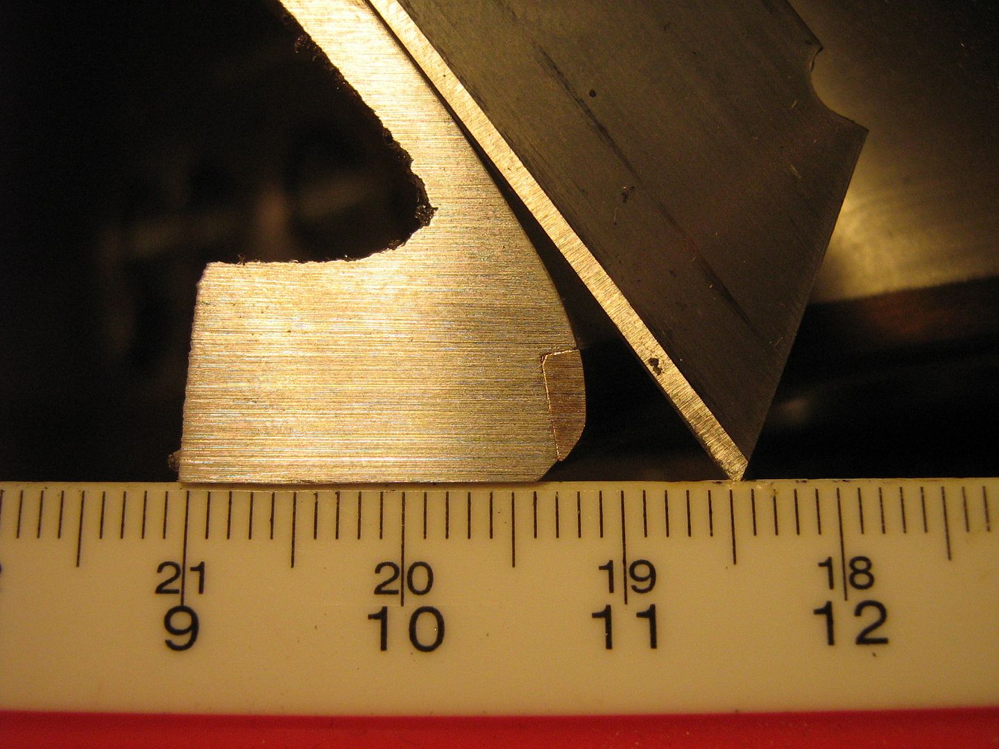
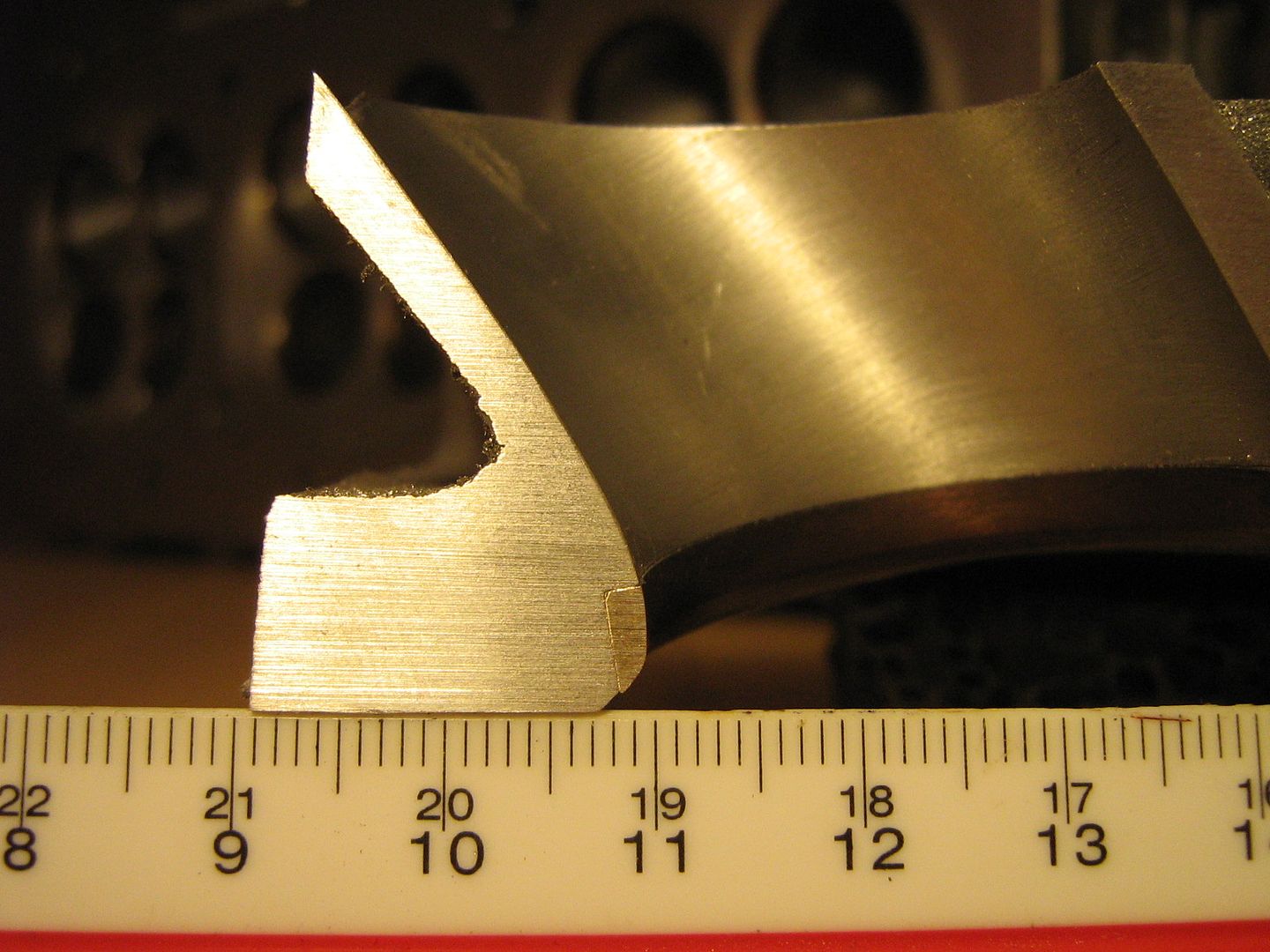
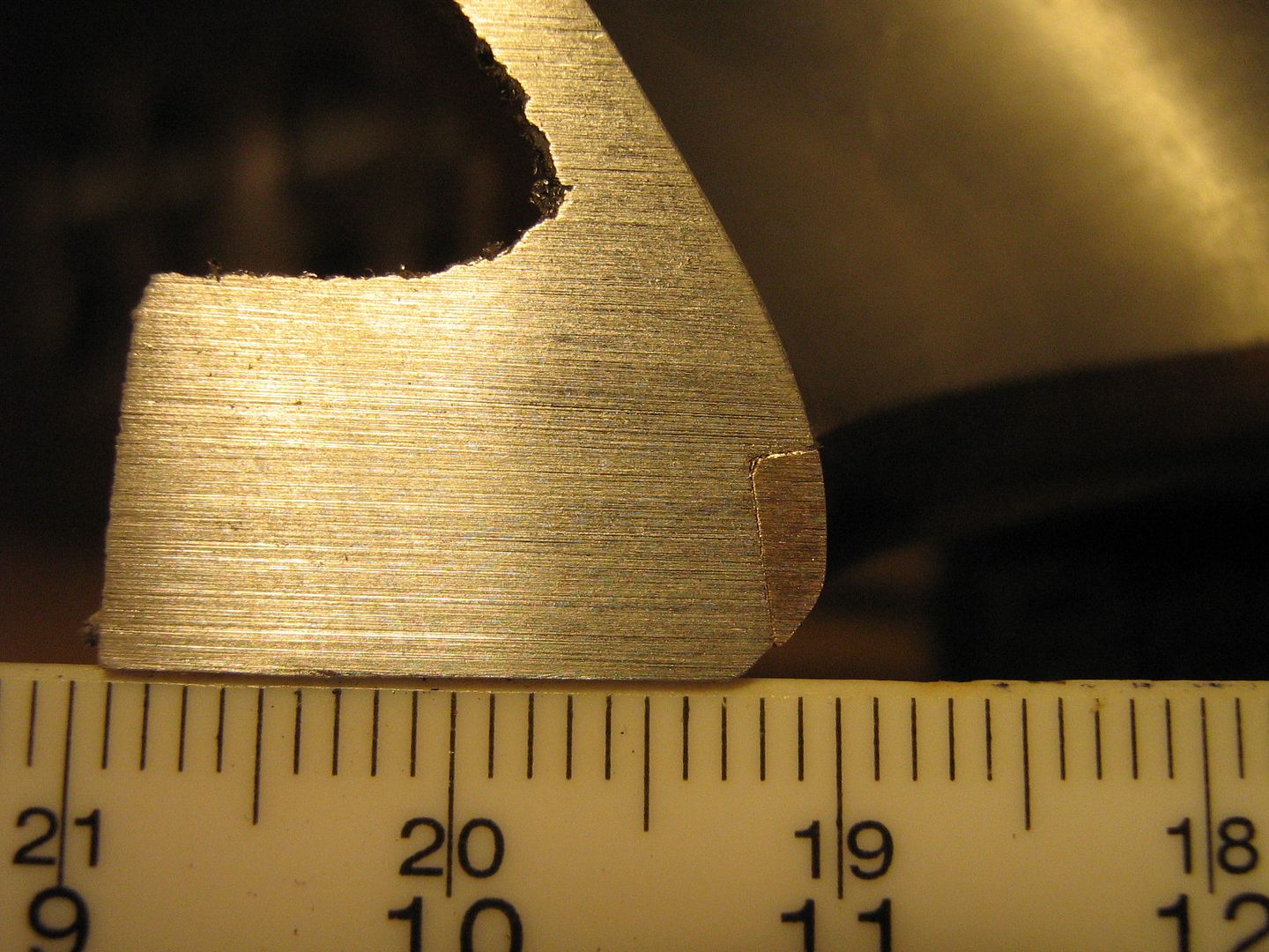
The intake port sides are straight for most of the way. The floor is straight until indicated below with the blade in the SSR shot,
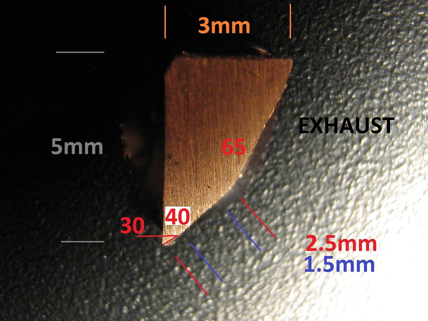
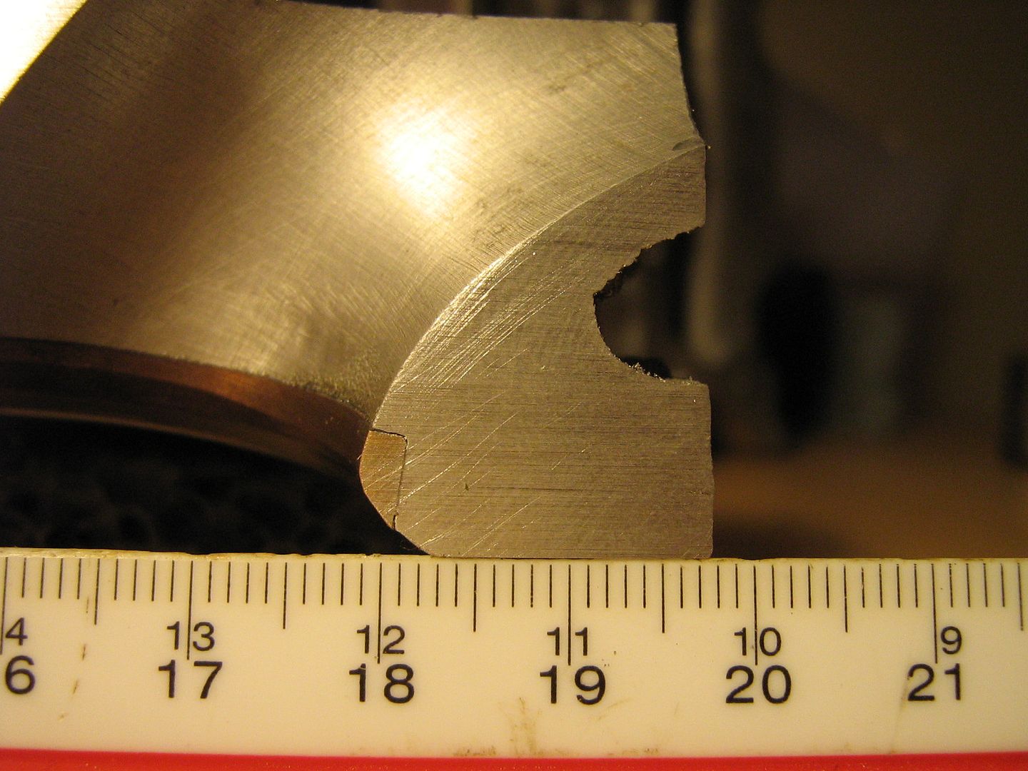
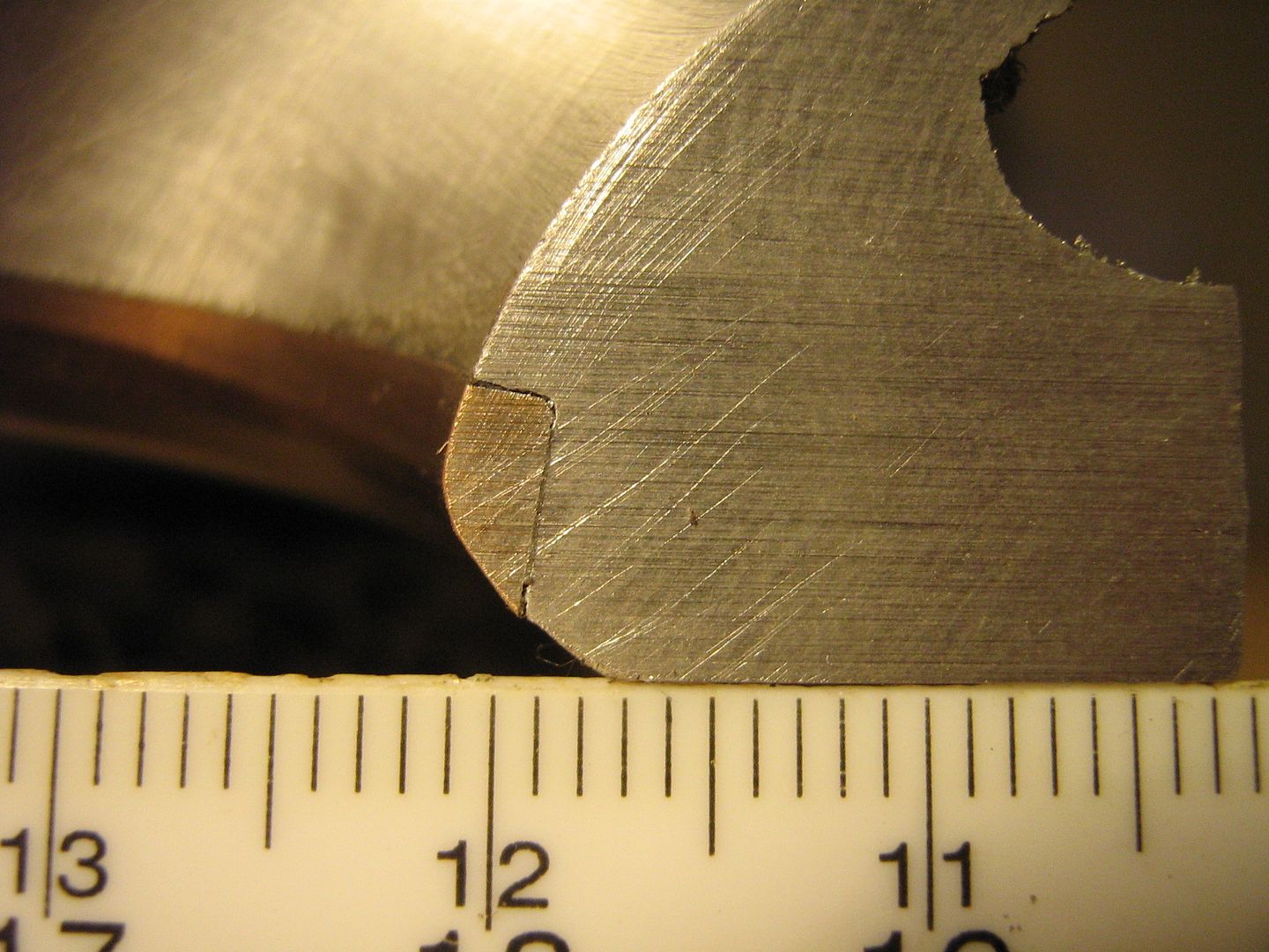
Close-ups of the various details - use ruler for sizing - It will give the opportunity to take real dimensions from any location without having to list,
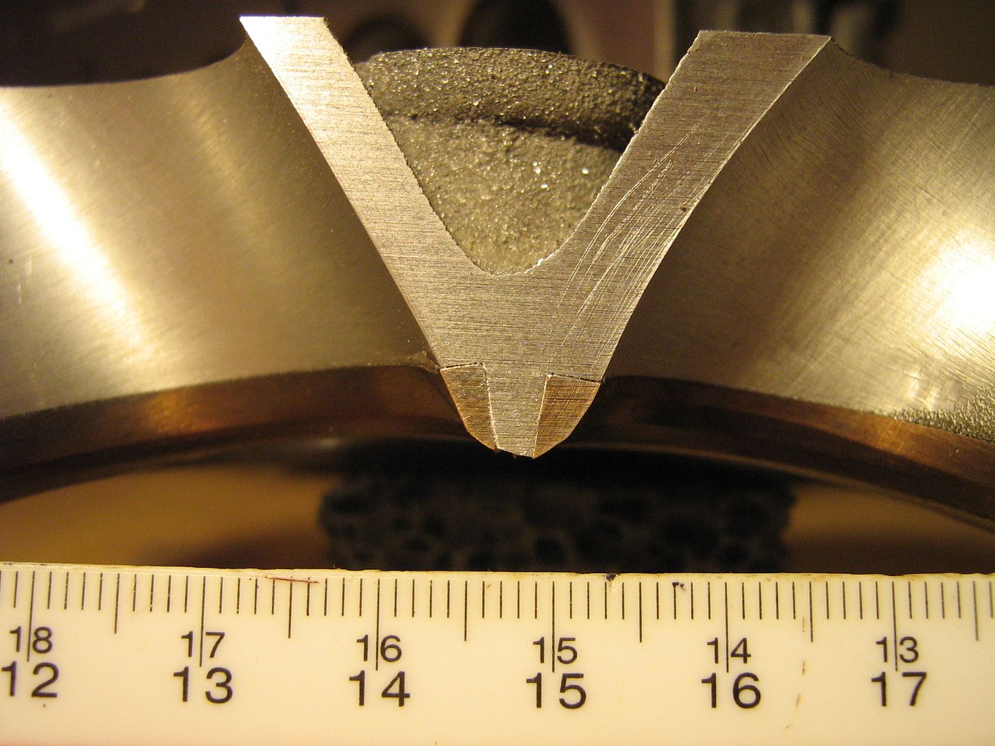
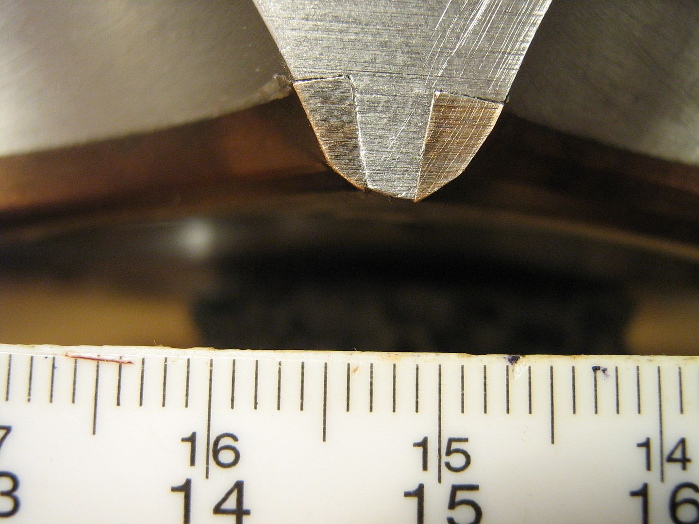
Lots more to add yet including cross-sections, volume, angles and valve sizes but its on the way.
Ive made up my mind also to perform some other flow tests as well as flowbench tests using either particle image velocimetry, or ink trace - In both cases a clear casting is made of the port/chamber and you can then view the flow/turbulence within it.
Ill get the hard measures mentioned above out of the way first. These should give good insight - the rest Ill share in 3d form once I get the silicone scanned.
More very soon,
Brian,