F1 Cylinder Head Design and Pneumatics, a closer look

All that has to do with the power train, gearbox, clutch, fuels and lubricants, etc. Generally the mechanical side of Formula One.
Brian.G
334
Joined: 10 Dec 2010, 23:52
Location: Ireland
Contact:

Re: F1 Cylinder Head Design and Pneumatics, a closer look

Post

Yes, sand casting.

A lot of performance heads in low volume are still cast this way - I can confirm that by saying that I inspected nearly all the F1 engines/heads in Maranello not too long ago. All castings I inspected also showed signs of wide parting lines, and mould draft, something not associated with investment methods.

Maybe the really newer ones are investment cast using the foam process as founded by GM but I cant be sure. The 'aeroboard' surface finish would be the give away, or else a milled like surface that would have transferred from the wax model - if they used wax.

I cant agree with the statement - 'sand cast being the reason they would need binning after a race' is true.

Lets not forget many road going Ferrari blocks and Heads still use the sand method.

Sand casting takes many forms - to manhole covers as mentioned in green water bond sand, to oil bond petro bond sand, to the higher grade resin bonded sand with post cure mould coatings of zircon/graphite talc wash.

I would guess now if using sand casting it is done through the 3d laser bonded sand process, where entire sand forms are made on a 3 axis laser machine, the laser curing the resin between sand particles to form whatever shape needed. This does away with any patterns, or coreboxes required when doing it the old way. This 3d printing can also me called digital sand moulding.

If they were to investment cast, tooling to make the moulds for either the wax, or expanded polystyrene would be needed, and you are talking alot more time from every aspect, but maybe....

http://www.mahle-powertrain.com/MAHLE_P ... ng-Process

Brian,
If you think you cant, you wont, If you think you can, you will

johnny99
1
Joined: 09 Apr 2009, 19:28
Location: Killucan Westmeath Ireland

Re: F1 Cylinder Head Design and Pneumatics, a closer look

Post

Cosworth used a pressure cast process, but I think it was implemented some time after Brian's head was made. I don't know much about the process, as I worked out of Northampton and Wellingborough. I do know however the alloy was pretty secretive and impossible to de-burr by machine, and were done by hand.

John

Brian.G
334
Joined: 10 Dec 2010, 23:52
Location: Ireland
Contact:

Re: F1 Cylinder Head Design and Pneumatics, a closer look

Post

johnny99 wrote:Cosworth used a pressure cast process, but I think it was implemented some time after Brian's head was made. I don't know much about the process, as I worked out of Northampton and Wellingborough. I do know however the alloy was pretty secretive and impossible to de-burr by machine, and were done by hand.

John
John, they did surely, it was pressurized into a zircon coated steel tool. This was mainly for mass production though, allowing faster cycle times and therefore reduced porosity due to upped pressures.
This then saved having to make new sand moulds for each shot, just spray tool with wash when open and away you go. Temperature can be also controlled locally via coolant channels, providing chilled areas to thicker sections.
Sand cores for coolant galleries still need manual placement within tool though as with current mass produced cylinder heads.

Brian,
If you think you cant, you wont, If you think you can, you will

xpensive
214
Joined: 22 Nov 2008, 18:06
Location: Somewhere in Scandinavia

Re: F1 Cylinder Head Design and Pneumatics, a closer look

Post

I cannot believe the valve-cover and front face are sand-cast surfaces, neither machined?

http://www.google.com/search?q=renault+ ... 680%3B1095
"I spent most of my money on wine and women...I wasted the rest"

Brian.G
334
Joined: 10 Dec 2010, 23:52
Location: Ireland
Contact:

Re: F1 Cylinder Head Design and Pneumatics, a closer look

Post

xpensive wrote:I cannot believe the valve-cover and front face are sand-cast surfaces, neither machined?

http://www.google.com/search?q=renault+ ... 680%3B1095
Its hard to tell on the gear cover, it looks like a billet machine item, but the cam cover is defiantly sand cast yes.
Dont forget if its surface finish you are looking at, the finish will be the same texture/roughness as body primer on a car since the zircon coating is sprayed onto the sand moulds with a spray gun in most cases, and not brushed on. This gives a very fine finish to the poured part.

Below is an example of part of an intake manifold mould Im making for one of my own projects, here the sand is very fine resin bond, and even before spraying with the zircon/graphite talc the surface finish is extremely smooth.

Image

The zircon/graphite talc is very fine powder suspended in iso-alcohol and once it is sprayed on, it is then flame dried to flash off the alcohol leaving a super smooth surface, which translates to a smooth metal finish then also,

Brian,
If you think you cant, you wont, If you think you can, you will

Brian.G
334
Joined: 10 Dec 2010, 23:52
Location: Ireland
Contact:

Re: F1 Cylinder Head Design and Pneumatics, a closer look

Post

Just to provide another little bit of info with regards sand casting and general layout as it will save me answering a wall of emails that Ive getting daily about this thread, for which I want to say thanks again on all the kind words I have received from all over in such short time.

A complex sand mould is made up of a lot of parts. You will have all the parts to form the outside geometries on the part, from flanges, to faces, to brackets, to walls, and so on. You will then have more parts required to form the internal 'ways' inside the part. These range from liner bores, valleys, crank cases, cam boxes, water ways, and so on.
These are formed with sand parts called cores as mentioned in the original post.

In the case of a head or a block, the outer moulds are first built up, in these first moulds the runners to feed the part are also formed when making the sand moulds. Locations for filling the mould, a spot for the filter - to filter the incoming alloy, runners to feed the gates, and then the gates into the part itself.

As the main mould is being built up the cores are inserted and the main mould then closed off with more parts.
The last large top section on the mould will always have large storage areas at the top called risers to hold access metal.
The purpose of these large risers is to form head pressure on the metal within the moulds, to feed the part as it cools and shrinks, and to ensure good flow through the part so that no cold fronts stay in the finished casting.

A cold front is where two flows of alloy meet, the front edge of these flows can be a lower temperature than the rest of the metal and upon meeting form a poor bond. The purpose of the large risers is to rid the part of these cold front meet areas by effectively flushing the entire mould with non turbulent molten alloy so to speak.
The risers are often the same volume, or greater than the entire main casting.
The risers freeze of last and aid with directional solidification.
The gates always freeze off first, and the solidification travels up through the part, and ceases at the largest thermal mass, the risers.
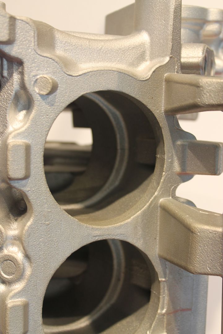
Making the part uniform in thickness throughout is vital in correct directional solidification.
If a thick section exists within the part it will cool slower than the surrounding thin areas. This is very bad and results in tearing of the metal around the thick section, sometimes visible, other times not. The cause of this is due to the fact that the thick part takes longer to cool, and there will try and 'suck' metal from the thin areas as it shrinks. Since the thin sections are already cool, tearing will occur.

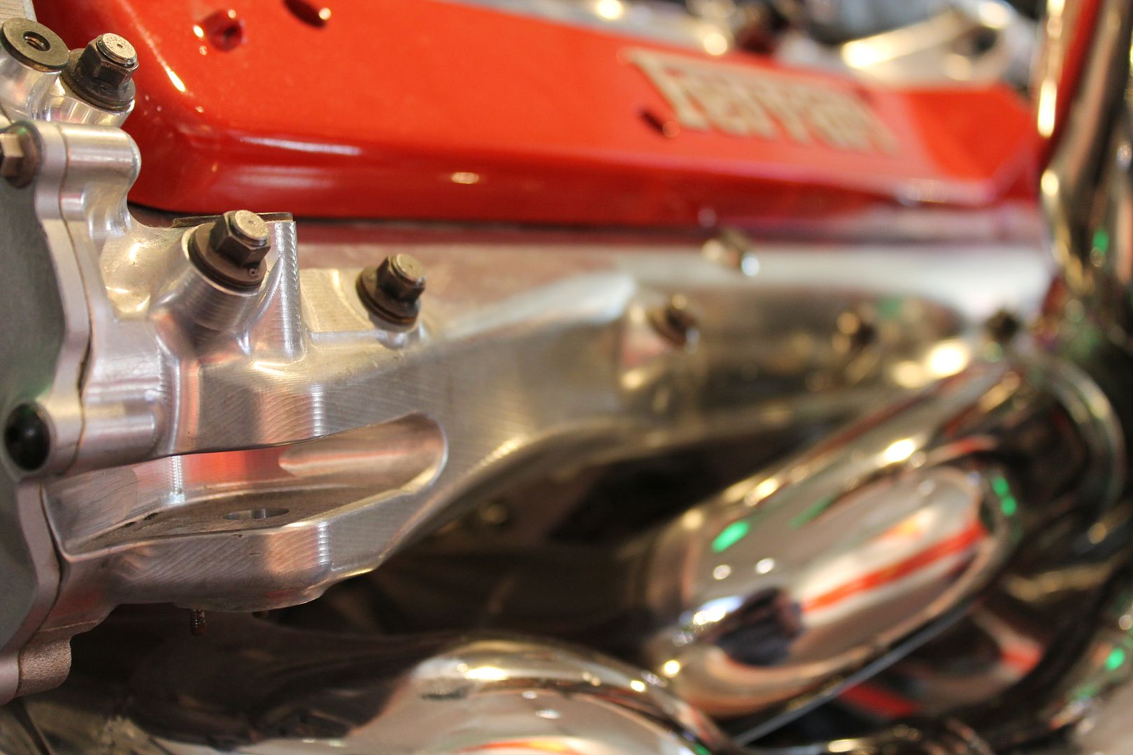
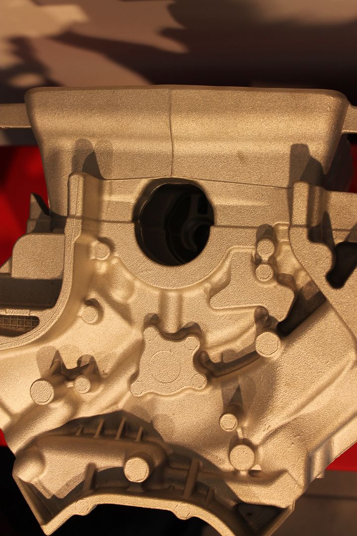
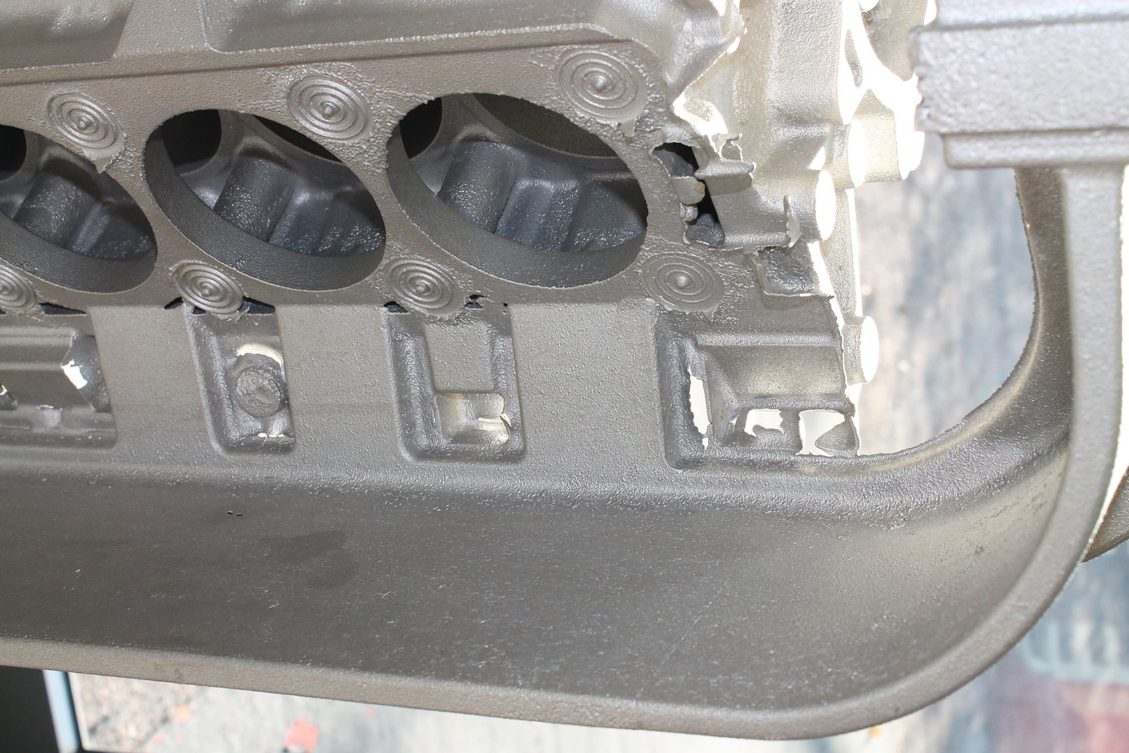
Another problem can crop up if you have to have a thick section within a part that you cannot do without. Such sections can be locations not yet bored for head blots, or bosses for valve guides. These high mass problematic areas can be altered in terms of temperature by using something called chills to combat tear problems.

Ill post a few of my own images taken in Maranello for further description of terms. A picture paints a thousand words so they say.

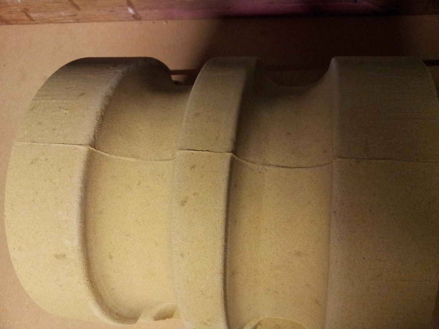
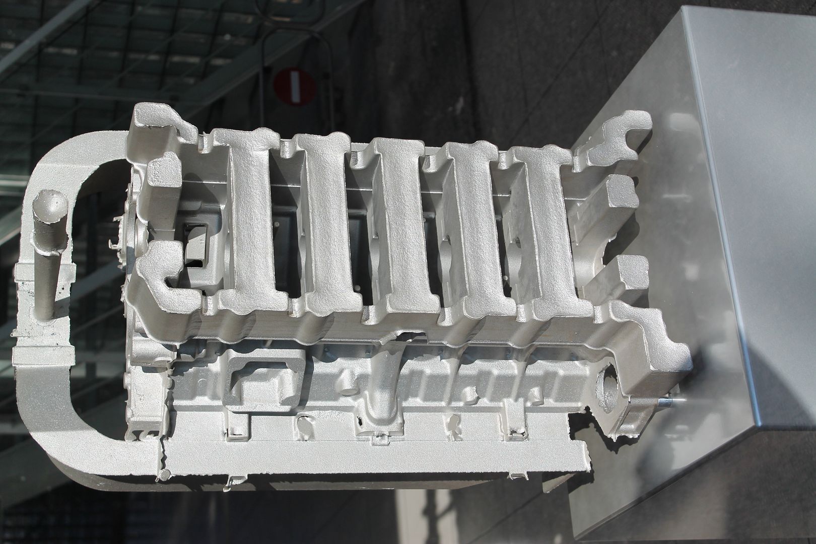
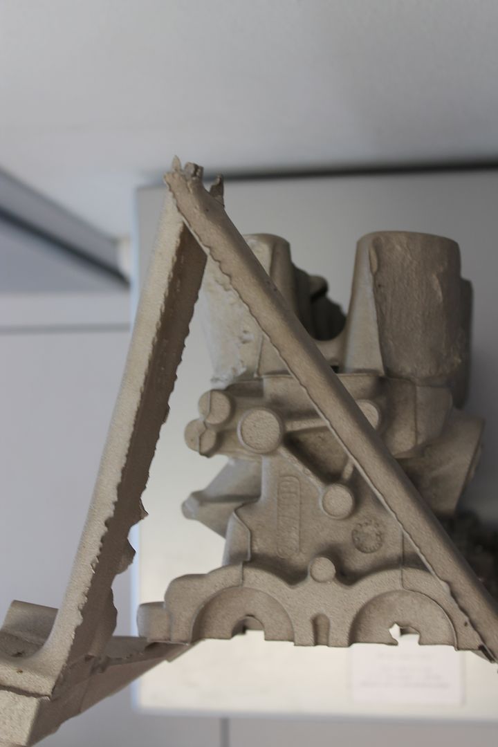
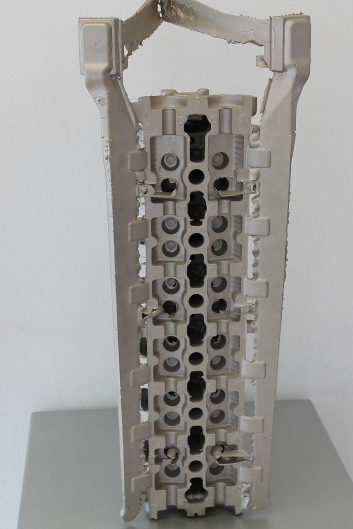
Below you can see a block casting left on its end,

Image

Turned as it would be when poured you can see several of the items mentioned above, in this image the main tapered runner feeding all the gates,

Image

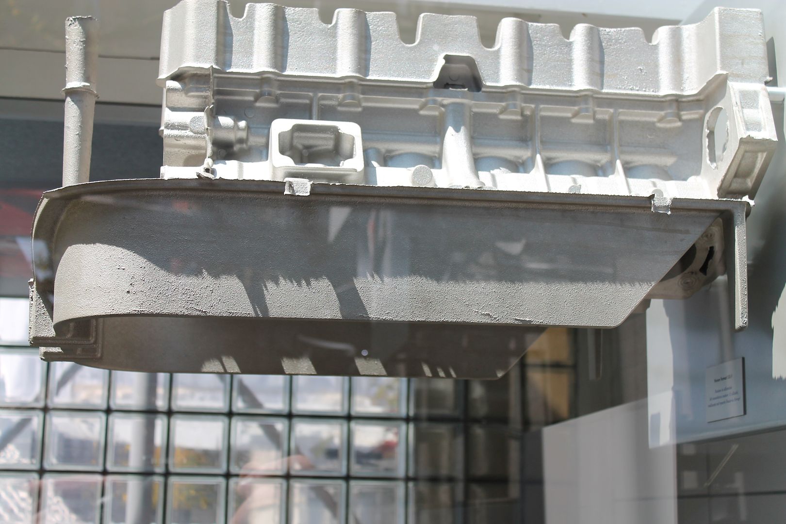
The sprue and filter system where the mould has been filled,

Image

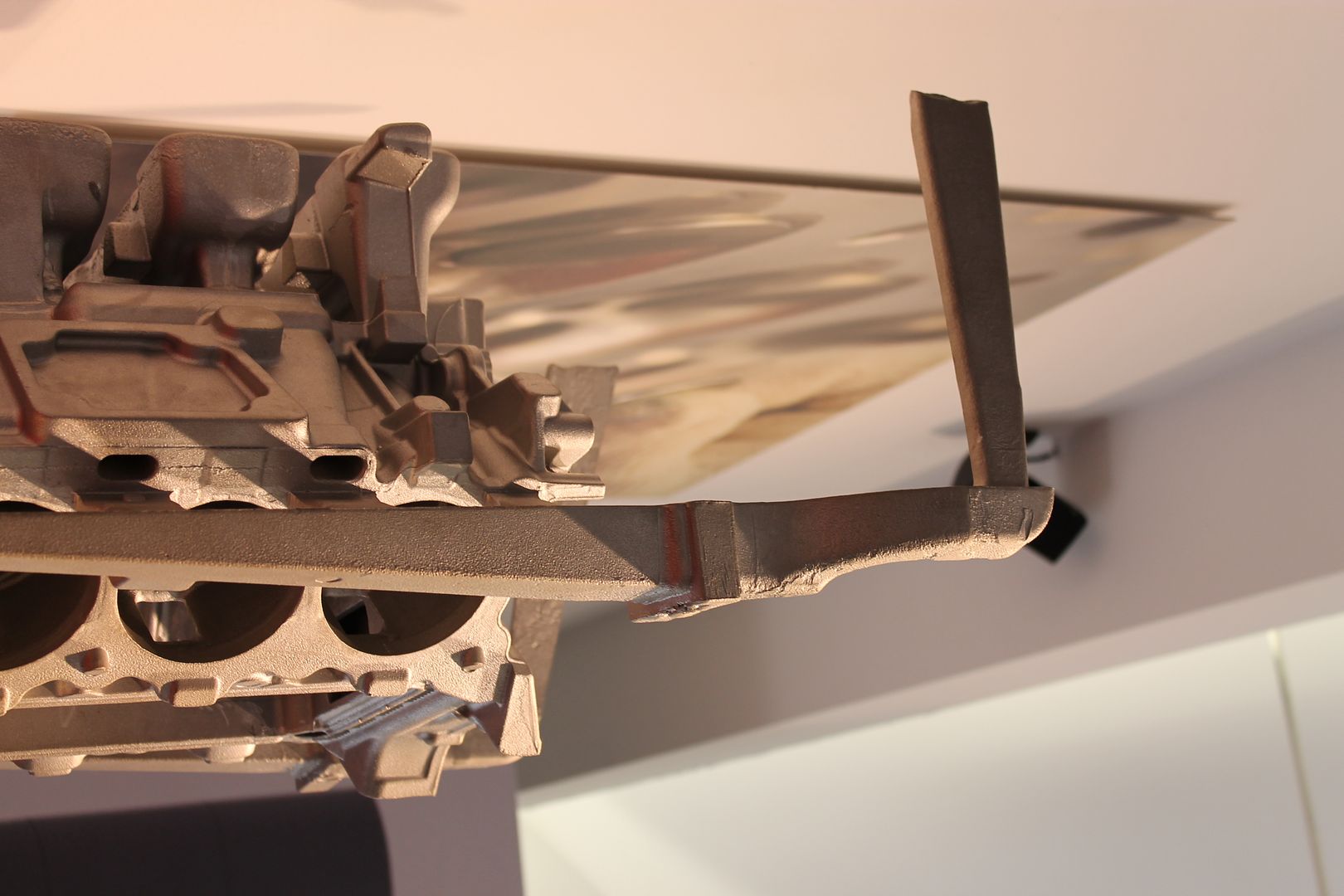
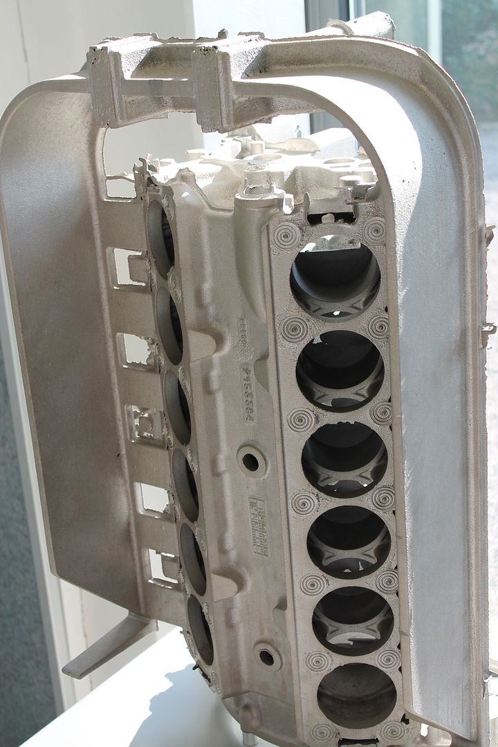
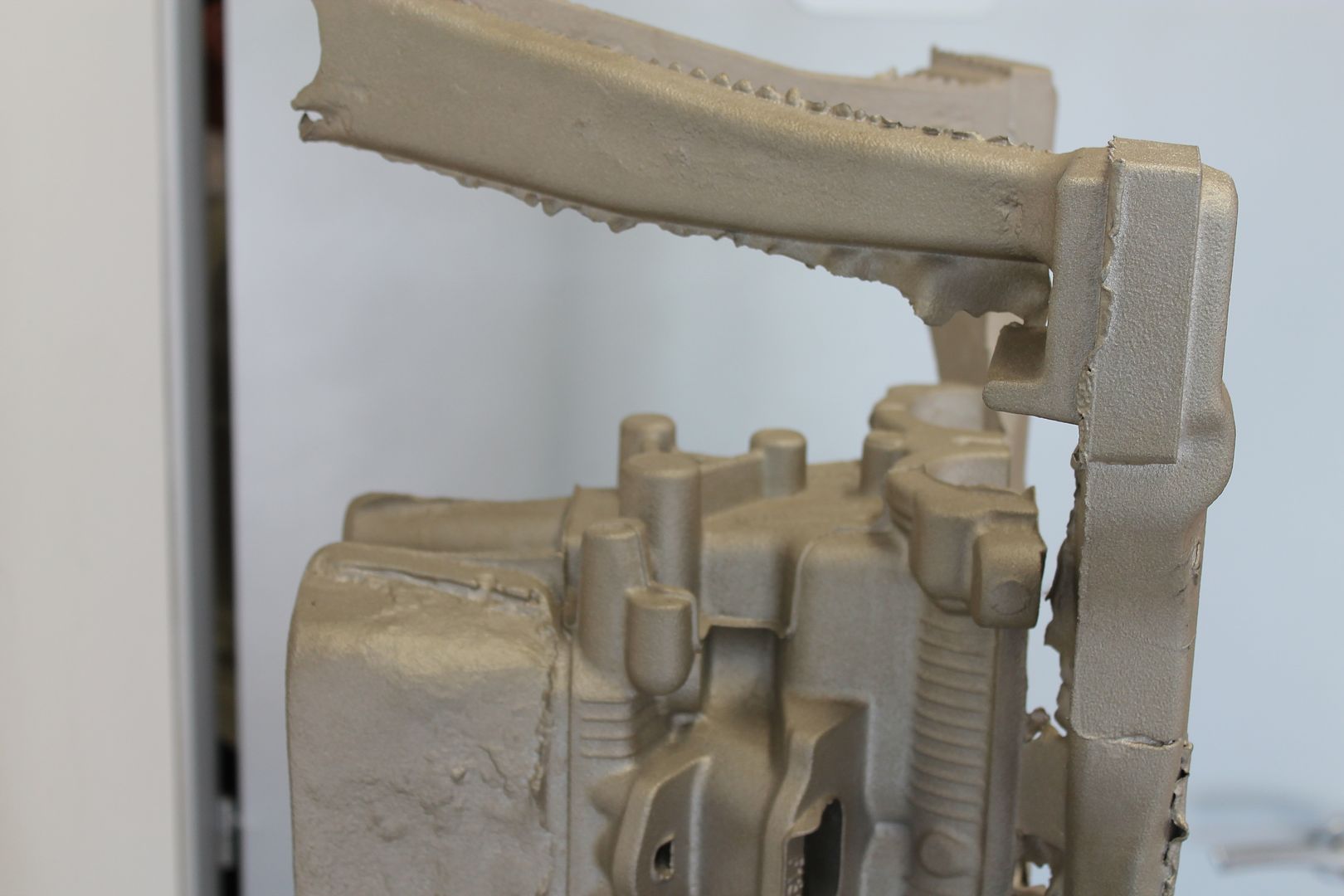
A shot from the other side better showing gates along block face, and also the large riser(s) mass,

Image

A end shot showing riser height - all above the crank centre line is machined off, having it form the full way about the crank mains keeps the block more stable when pouring,

Image

The gates, these are sized accordingly along the length of the block,

Image

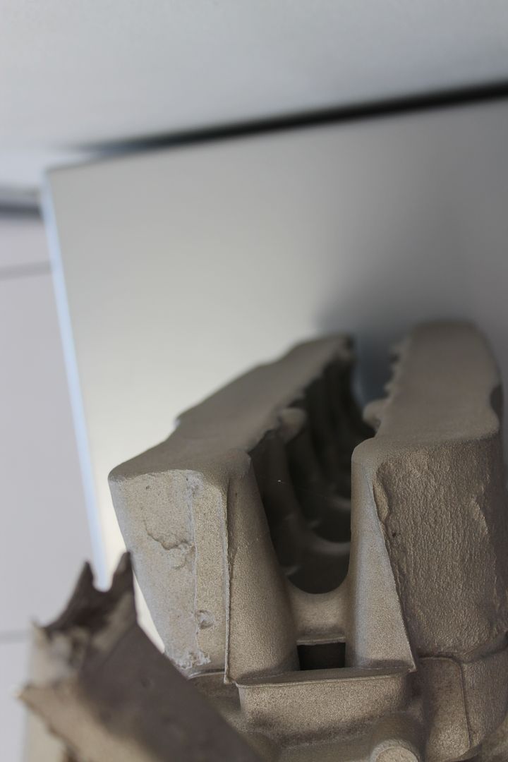
A shot of another block, showing both filters in the runner section, and also the imprints left by the chills as described above at the head bolt locations where the mass is greater. These can be cast iron, or sometimes a higher heat conducting metal. They are built into the sand mould and absorb a certain amount of extra heat from the surround location - keeping directional solidification in check,

Image

More large risers,

Image

This one uses a deep skirt runner, this type of runner can help even out the turbulence in the molten metal before it enters the gates. If you can imagine it just overflowing in the gates, rather than shooting in them - this is sort of the effect,

Image

The gates, and chill prints,

Image

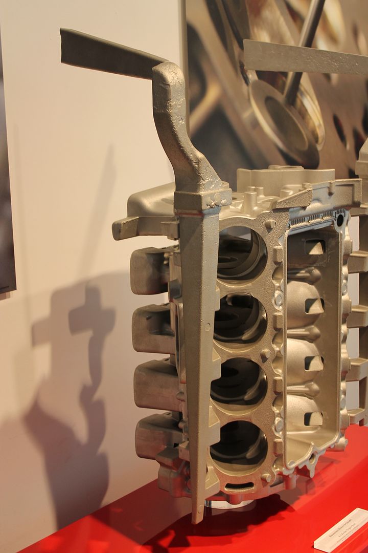
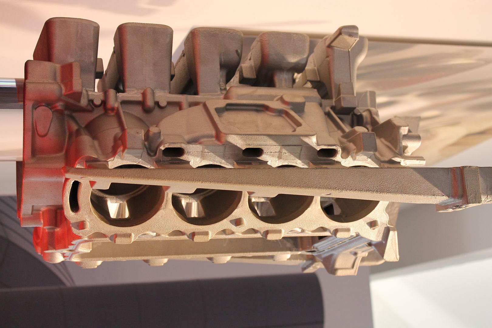
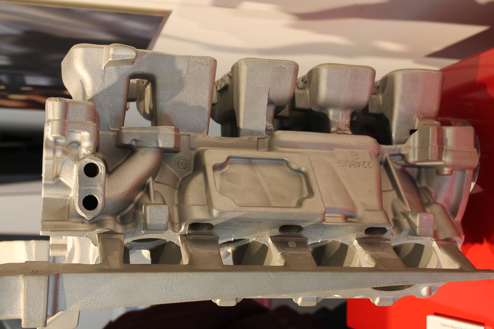
An end view of a raw head casting - same story here as with the blocks, ample riser volumes too,

Image

Image

On its end, showing filter locations in runner,

Image

Image

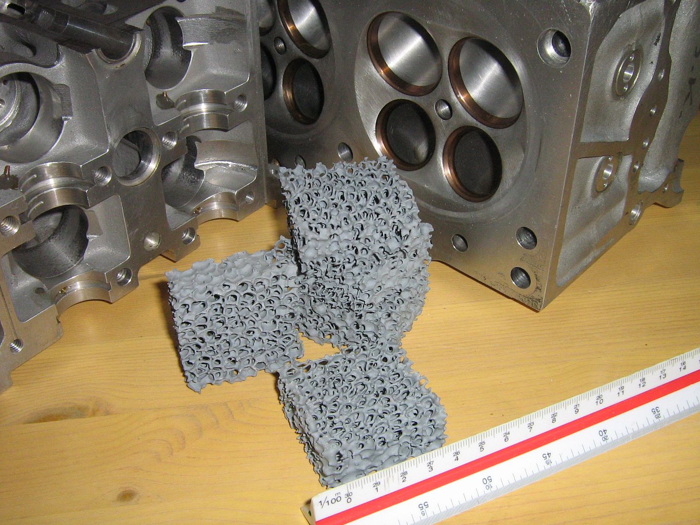
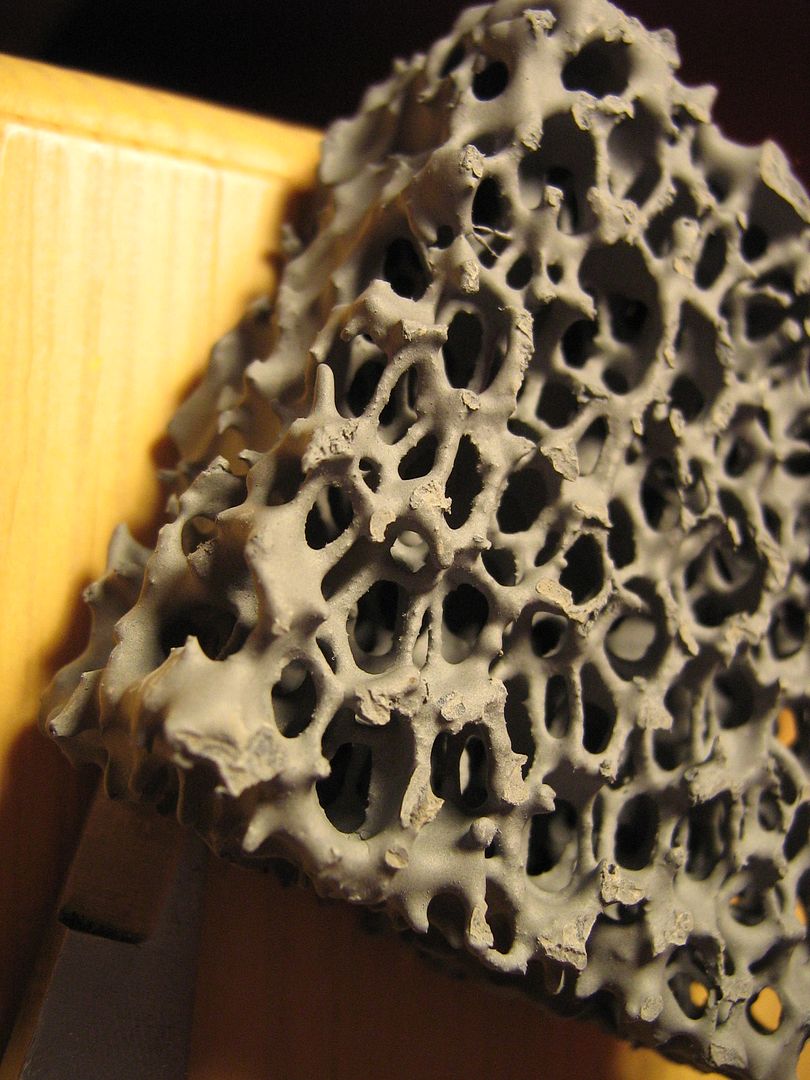
An example of the inline filters - these trap any dross in the metal, they are a ceramic foam,

Image

Image

Hopefully that will answer some more questions,

For a summary please view the video below, 1.30- 2.04 sums up the above a little better in visual terms,

http://www.youtube.com/watch?v=AdcoVurVY30


Regards,

Brian Garvey.
Last edited by Brian.G on 04 Sep 2013, 22:33, edited 1 time in total.
If you think you cant, you wont, If you think you can, you will

xpensive
214
Joined: 22 Nov 2008, 18:06
Location: Somewhere in Scandinavia

Re: F1 Cylinder Head Design and Pneumatics, a closer look

Post

Amazing stuff Brian, I stand in awe.
"I spent most of my money on wine and women...I wasted the rest"

Brian.G
334
Joined: 10 Dec 2010, 23:52
Location: Ireland
Contact:

Re: F1 Cylinder Head Design and Pneumatics, a closer look

Post

xpensive wrote:Amazing stuff Brian, I stand in awe.
Hopefully It will make things a bit clearer.

Casting was once, and I do believe still is considered a 'black art' mainly because it takes experience in what works, and what wont.
Computer simulation of mould filling has done away with a lot of these skills now but I still think it is really important if you are involved with casting to know the general laws. If only to shorten time spent doing the simulations so that one would know where to place the basic items as a sim start point, runners, gates, chills , etc.
A good caster will right away have a fair idea where to locate the important bits for a good part in a bang, bang, bang, methodology, a few runs on the sim after + a few tweaks and away you go to a test pour.

Here is an example of a sim, spot the cold fronts meeting in the bottom of part 40 seconds in, and again at 55 seconds at the top - you will then see that these cold fronts are flushed out of the part, and into the riser banks as discussed above,

https://www.youtube.com/watch?v=IFpLYUOJuTY

Brian,

ps, I am in no way associated with software used in the video.
If you think you cant, you wont, If you think you can, you will

Billzilla
11
Joined: 24 May 2011, 01:28
Contact:

Re: F1 Cylinder Head Design and Pneumatics, a closer look

Post

Good stuff, thanks Brian.
Can you please post it in the other thread on PF?

xpensive
214
Joined: 22 Nov 2008, 18:06
Location: Somewhere in Scandinavia

Re: F1 Cylinder Head Design and Pneumatics, a closer look

Post

Brian.G wrote:
xpensive wrote:I cannot believe the valve-cover and front face are sand-cast surfaces, neither machined?

http://www.google.com/search?q=renault+ ... 680%3B1095
Its hard to tell on the gear cover, it looks like a billet machine item, but the cam cover is defiantly sand cast yes.
...
If you're planning to make a more than a few, how about shell-casting those cam-covers?
"I spent most of my money on wine and women...I wasted the rest"

Brian.G
334
Joined: 10 Dec 2010, 23:52
Location: Ireland
Contact:

Re: F1 Cylinder Head Design and Pneumatics, a closer look

Post

xpensive wrote:
Brian.G wrote:
xpensive wrote:I cannot believe the valve-cover and front face are sand-cast surfaces, neither machined?

http://www.google.com/search?q=renault+ ... 680%3B1095
Its hard to tell on the gear cover, it looks like a billet machine item, but the cam cover is defiantly sand cast yes.
...
If you're planning to make a more than a few, how about shell-casting those cam-covers?
You could do, but If I was doing a cover such as this I'd probably cnc machine from billet since its a 'fairly' simple part with not much internal ways bar the tapered coolant tube. I see a fair few of the newer F1 covers are machined this way, and not cast. A good example below of a billet cover, taken again, in Maranello.

Image

Brian,
If you think you cant, you wont, If you think you can, you will

Greenlight
2
Joined: 06 Sep 2013, 06:54

Re: F1 Cylinder Head Design and Pneumatics, a closer look

Post

Brian,

This is truly a very rare and informative look into a cylinder head that the majority of the world will never have access to and I want to personally thank you for your efforts.

I noticed that others have asked for valve seat angles and you agreed to try and obtain accurate angles. Thanks.

If possible I would like additional details about the valves and ports. Any information that you can provide will be appreciated. Here are some things I am interested in knowing on both the intake and exhaust side:

Valve Diameter, valve margin thickness, valve seat angle and width, back cut angle/shape and width, stem minor diameter, stem diameter.
Port throat diameter, distance from bottom of valve seat to minimum throat diameter.
Port SSR (short side radius) radius, port min. and max. CSA (cross section area), distance from valve seat to apex of SSR.
Valve angle(s) relative to head sealing surface.
Port angle (approximate, relative to head sealing surface).
Approximate distance between valves (while seated).
Approximate distance between valve and bore ("shrouding" distance, while seated).
Approximate camshaft lift and duration.
Cylinder head port flow (preferably with radiused entry and at 28" H2O pressure differential).

I realize that I am asking a lot and I know you may not be able to provide all of the information that I requested.

I will appreciate any data that you can provide.

johnny99
1
Joined: 09 Apr 2009, 19:28
Location: Killucan Westmeath Ireland

Re: F1 Cylinder Head Design and Pneumatics, a closer look

Post

As a friend of Brian's I hope people appreciate the amount of work and time this has taken and the attention to detail he has in every task he completes. As one of the few Irishmen on here, I am very proud to call him a friend, keep it up Mr G

John

Brian.G
334
Joined: 10 Dec 2010, 23:52
Location: Ireland
Contact:

Re: F1 Cylinder Head Design and Pneumatics, a closer look

Post

Greenlight wrote:Brian,

This is truly a very rare and informative look into a cylinder head that the majority of the world will never have access to and I want to personally thank you for your efforts.

I noticed that others have asked for valve seat angles and you agreed to try and obtain accurate angles. Thanks.

If possible I would like additional details about the valves and ports. Any information that you can provide will be appreciated. Here are some things I am interested in knowing on both the intake and exhaust side:

Valve Diameter, valve margin thickness, valve seat angle and width, back cut angle/shape and width, stem minor diameter, stem diameter.
Port throat diameter, distance from bottom of valve seat to minimum throat diameter.
Port SSR (short side radius) radius, port min. and max. CSA (cross section area), distance from valve seat to apex of SSR.
Valve angle(s) relative to head sealing surface.
Port angle (approximate, relative to head sealing surface).
Approximate distance between valves (while seated).
Approximate distance between valve and bore ("shrouding" distance, while seated).
Approximate camshaft lift and duration.
Cylinder head port flow (preferably with radiused entry and at 28" H2O pressure differential).

I realize that I am asking a lot and I know you may not be able to provide all of the information that I requested.

I will appreciate any data that you can provide.
I will provide all of the above next week, no problem.

John, there has been a lot of good will with this thread so I have no doubt people appreciate it - thanks again all.
Im even prouder to be able to call you a friend, so hopefully that says a lot about you too.

Brian,
If you think you cant, you wont, If you think you can, you will

Billzilla
11
Joined: 24 May 2011, 01:28
Contact:

Re: F1 Cylinder Head Design and Pneumatics, a closer look

Post

Brian.G wrote:I will provide all of the above next week, no problem.
That will be most interesting, thanks.

Post Reply