Paul,PVDL wrote:Brian, WOW! Thanks for this thread. I got more out of this than reading a years worth of RET magazine!!
Couple of questions...
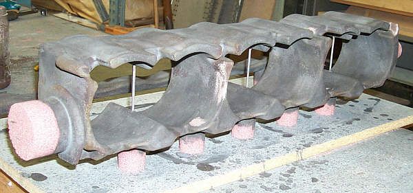
Regarding the water cores, which sand technique is used to make them?
Are they baked before or after joining the segments to each other and what type of glue/cement is used in the process?
Also the nut seats for the head studs are quite a trick to machine. I can guess how they did it, but I wonder what level of precision they accomplished. Maybe it doesn't matter if they used spherical washers under the nuts?
Anyway, fascinating stuff and many thanks to you!!
Cheers, Paul
If this is the case you will love the next thread - but more on that in a week or two.
Regards the cores, I cannot guess which cores they used, but they were air set or sodium silicate bonded co2 cured.
As for the glue, I use an Isopropyl alcohol based adhesive since nearly all my core work is with sodium silicate bonded sand - since water is used to wash out these cores(it breaks down the bond)you cannot really used a waterbase glue for bonding as the bond is less robust - BUT - water based glue is sometimes used having said that as it is more environmentally friendly. There are a load of glues out there though, the main thing with all of them is to make sure they are dry before pouring as any steam or gas created if alloy hits semi dry glue will make either a gas pocket, or a blow hole.
All cores are set/dried before bonding/building.
The nut seats are pretty straightforward to machine, I dont know what way you have guessed but Im certain these were done with a back counterbore cutting tool. Other names rear spot face tool, back spotfacer, rear counterborer.
The method is drill all head bolt holes from the block side. These get reamed to a high surface finish. A long slender tool the same diameter of drilled hole is then passed all the way through until the tip exits under the cam trays. The tool can either have a flap that is then hinged out against a pin in bar pocket with contains a carbide insert and the spot facing can commence. The machine is powered down, the flap c/w insert hinged into boring shaft pocket and the entire bar withdrawn again ready for insertion into next hole. That is one method, another is grubbing a mini cutter block onto the end of the shaft once it is passed through.
A while back I designed a new type of tool for doing same without all the fiddling whereby the long slender bar was inserted into head bolt hole exited under cam area. The 12mm bar was drilled in the center and the cutter end was turned down to form a small shoulder. The end section was 10mm in diameter and 20mm long. The bar was counterbored on the exit end 6mm in diameter to a depth of 15mm. On the inside of this counterbore a groove was cut similar to one for an internal circlip but wider(2mm wide). This groove went to a depth of 1.75mm leaving a wall thickness of just .25mm in that area. The end of the counterbore was blocked off with a tig welded plug. The bar was inserted into headbolt hole to the required exit depth. The mini cutterblock was placed on the end of the bar and the hydraulic pressure turned on. This fed oil into the bar - down its length and into the end at cutter block. The oil pressure slightly swelled the thin area at groove locking the block on. It proved to be very fast and less fiddly that the hinged flap method. Oil was introduced into the bar though a radial drilling via a sealed live manifold near collet similar to how coolant is fed into deep drills.
Sadly I cant share any pictures of the above as someone else was paying at the time.
There are many ways of doing back counters but it all depends on how many you have to do, whos paying, and what machines you have to work with. Some can even actuate the hinged flap with a pull/push rod similar to the pull stud drawbar affair.
Heres an example of an auto spotter,
http://www.heuletool.com/pages/catalog/images/18.pdf
Photobucket is acting up the last day or two but as soon as its back Ill post the rest of the basic port dimensions,
Brian,