A paperboard Lotus E21

Post here information about your own engineering projects, including but not limited to building your own car or designing a virtual car through CAD.
User avatar
Shrieker
13
Joined: 01 Mar 2010, 23:41

Re: A paperboard Lotus E21

Post

Paul,

Admit it. As soon as you joined Red Bull, you screwed up SO BAD with the RB10 that as soon as it hit the track, you started eyeing a job at Lotus :lol:
Education is that which allows a nation free, independent, reputable life, and function as a high society; or it condemns it to captivity and poverty.
-Atatürk

User avatar
PaulB
72
Joined: 17 Oct 2010, 09:52
Location: Graz/Austria
Contact:

Re: A paperboard Lotus E21

Post

Hey Chaps,

over the last few weeks I was working a bit on the engine and finished off the nosecone. Of course, all beside RB10 troubleshooting.

The nosecone was actually not planned to build that early, but some circumstances forced me to build the nosecone now. This circumstances are some kind of a "secret project" which I'll show you in a few weeks. Target date is first week of April. Wait and see...

Engine: Front wall of the engine block is almost finished. Mounting points to the chassis are all done and looking very stiff. Not much to tell about the engine any more. Apart from the to expect ultra high grade of detail.

The nose is also a huge improvement compared to the RB7 one. The laminate thickness is much more realistic (not that fat as it is at my RB7). However, the nose is very stiff and the nosepins are very rigid. The front wing pylons were also a bit of a weak spot at the RB7. On this nose, I reinforced the pylons with a steel wire each side and provided another tube for picking up the FW mountings. The shape of this nose was highly complex. Especially the bulge under the nosetip and the step were very difficult to get properly done. But everything worked out quite well without any big problems. The nose is probably a bit lower than the original, but at least it's within the regulations.

Current state of the RS27 engine. I got a bit of heat damage at the lh side of the engine front. It can happen that I leave it like this to show a few signs of wear.
Image

The first attempt to attach the engine to the chassis was highly successful. The stiffness of the assemblage is astonishing. The tech regulations require 6 M10 bolts to fix the engine to the chassis. In my case the engine is fixed by six steel pins.
Image

Nose cone drawing. Loads of regulation lines to start. You can clearly see the bulge under the nosetip which wasn't there every race. Means, Lotus had at least two nose speifications over 2013. I did not made a lot of research in that direction. As I know that I'll build the Belgian specification there is no need to know how many different noses they used over the season.
Image

Structural nose part. Here you can see the crashbox and at the left there is the jig to bond in the nosepins.
Image

Bonding process of the nosepins. That's always one of the most critical points of the build (as the nose should be removable). But everything went quite well to my full staisfaction.
Image

Templates for the black coating of the nose. From left to right: The sides and the lower part are one part (bulge included). Top cover is in the middle. The cutting edge was designed to be covered by the nice gold stripe. The strange looking part on the very right hand side is a front wing pylon.
Image

First attempt to fit the nose.
Image

Here you can see the internals of the pylons. The rear tube is the structural beam, the front tubes are the pick up points for the front wing.
Image

Logo fitting...
Image

I'm getting better and better doing the paint jobs. The surface of the nose is almost perfect. A few small tweaks to be done, but in general it's a great finsih.
Image

Nothing to say about this...
Image

Chassis: E21-03; Cockpit badge
Image

That's it for now. Look forward to publishing my secret project!

Cheers,
Paul
"Being second is to be the first of the ones who lose!" - Ayrton Senna

Paul Bischof
Milton Keynes, UK
MK2 2HL
http://paulsf1.wordpress.com/

User avatar
humble sabot
27
Joined: 17 Feb 2007, 10:33

Re: A paperboard Lotus E21

Post

Absolutely inspiring.
the four immutable forces:
static balance
dynamic balance
static imbalance
dynamic imbalance

Schifty
-1
Joined: 04 Dec 2013, 18:54

Re: A paperboard Lotus E21

Post

Its a bit shameless we never saw the final result of any of your started work.... Redbull....Audi and now Lotus

User avatar
Shrieker
13
Joined: 01 Mar 2010, 23:41

Re: A paperboard Lotus E21

Post

Paul,

That looks even more amazing than the Red Bull RB7. You are no doubt getting better. I wonder how much more you can improve :)
Education is that which allows a nation free, independent, reputable life, and function as a high society; or it condemns it to captivity and poverty.
-Atatürk

Spirits of Senna
0
Joined: 13 Aug 2013, 04:36

Re: A paperboard Lotus E21

Post

Are those actual carbon fibre pieces used in the inner tub?

User avatar
PaulB
72
Joined: 17 Oct 2010, 09:52
Location: Graz/Austria
Contact:

Re: A paperboard Lotus E21 - Front Wing Design and Manufactu

Post

Good Morning Chaps!

A long time passed by since my last blog. Lot of work at the factory, some holiday and other stuff went on. Last week I restarted the work on my Lotus. What's up today: Front Wing Design and Manufacturing
Schifty wrote:Its a bit shameless we never saw the final result of any of your started work.... Redbull....Audi and now Lotus
What do you mean? I guess you've seent the final result of the RB7...?
Shrieker wrote:That looks even more amazing than the Red Bull RB7. You are no doubt getting better. I wonder how much more you can improve :)
It not just looks much more amazing than the RB, it is! ;)

So, building the Front Wing was great fun as usual and if you compare the result with the RB7 FW two years ago, you can see a huge step in detail work, in manufacturing quality and also in some minor engineering skills.

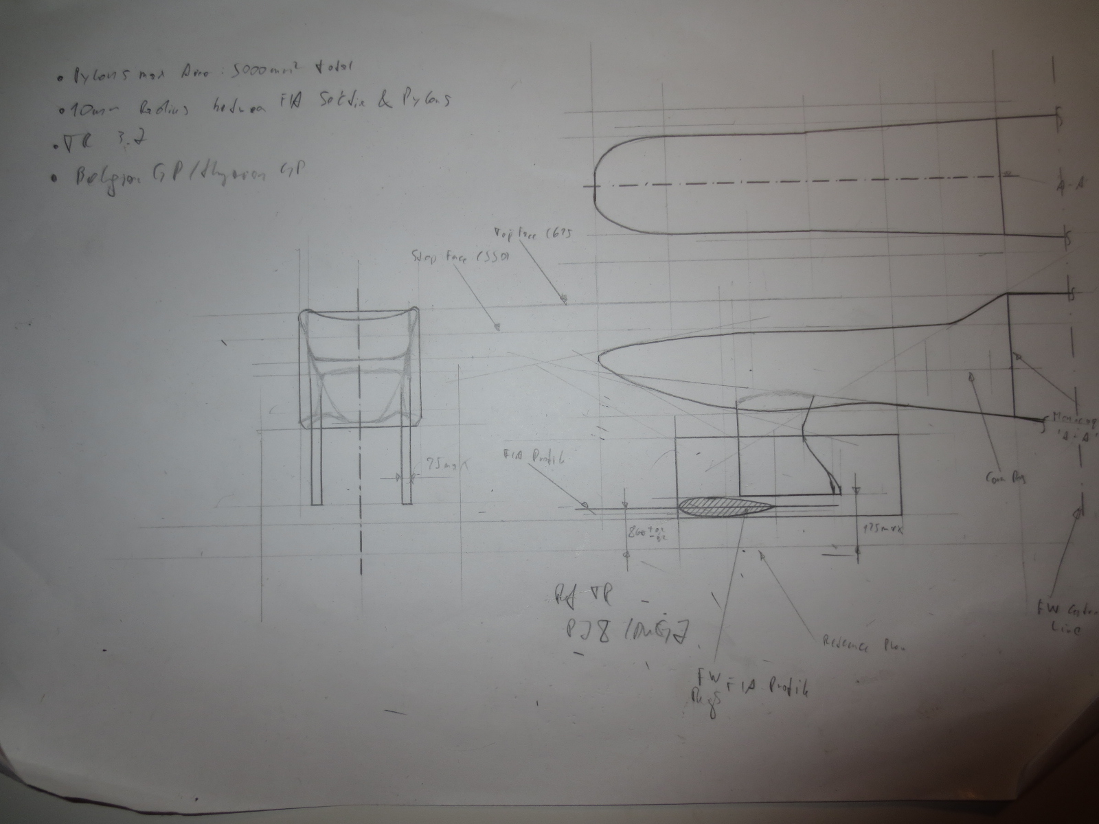
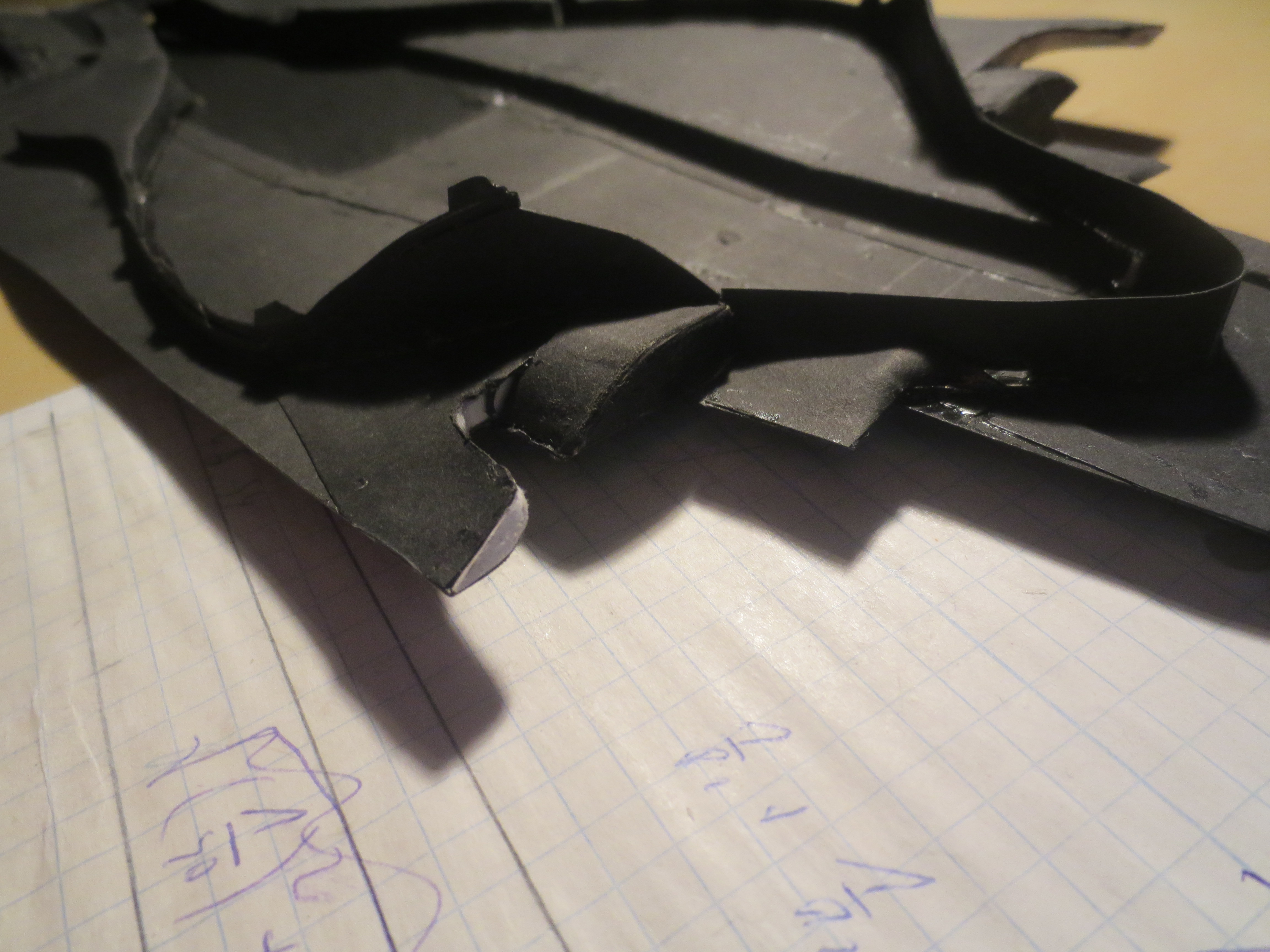
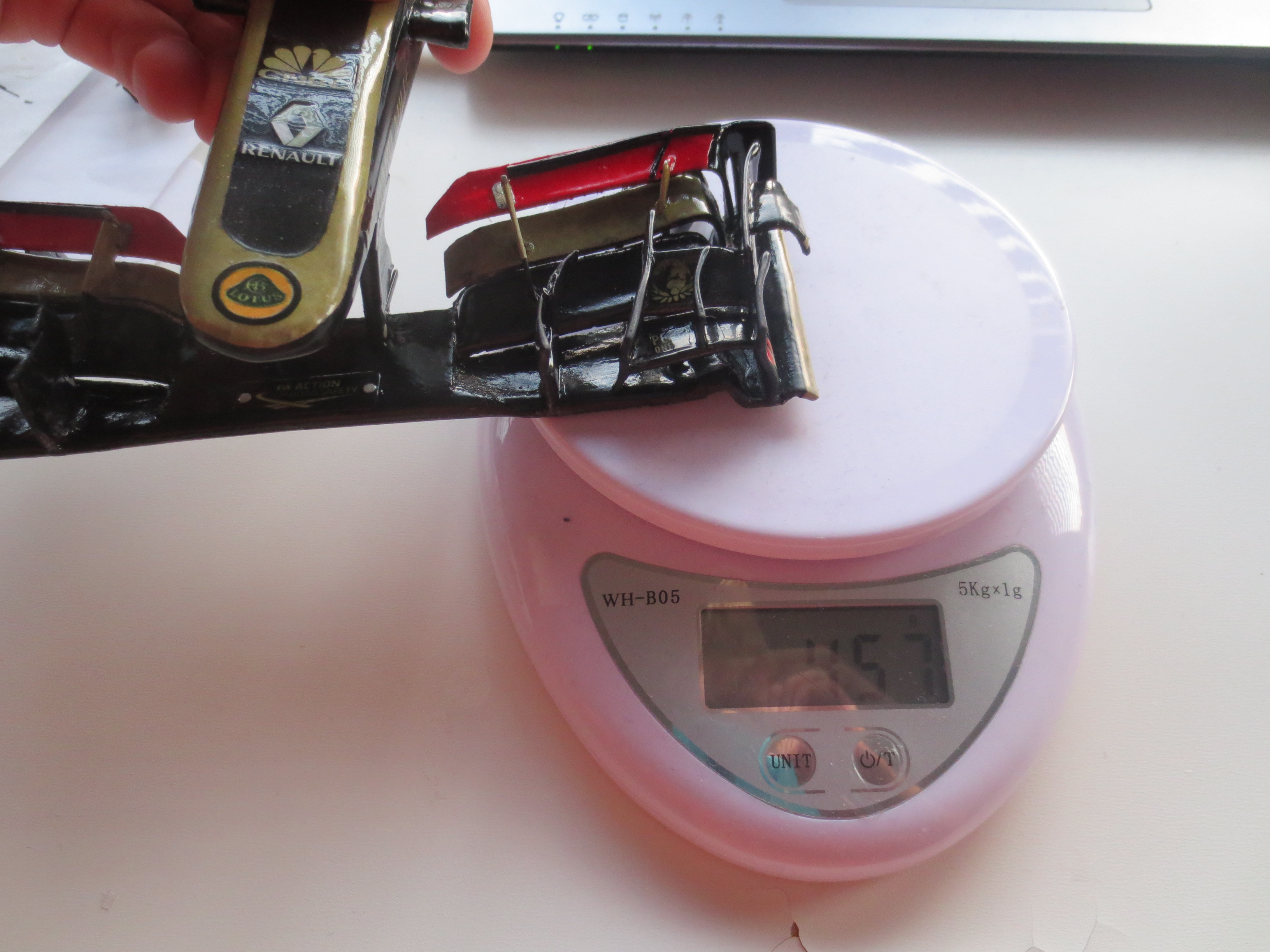
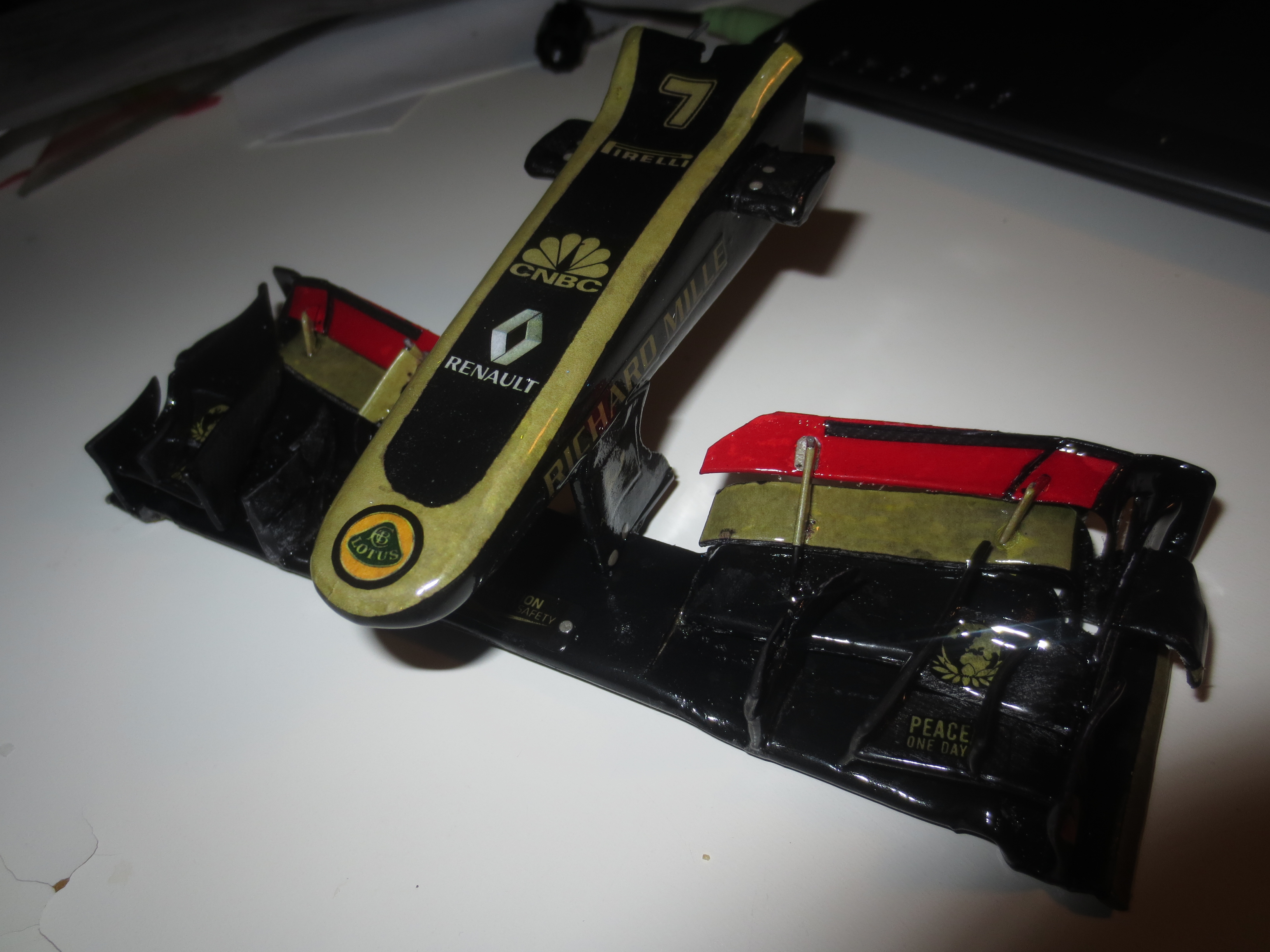
In general I'm very satisfied with the result of the FW. The surface quality could be a bit better in some places. But that's more a problem with restricted access as it's like under the small Front Flaps. The FW-Nose Assembly is with 49g pretty heavy. That's about 8.5% of the car weight. As you can see on a picture below, the stiffness of the wing is incredible. I did a simple deflection test where the wing resisted over 500g load which would be equivalent to 500kg(!) at the real car. I didn't measured any deflection of the wing, but the regs are telling you, that the wing should not deflect more than 10mm at a load of 100kgs. Maybe I do a proper deflection test on a rig somewhen. Just for fun (This statement is a bit sensless considering this is my hobby and should be fun all time).

Anyway, except a few dimension overrides conflicting with the front bodywork regulations, I'm pretty pleased with my new Front Wing. I hope the guys from Lotus are too.

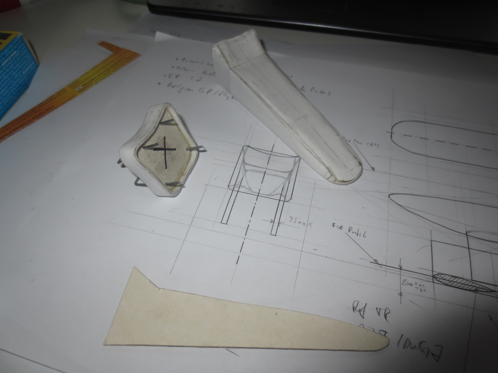
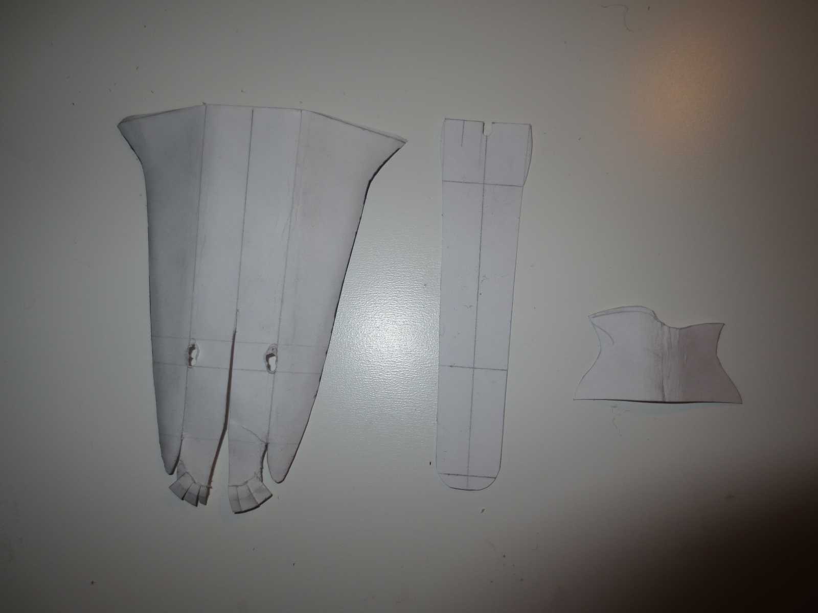
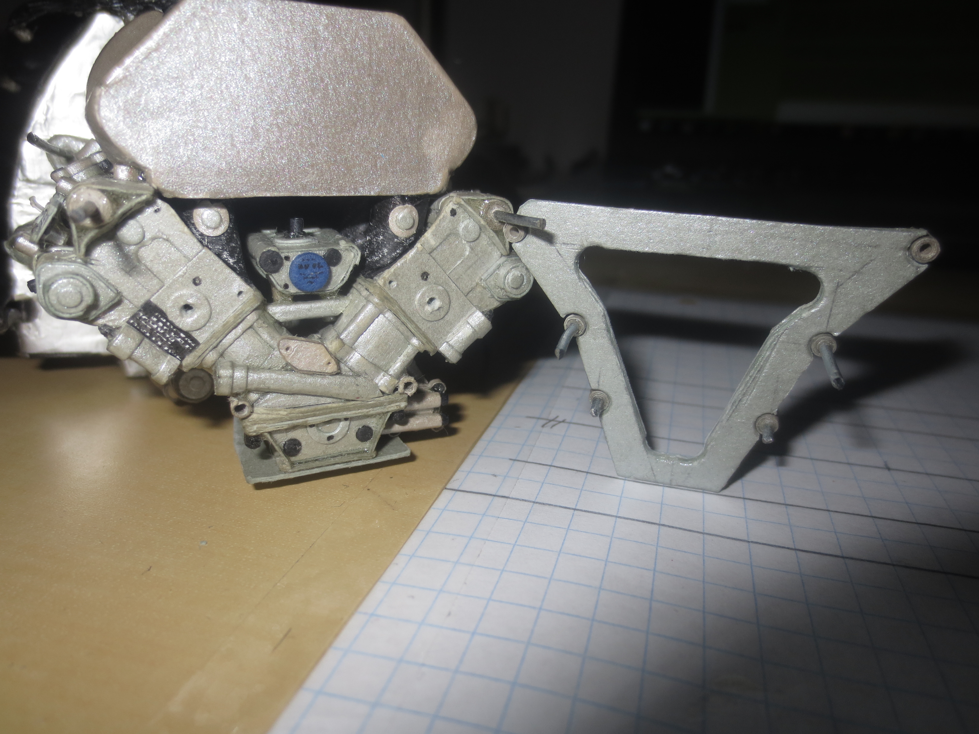
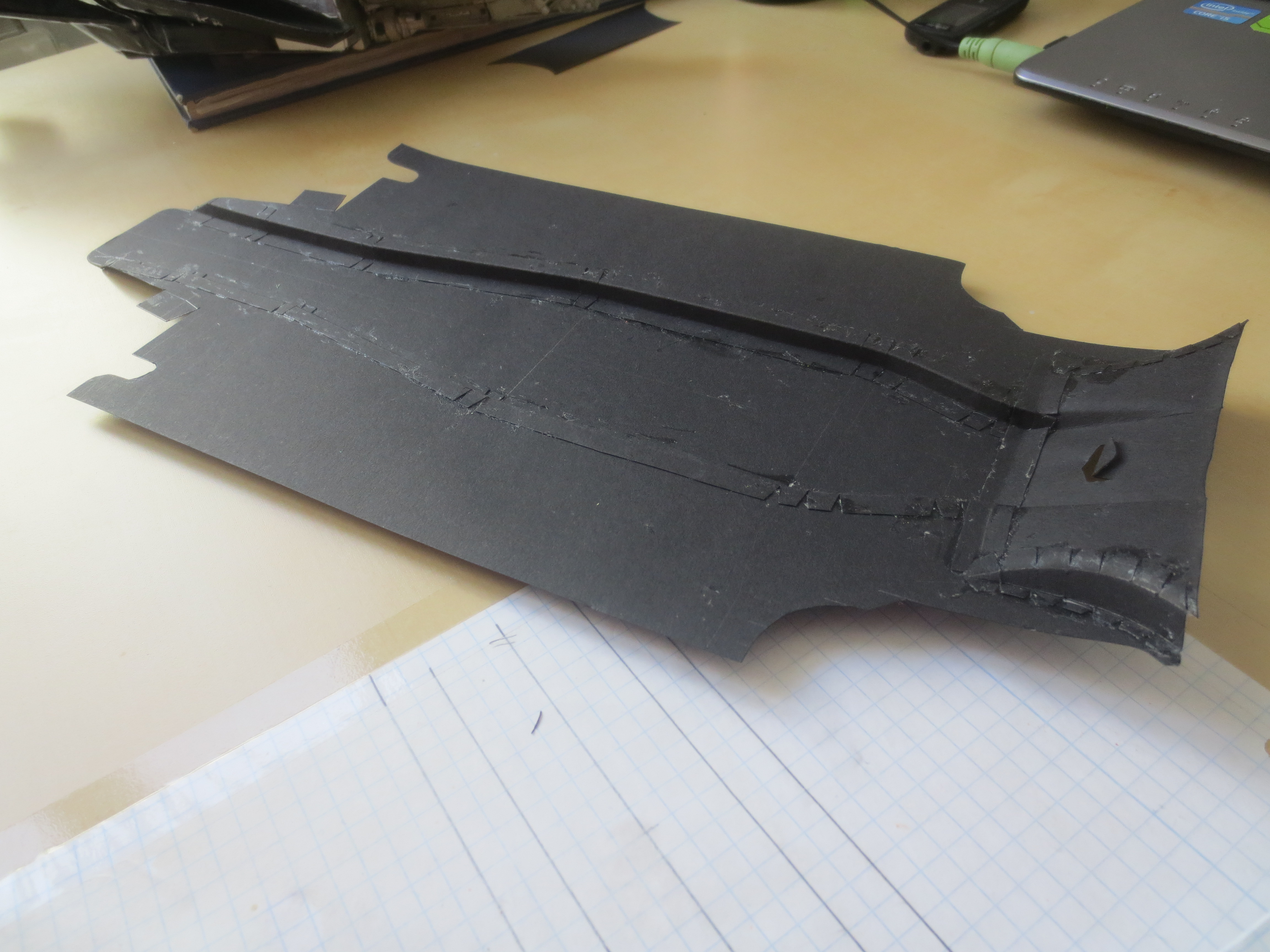
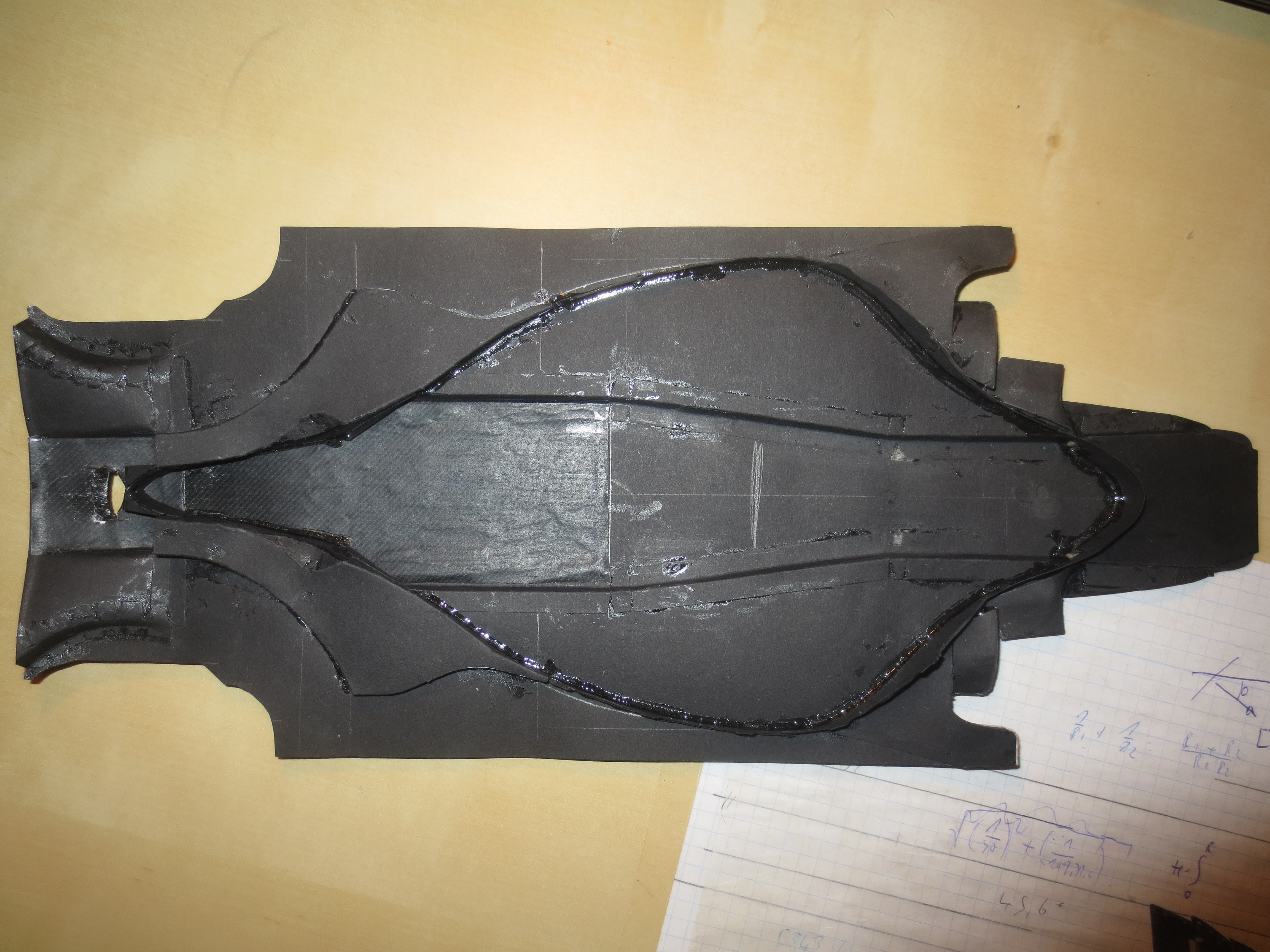
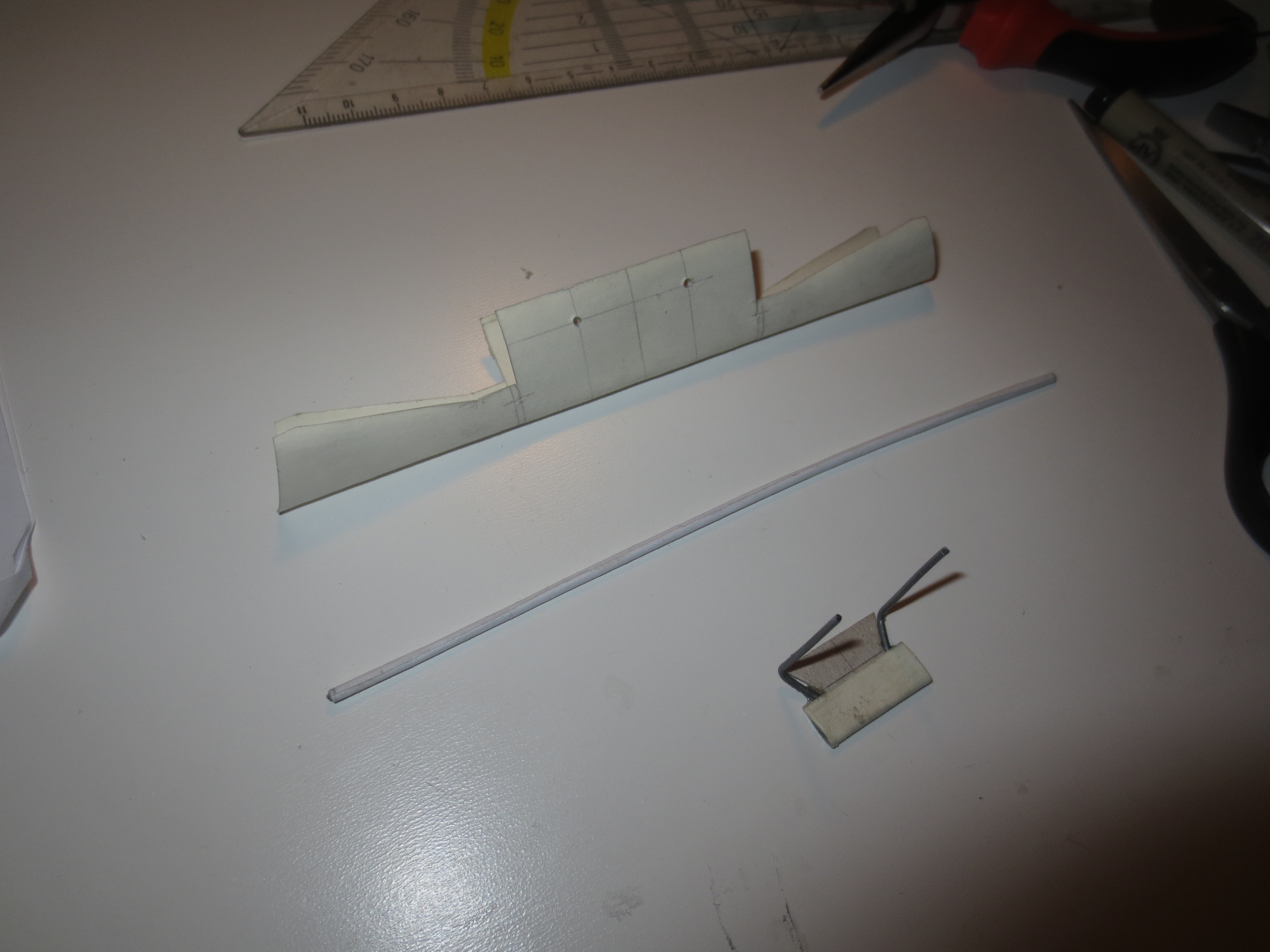
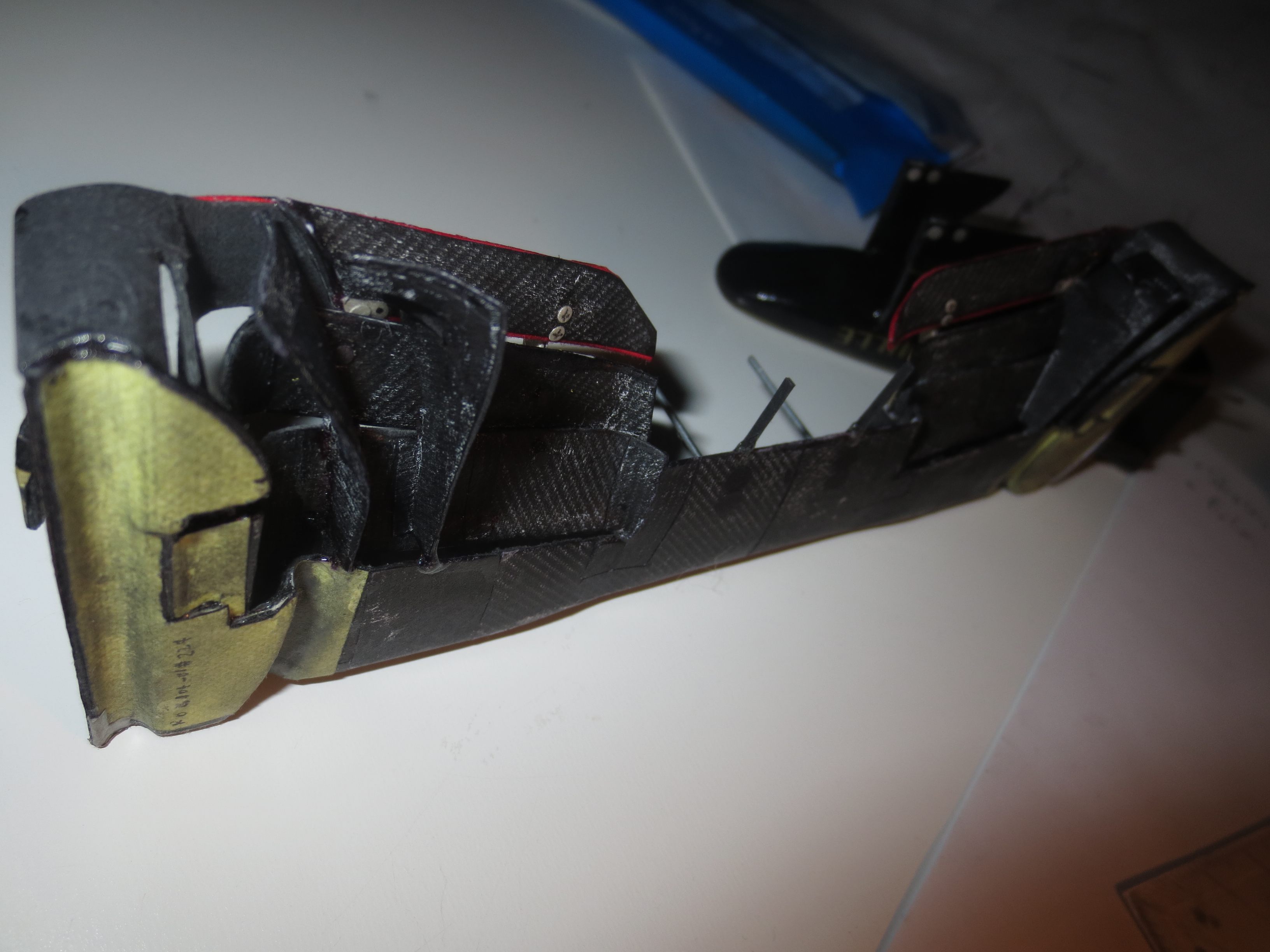
Start of the Front Wing Main Aerofoil. At the top you can see the main insert, which is actually just an offset of the aero surface. The tube in the middle is a paper wrapped 1.2mm steel wire (which you usually use to build fences) which gives the Main Aerofoil the needed bending stiffness around the X-Axis. The front insert is the connection between wing and Nose Pylons. This design secures, that the flexibility between the nose and the wing is reduced to a minimum, which was a huge problem on my RB7 where the connection was very groggy...
Image

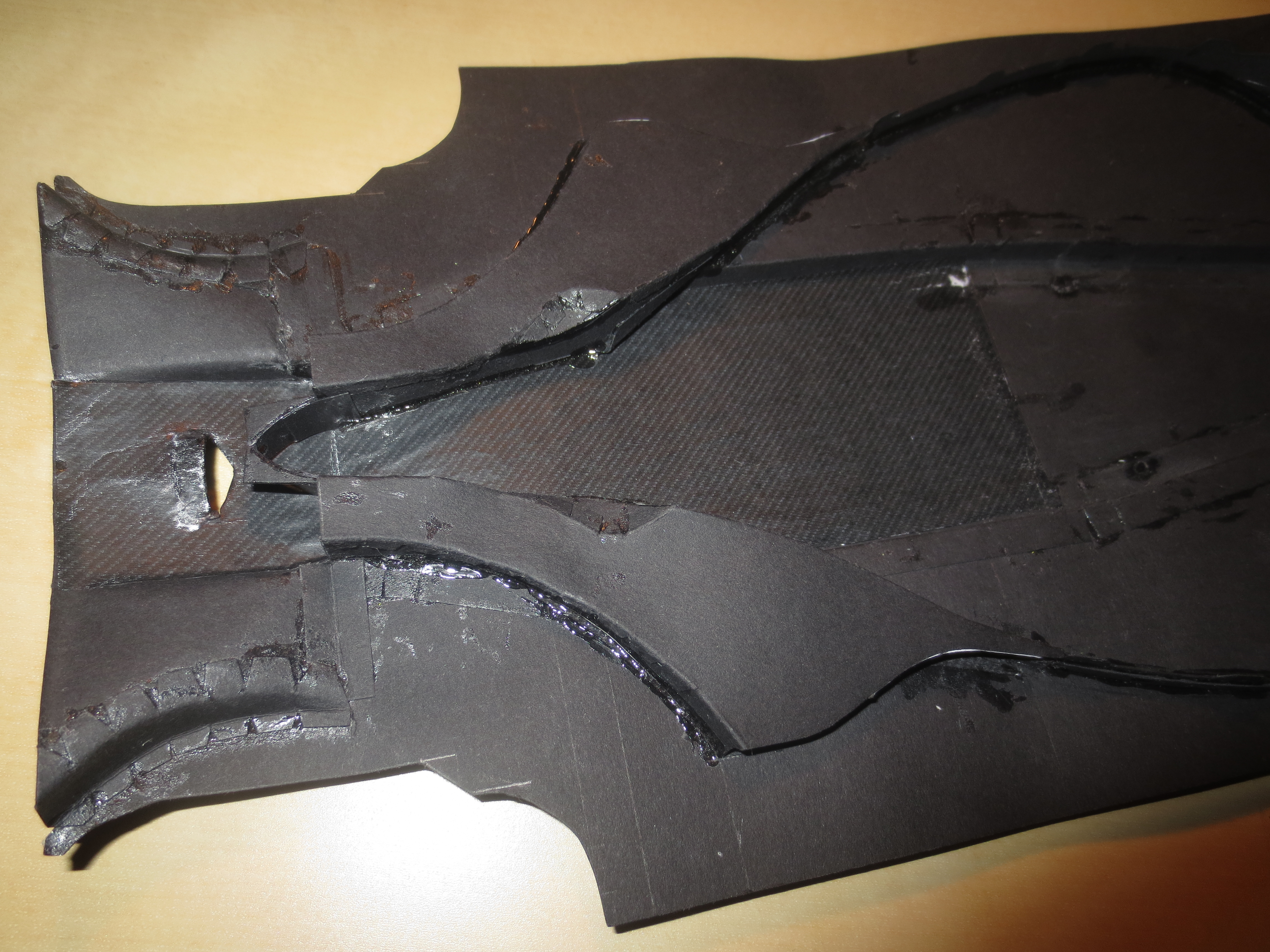
Here you can see the bonded in inserts in the FIA section of the Main Aerofoil. There are more inserts to come outside of the 500mm FIA middle section. The secondary flap on the Main Aerofoil, which is behind the forward aerofoil profile is later also reinforced with a steel wire. For this, I had to provide two additional circular holes in the rearward inserts.
Image

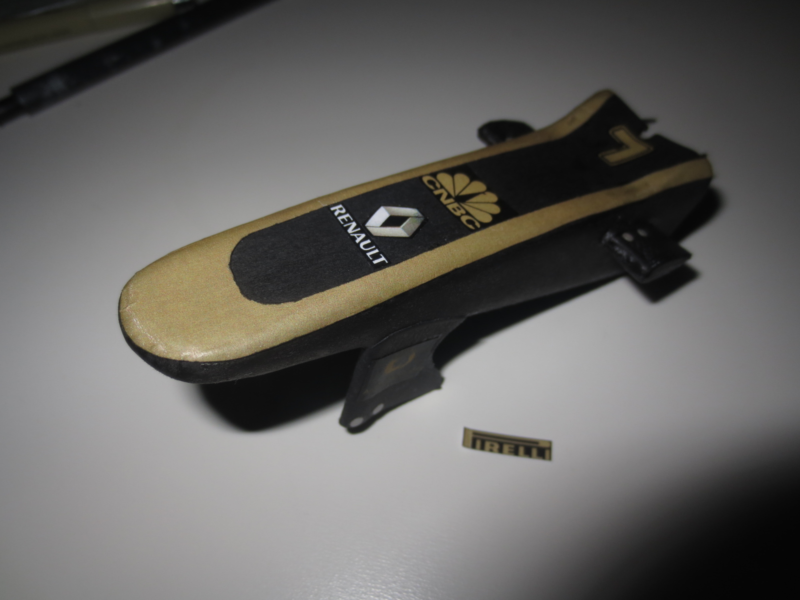
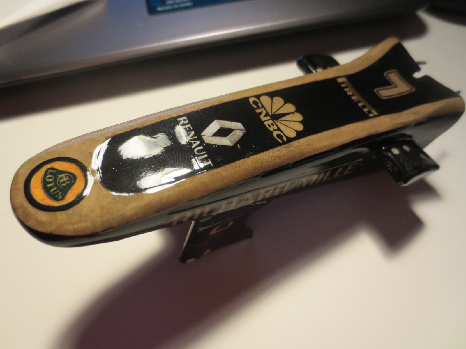
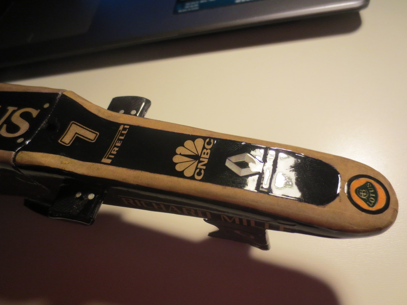
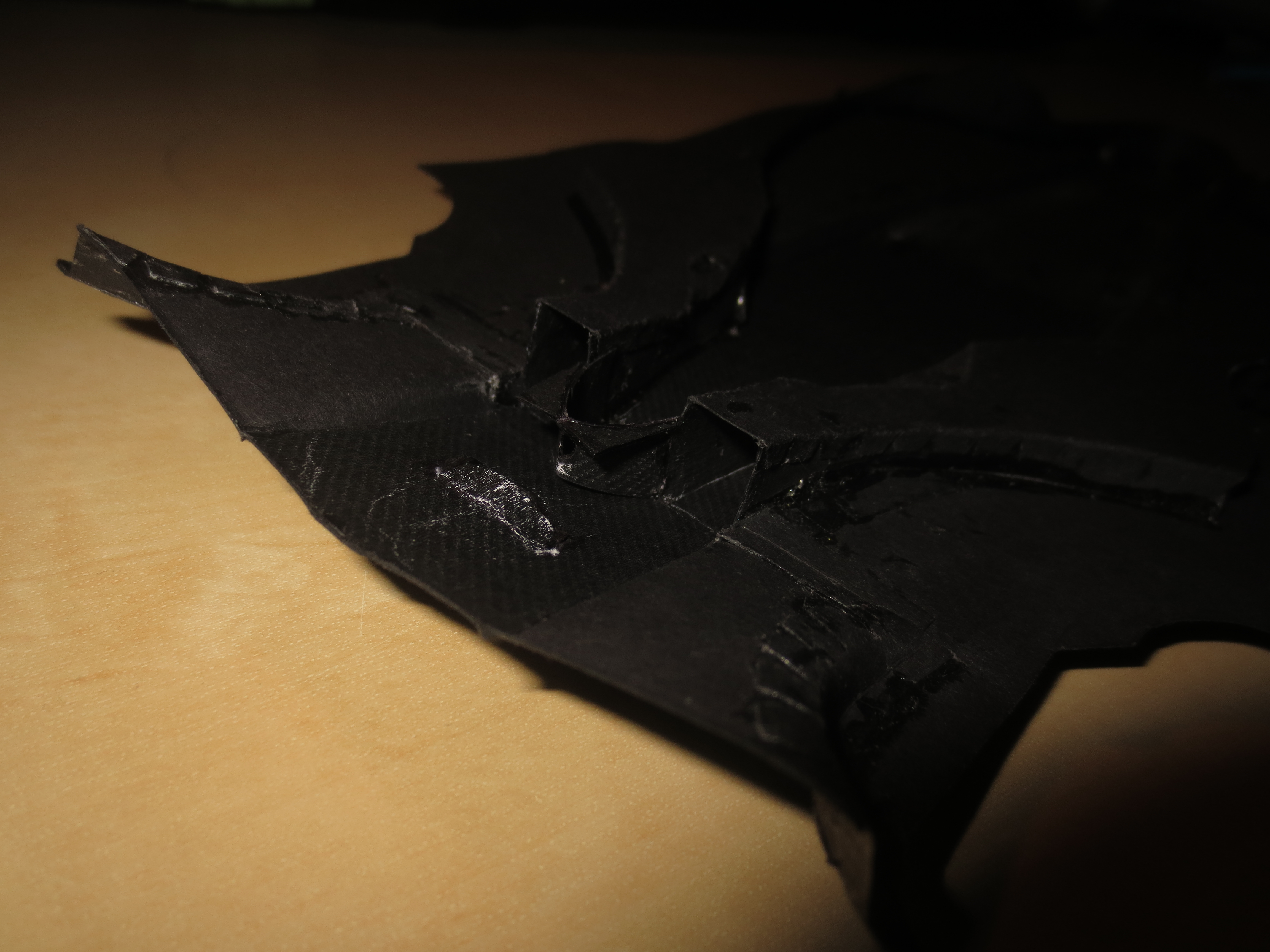
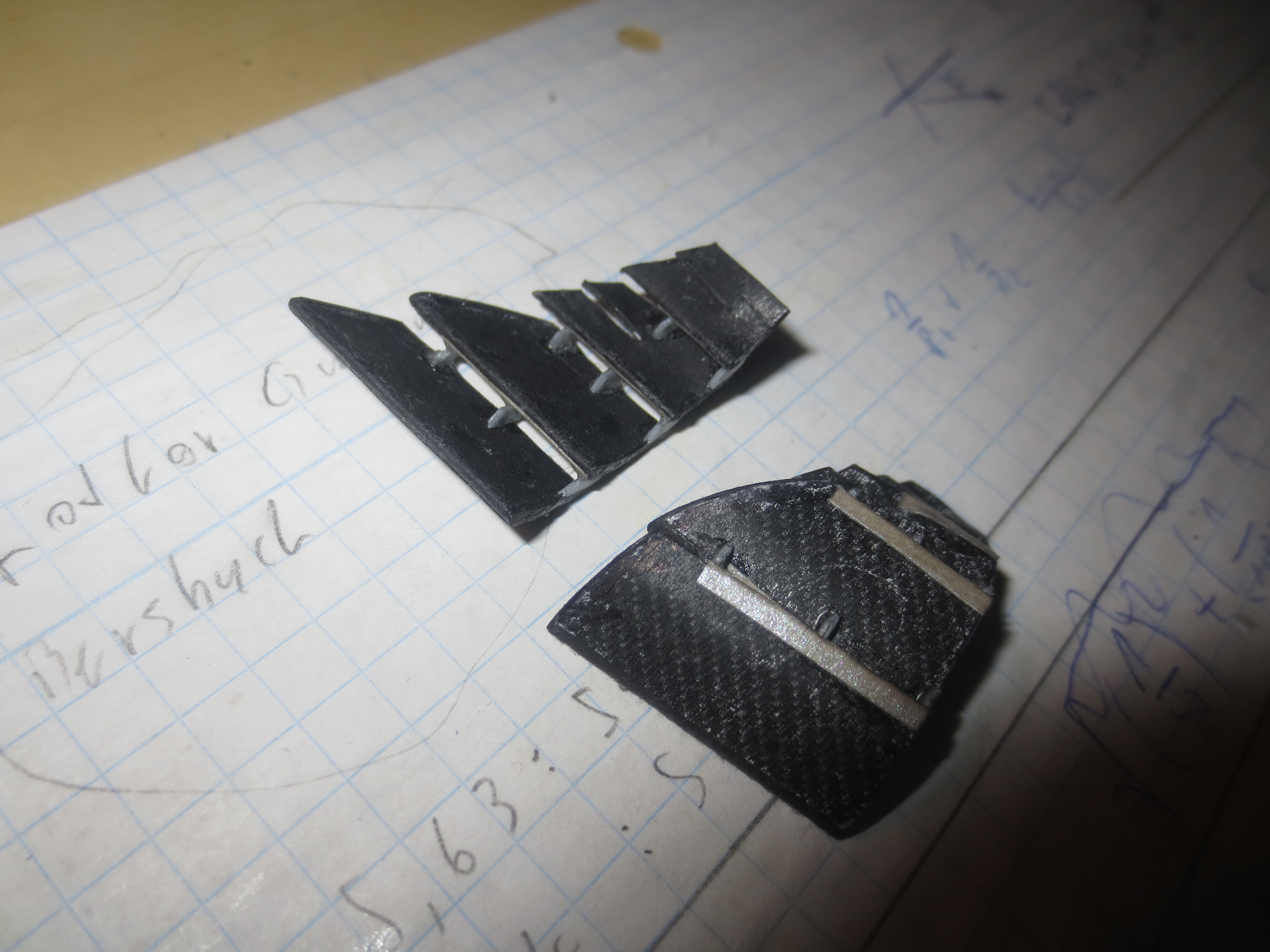
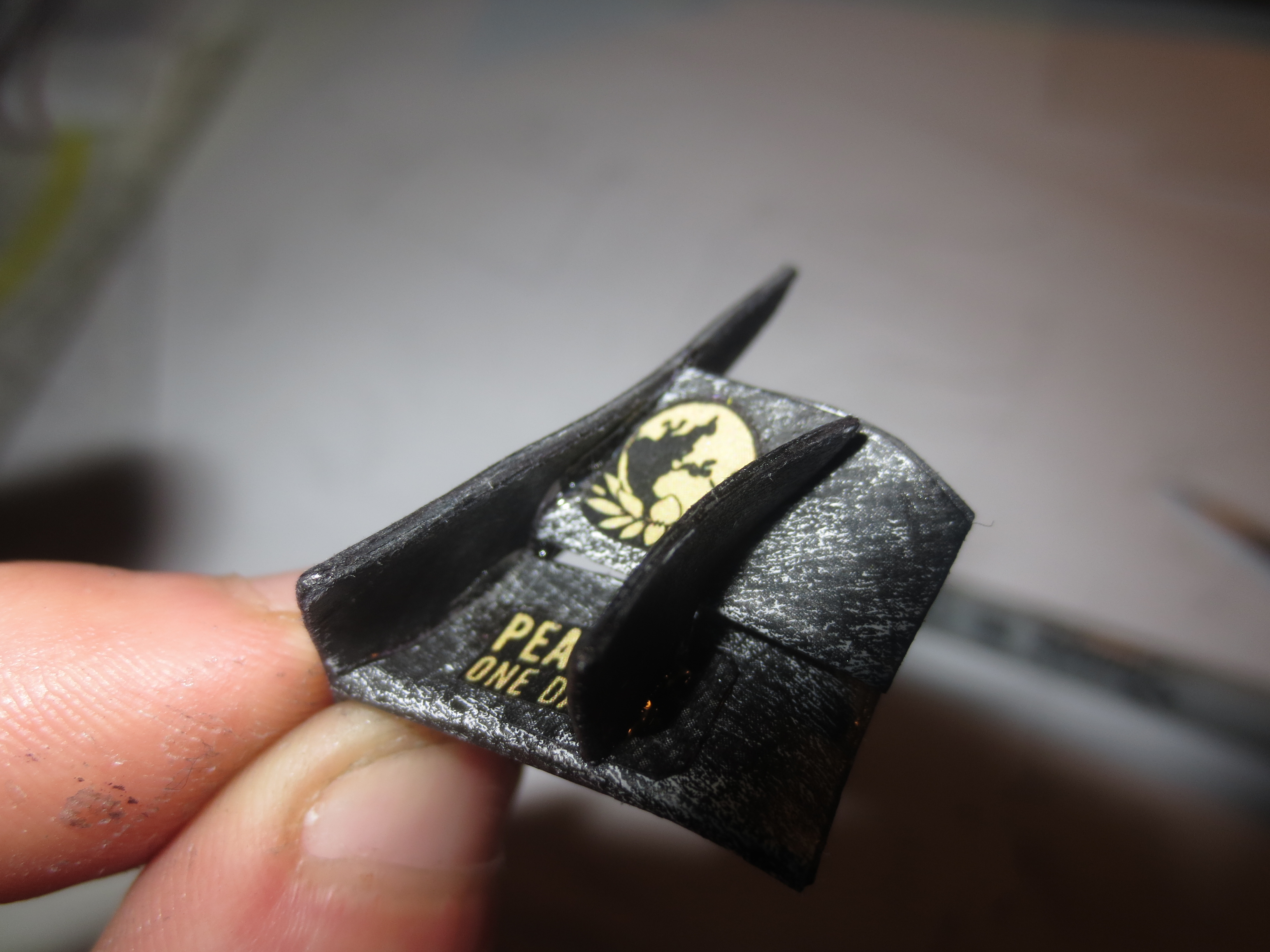
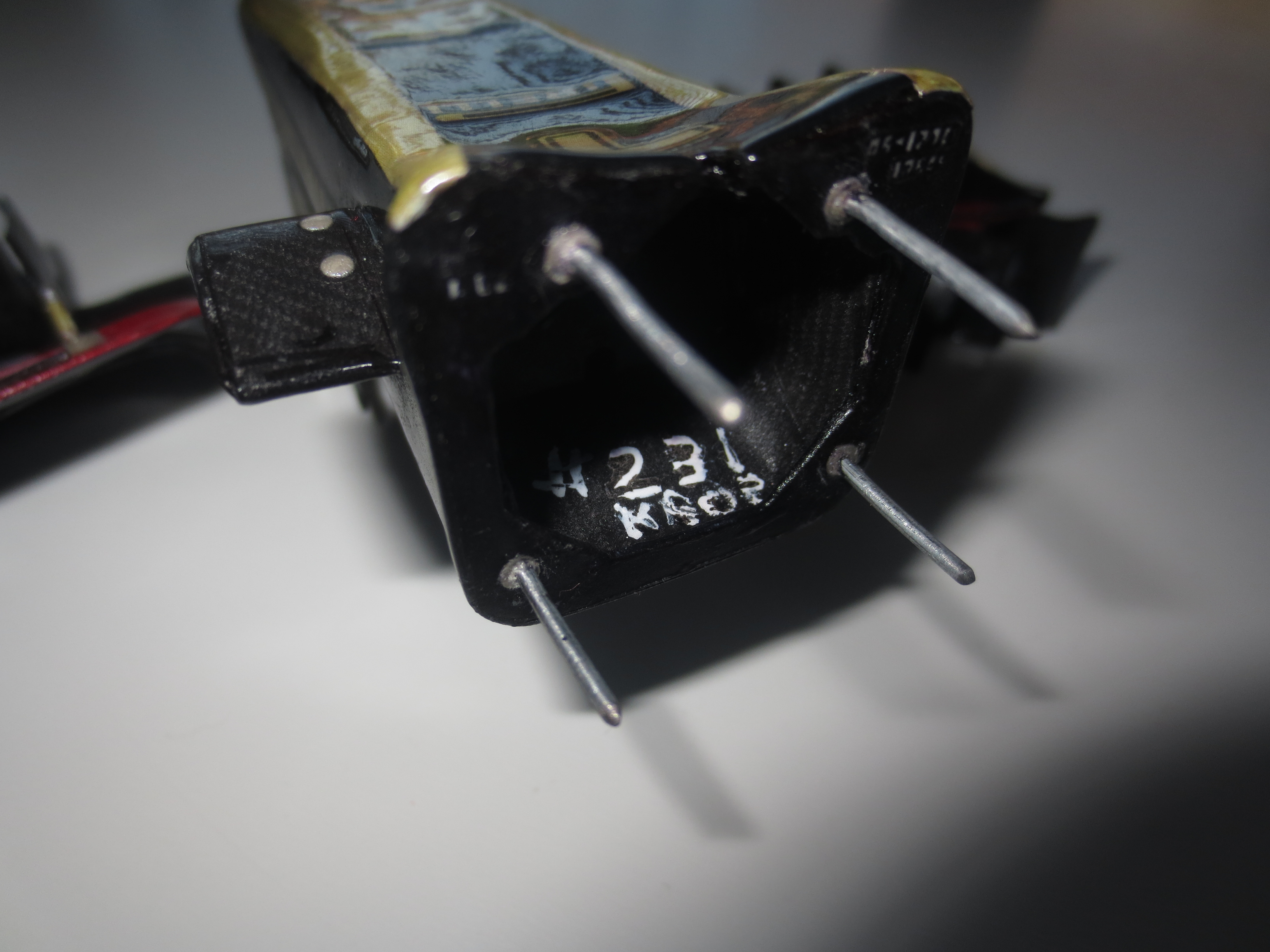
The Front Wing End Plates (FWEP) at the start stage. There are two inserts in it. You can see both of them in the endplate at the top of the picture. These inserts should secure, that the FWEPs have nice sharp trailing edges as well as nicely rounded leading edges all over the part.
Image

From the laminate point of view, the front wing Main Aerofoil is probably the most impressive element on a F1 car. As you can see in this pic, and believe me, I did the laminate exactly like it is at the real car, the layup is pretty complex. That's alyways a nice exercise for the stress guys.
Image

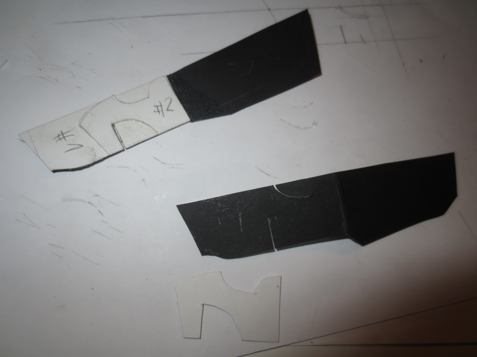
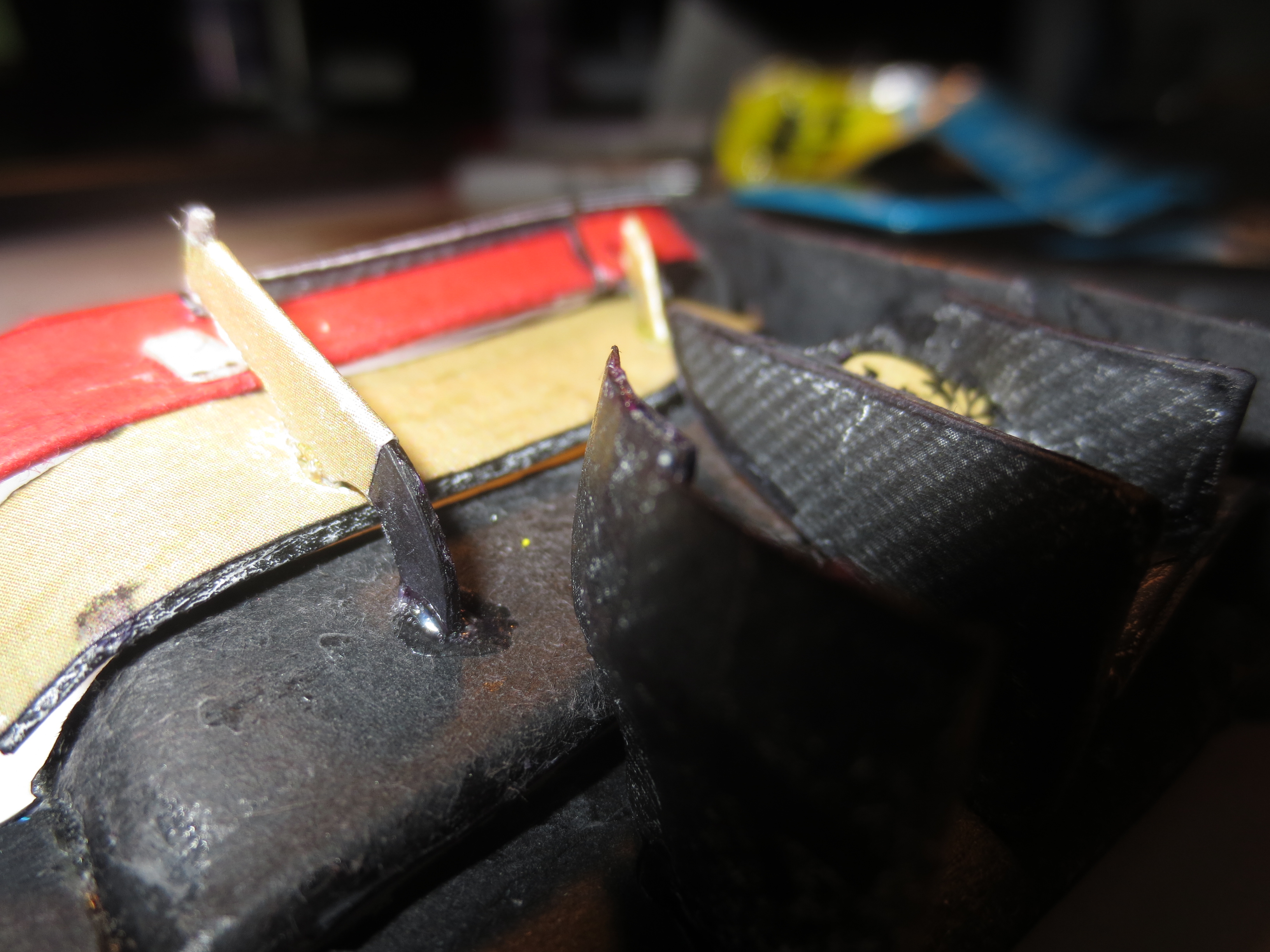
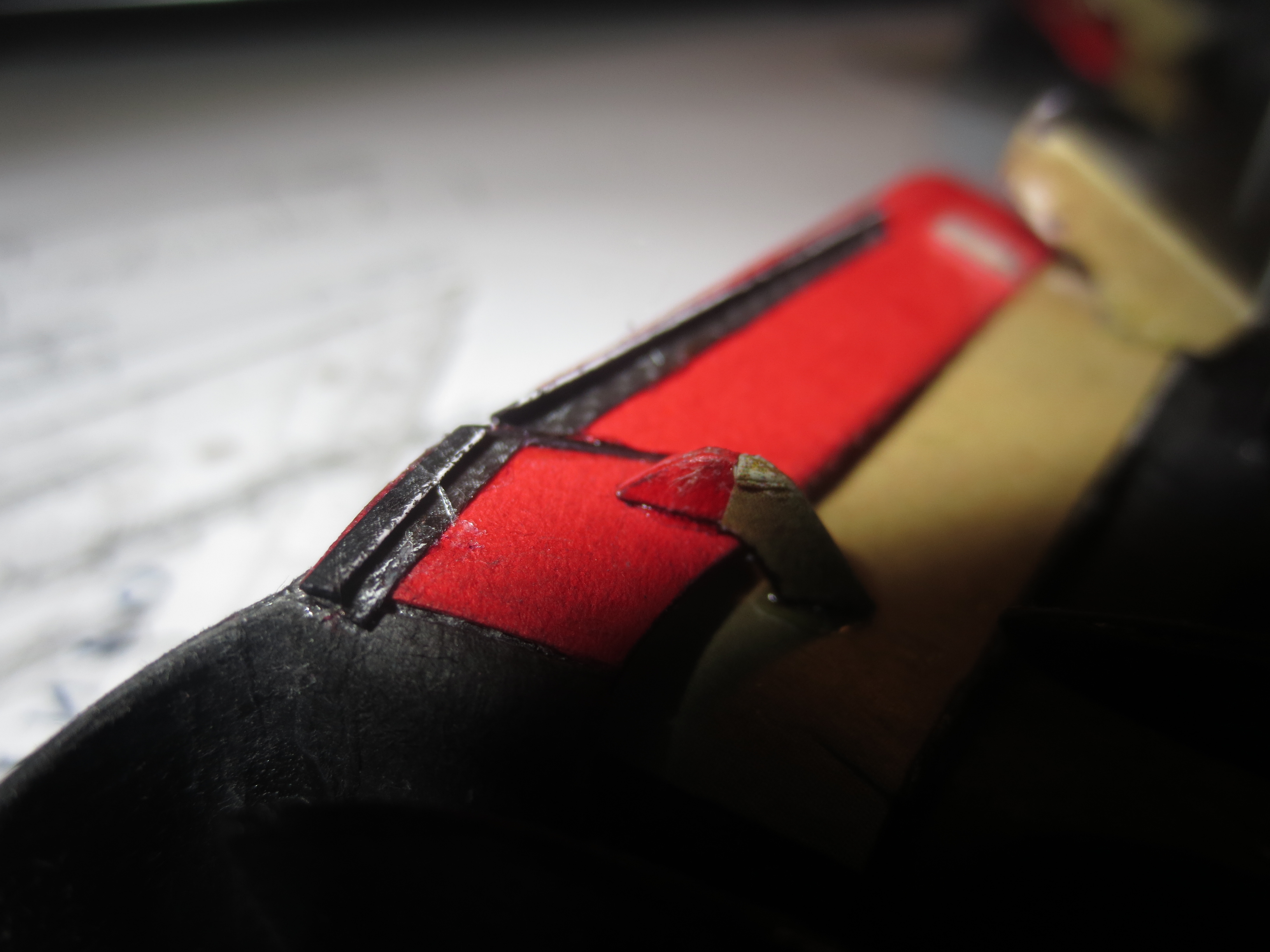
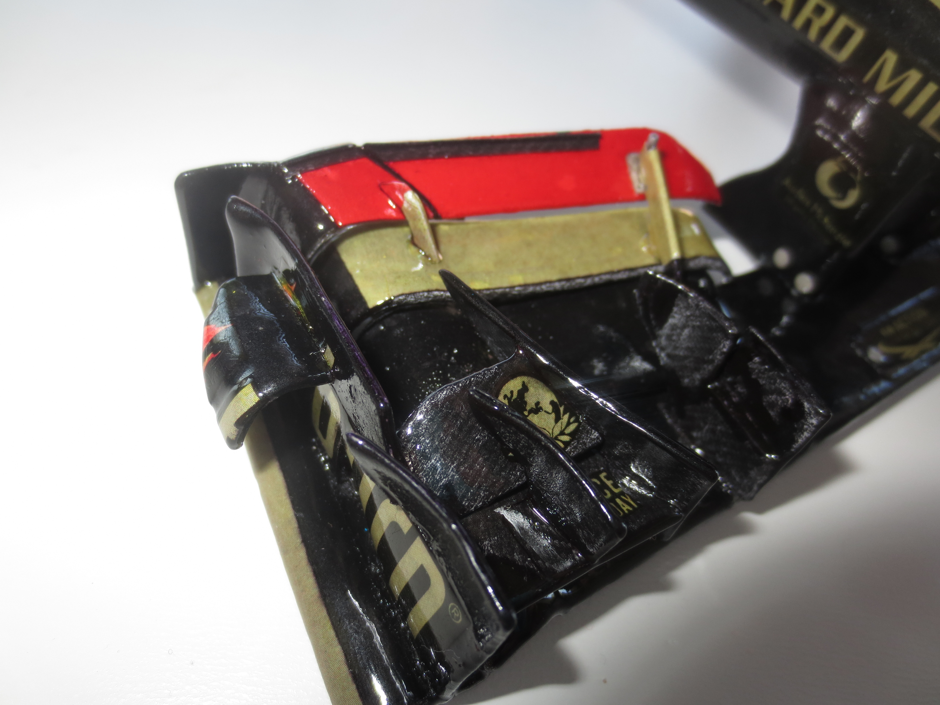
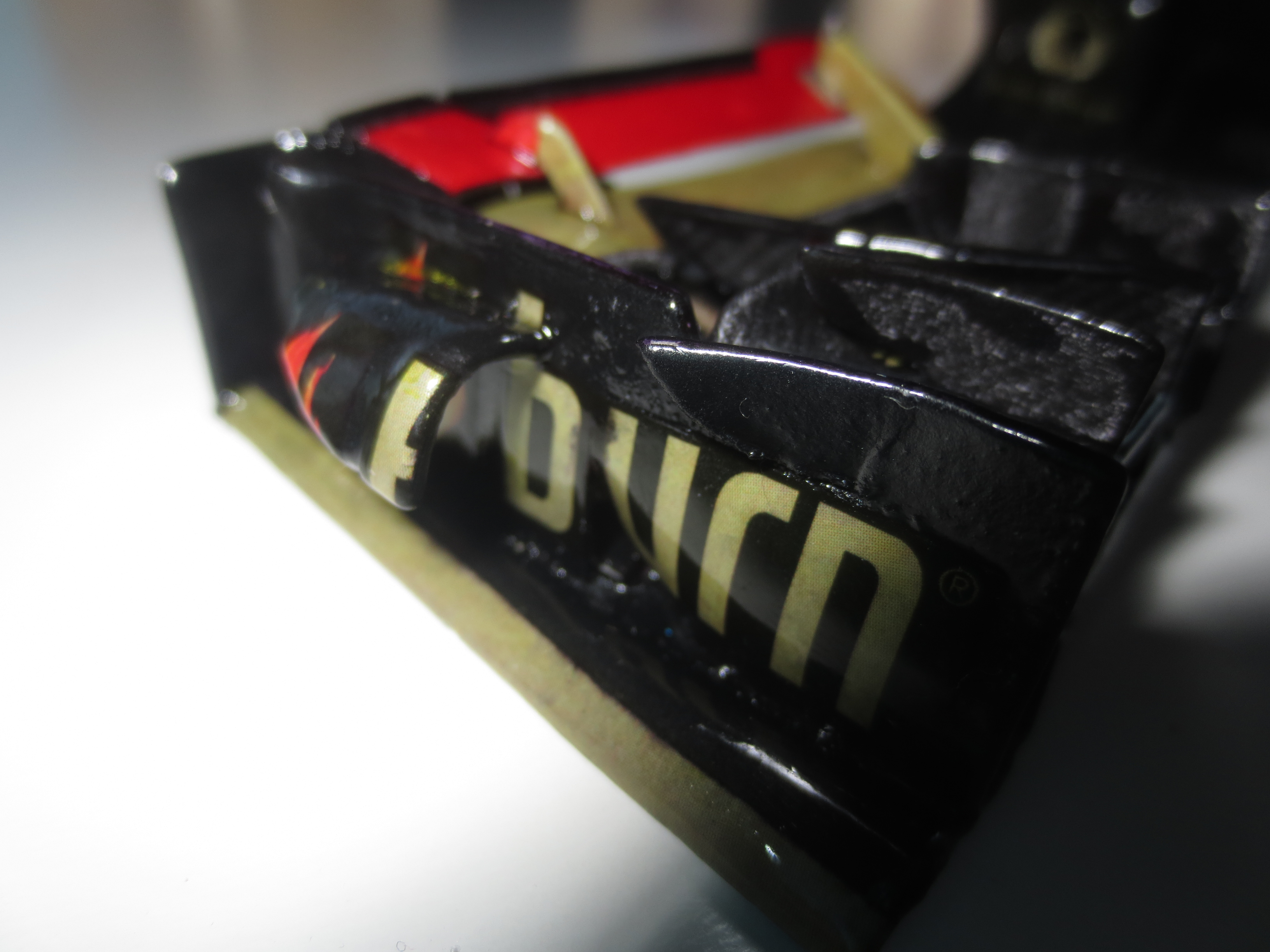
The first flap is bonded to the FWEP. This flaps are a little bit too long in terms of regulations (something around 1mm), so they protrude into the 500mm middle section - looks like Lotus is cheating (I can't be wrong, can I?). :p
Image

These small flaps are good fun to do. Very simple shapes, but they are looking pretty nice. These flaps are also varying a very lot from team to team. The Lotus ones have already nothing to do with the RB ones.
Image

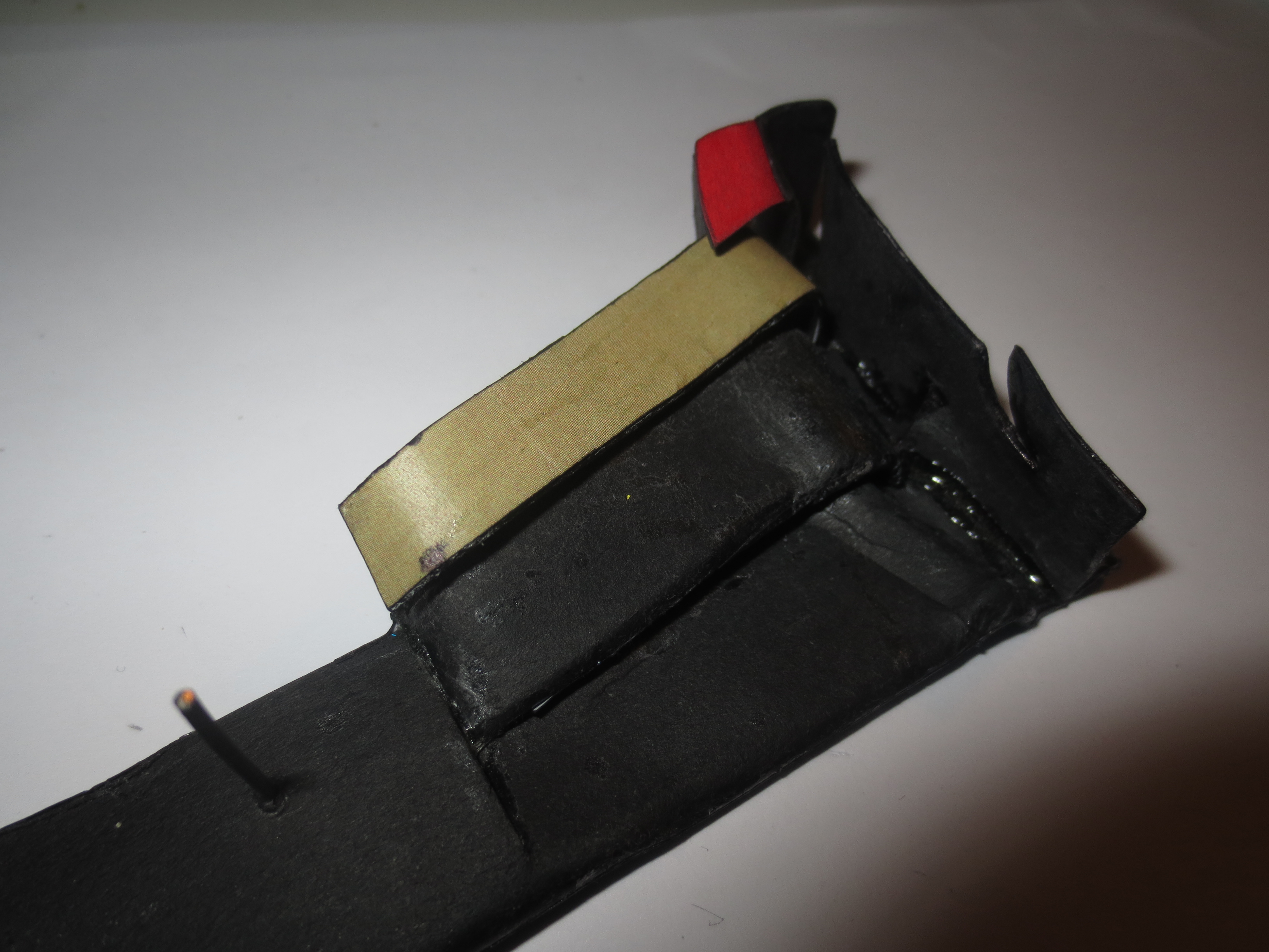
Here you can see the flap adjuster where you can quickly adjust the wing in the box or even during a pit stop. Beside the DRS flap, this is the simplest thing on the car to change aero balance.
Image

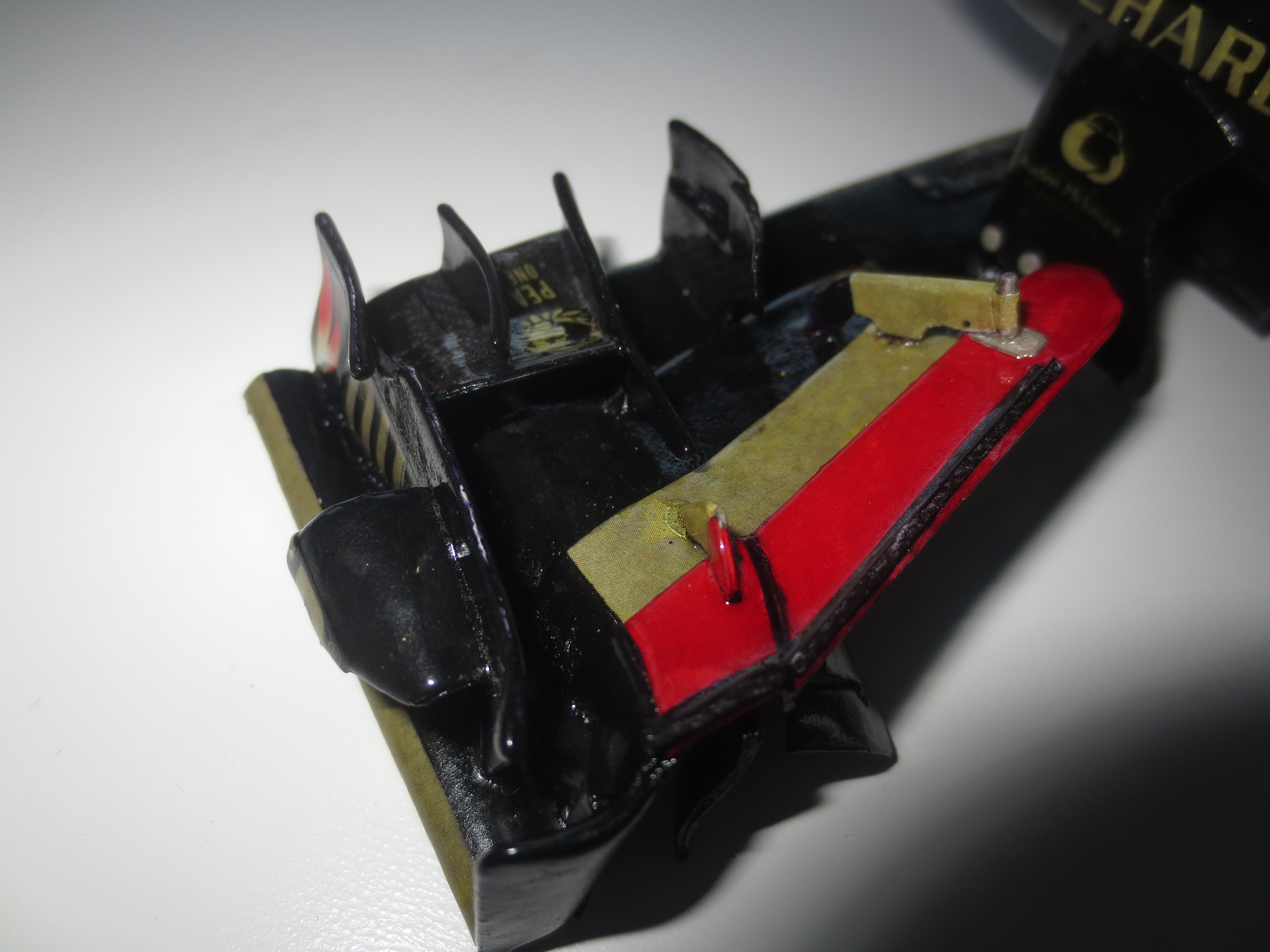
The outboard flap hanger which secures, that the slot gap between the single flaps stays almost constant. On this pic, you can also see the gurneys pretty good. Design gurneys for a real car isn't very exciting and it's pretty much --- when you have to do it in 1:10 scale. But if you're designing a wing, it happens that you also have to design the gurneys.
Image

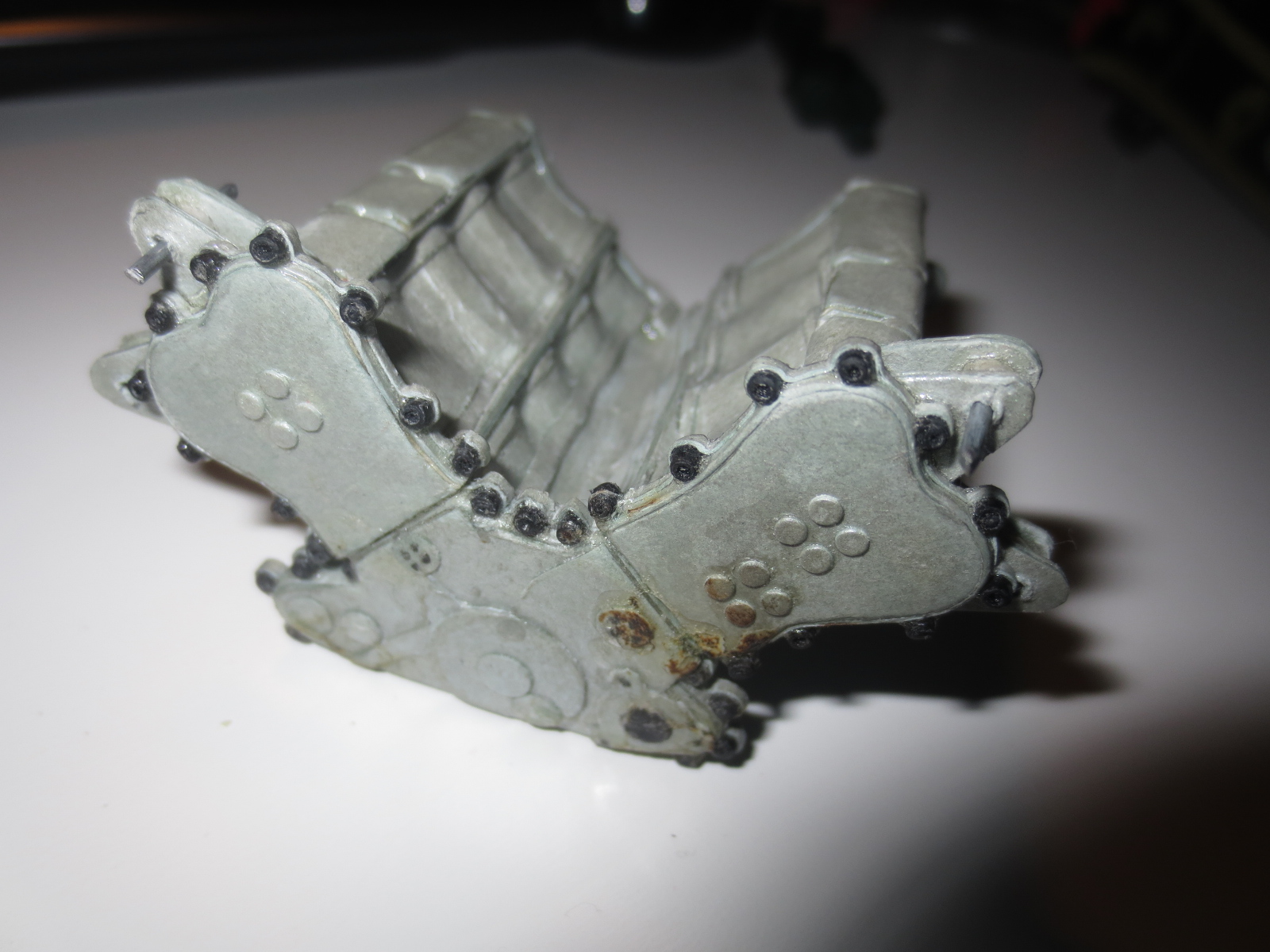
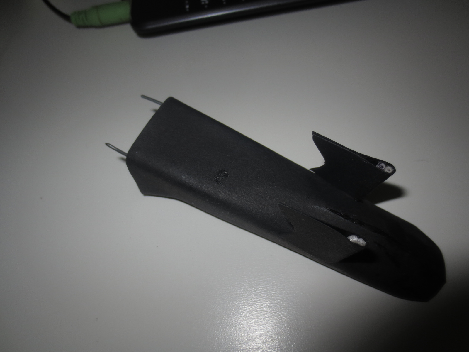
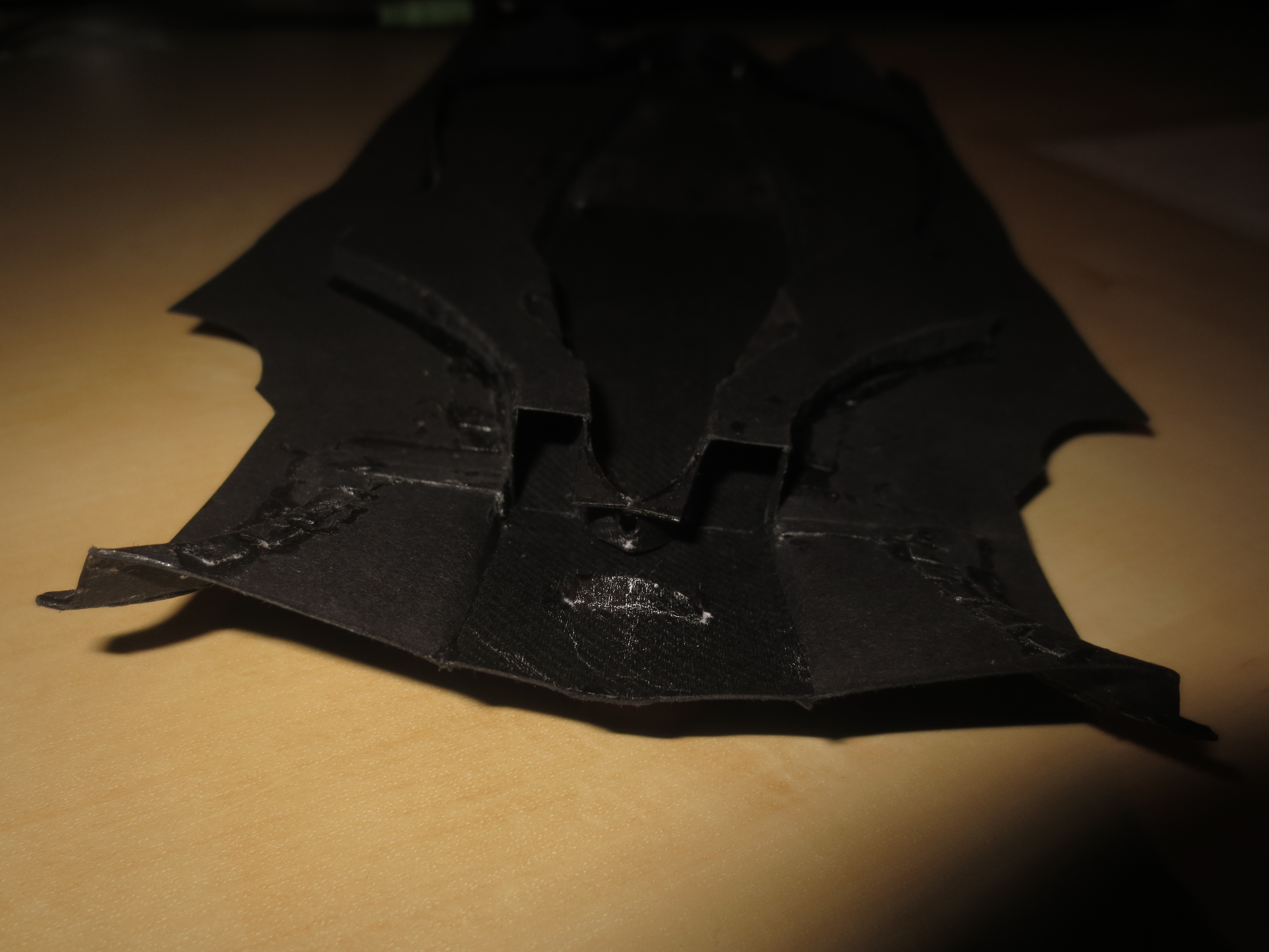
The underside of the full assembly. Notice the very funky swept inboard strakes. Also noticeable is the trailing edge of the FWEP which ends up being 90° to the X-Axis.
Image

The front wing deflection test. The wing wasn't even bonded to the nose that time. As stated above, I haven't measured the deflection. But more than 500g load, which is equal to about 0.33Nm at the pylon mounting point, is pretty impressive for a paperwing. Next evolution of Boeing and Airbus will the the invention of cardboard wing flaps. ;)
Image

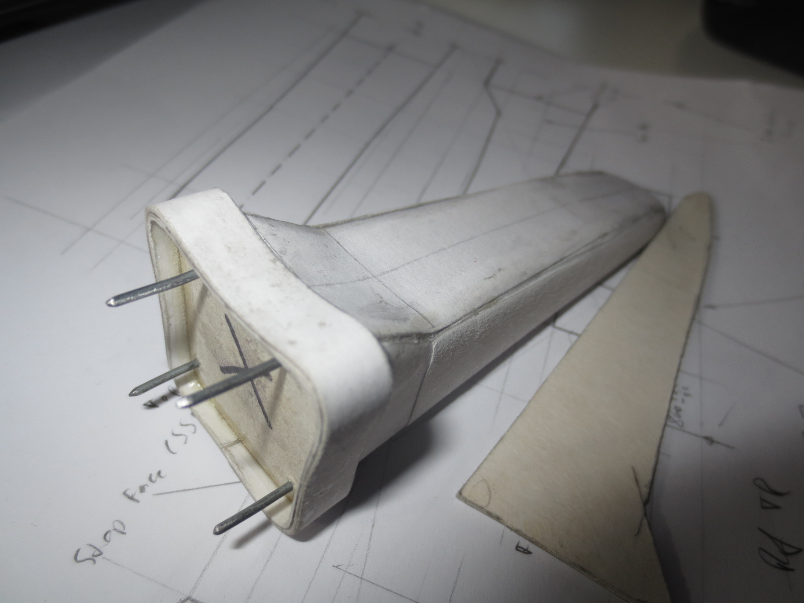
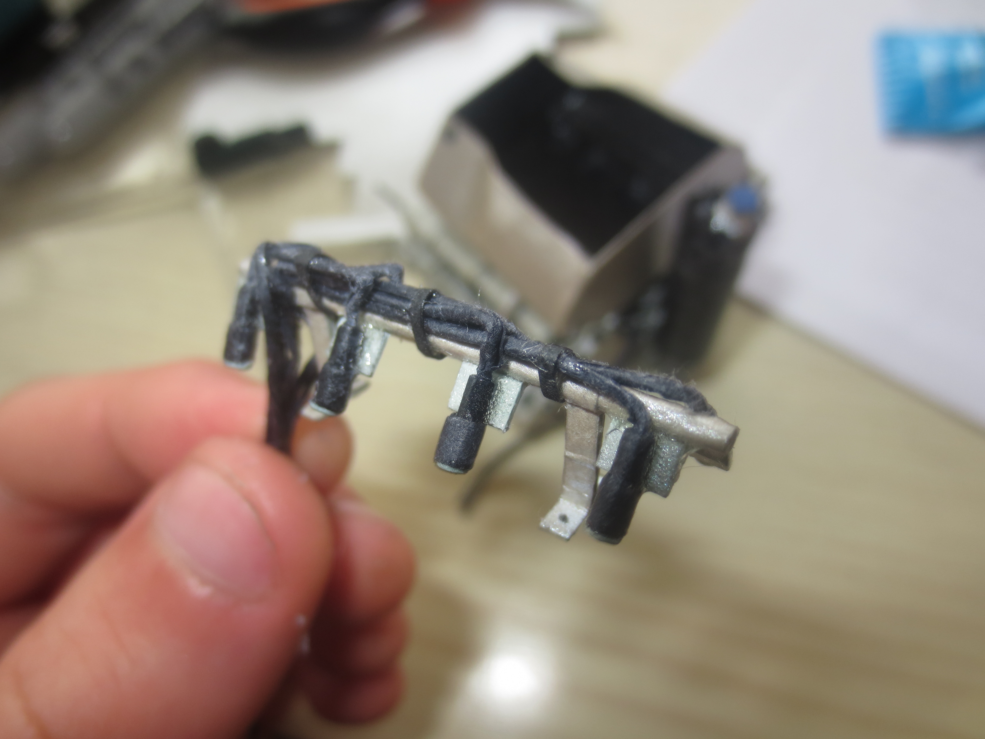
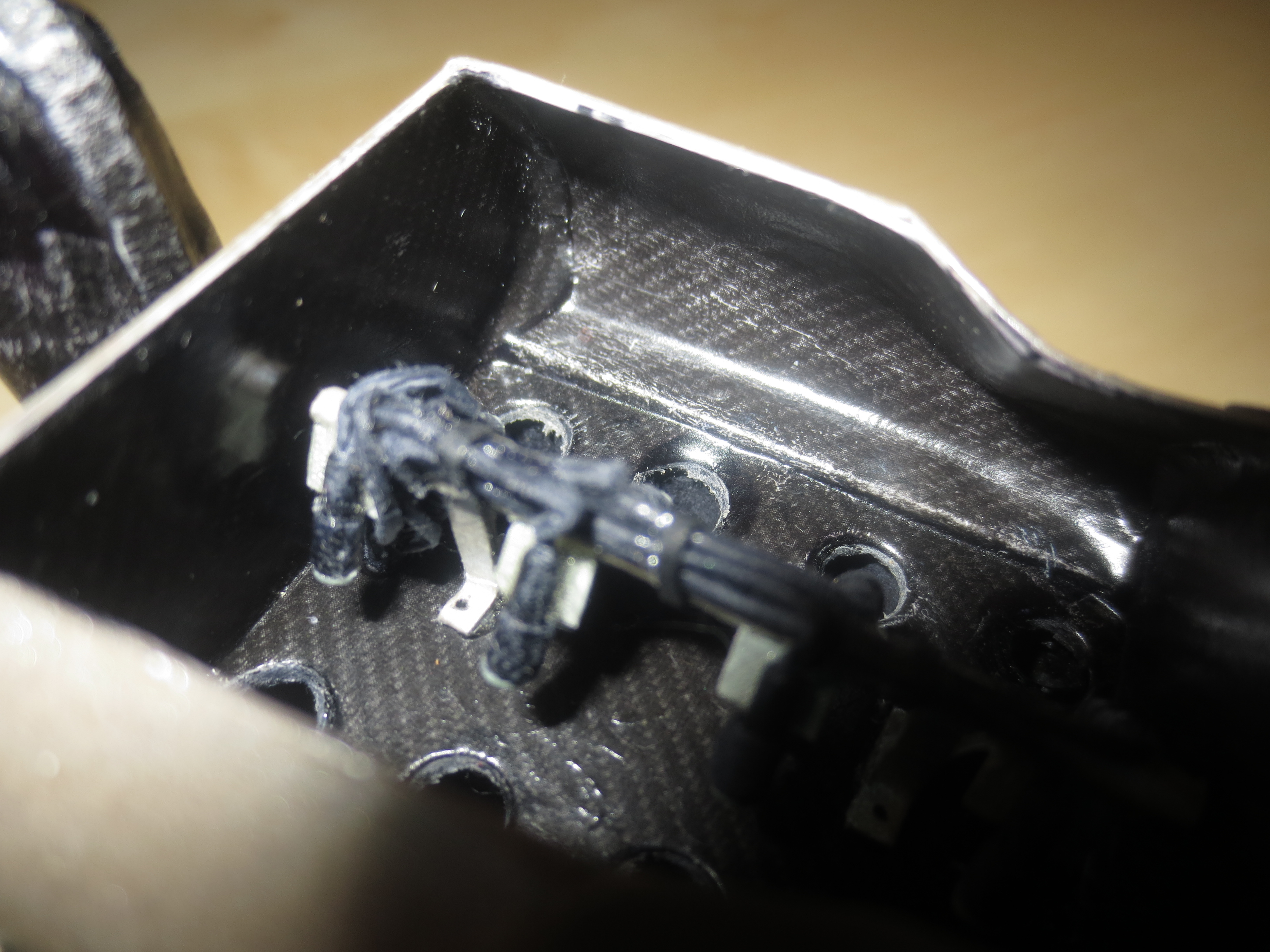
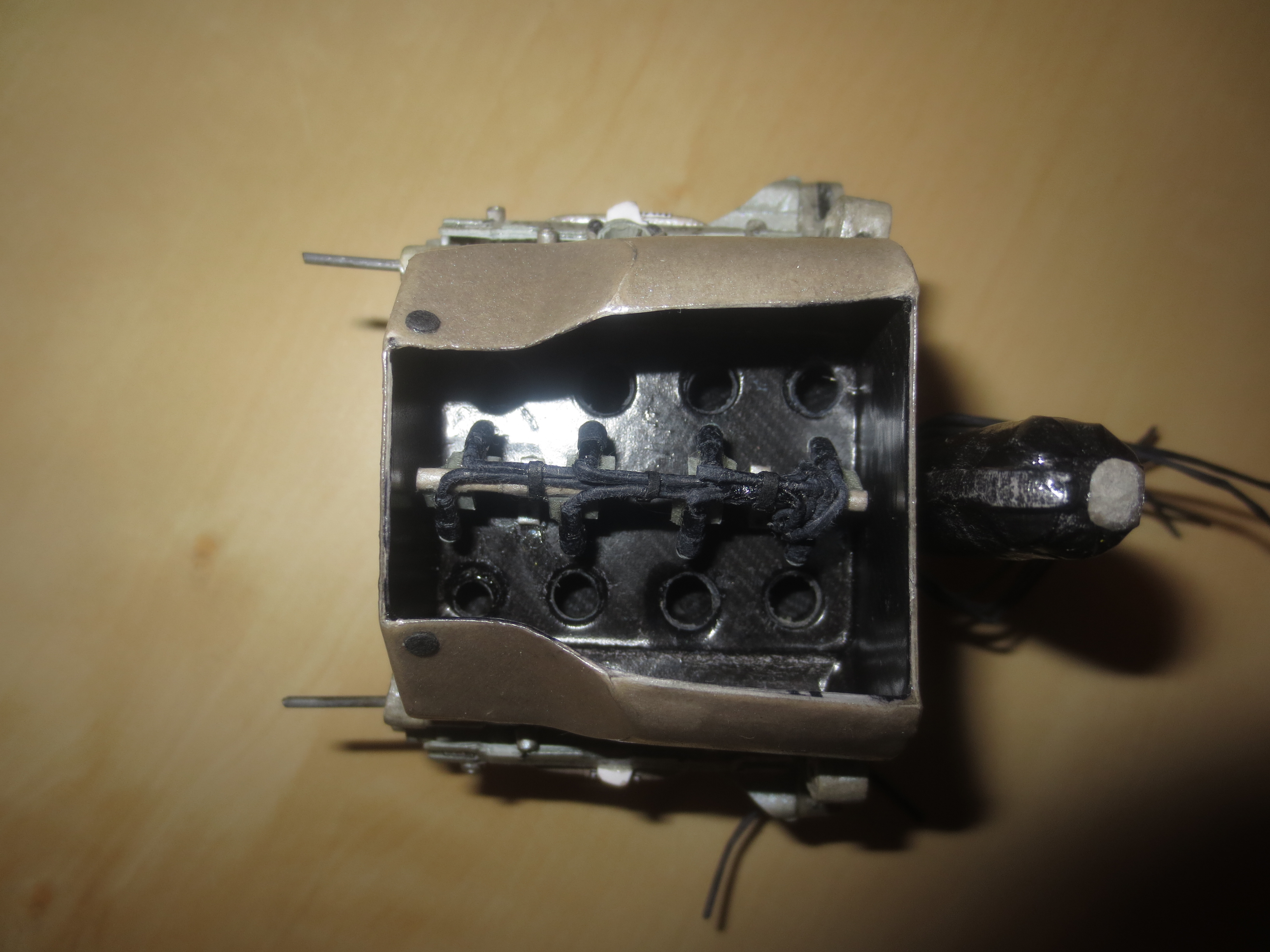
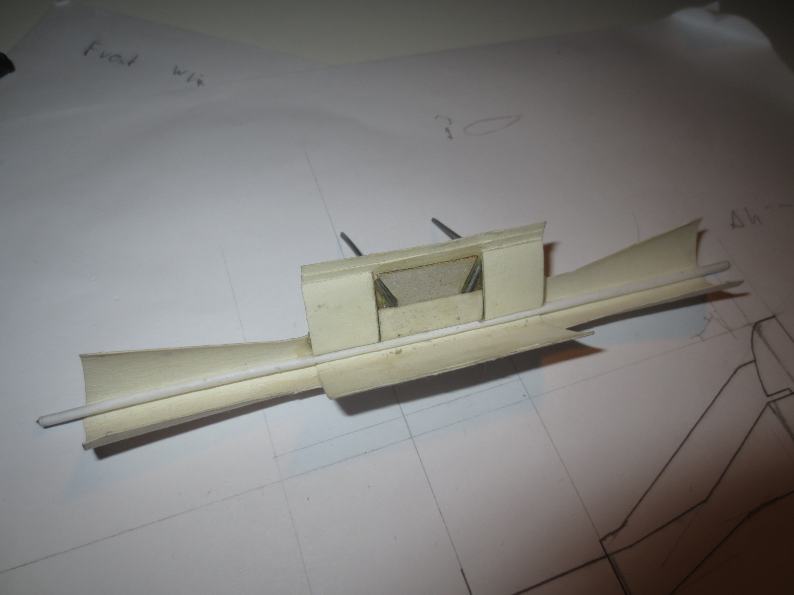
A look inside of the nose. The Nose Pins are pretty long. I will probably shorten them when the car is finished.
Image

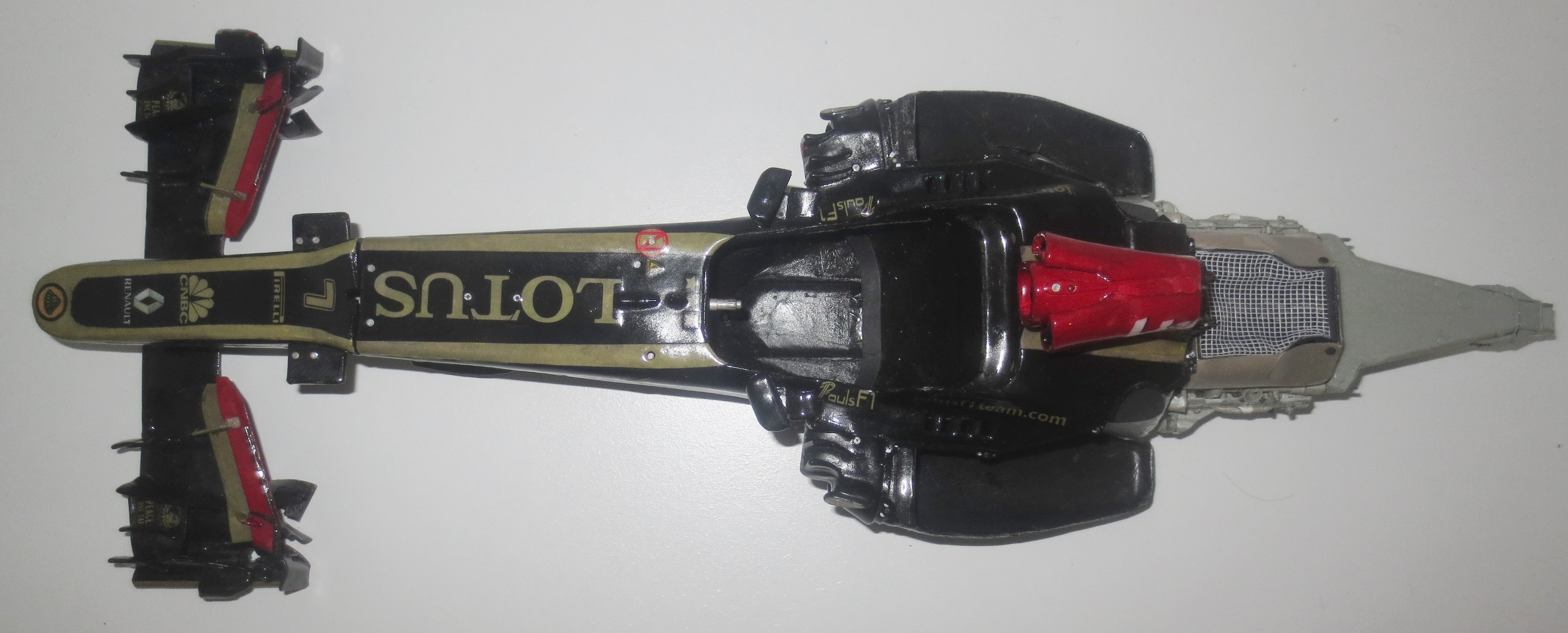
A Top front view onto the outer Front Wing. It's just a masterpiece of aerodynamic art. As I'm no aerodynamicist, I'm always impressed about the creativity of the F1 aero engineers.
Image

Top rear view onto the outer Front Wing.
Image

A few years ago, the Front Wing End Plates were just sipmle flat plates which only had to close off the wing. It's obvious and visible that that's not the only task for them nowadays.
Image

The underside of the outer Front Wing. At the outer few mm you can see the glass fibre which is required by the regulations. At the very front outer edge you can also see a skid block, probably from Ti, to safe the wing from damage caused by grounding.
Image

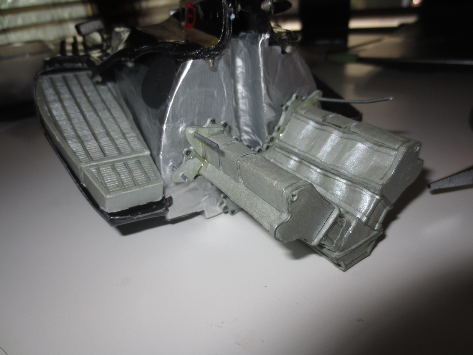
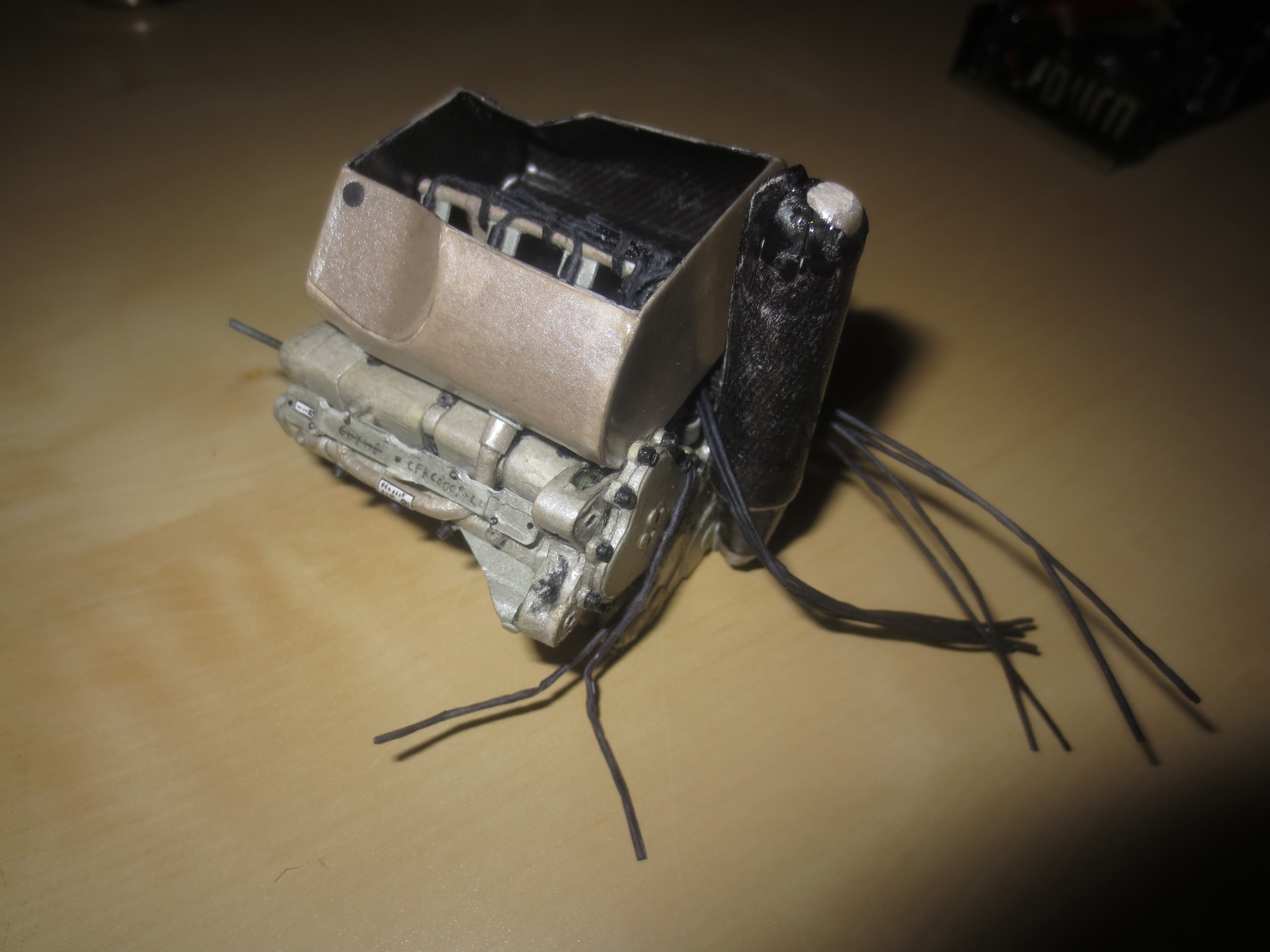
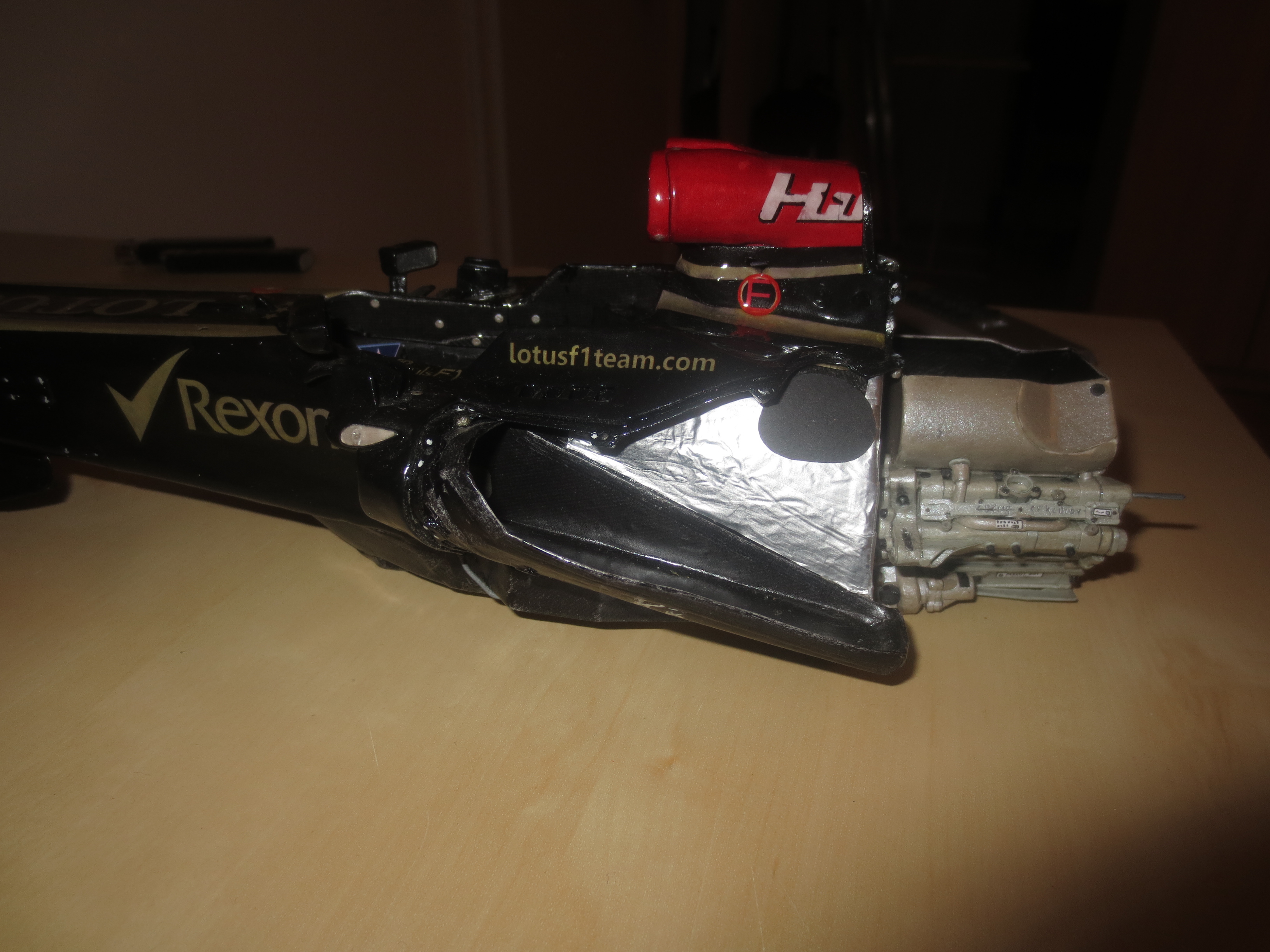
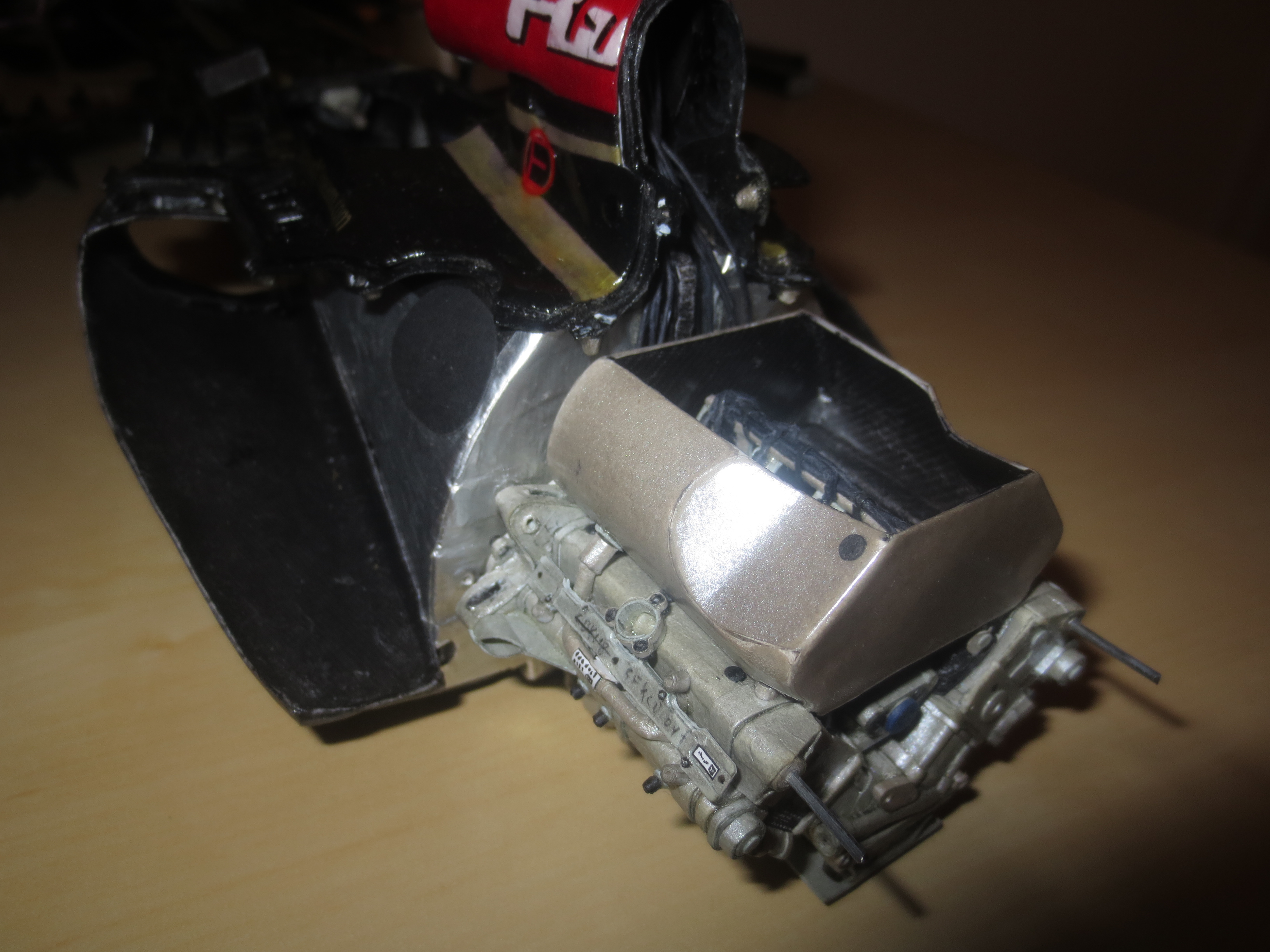
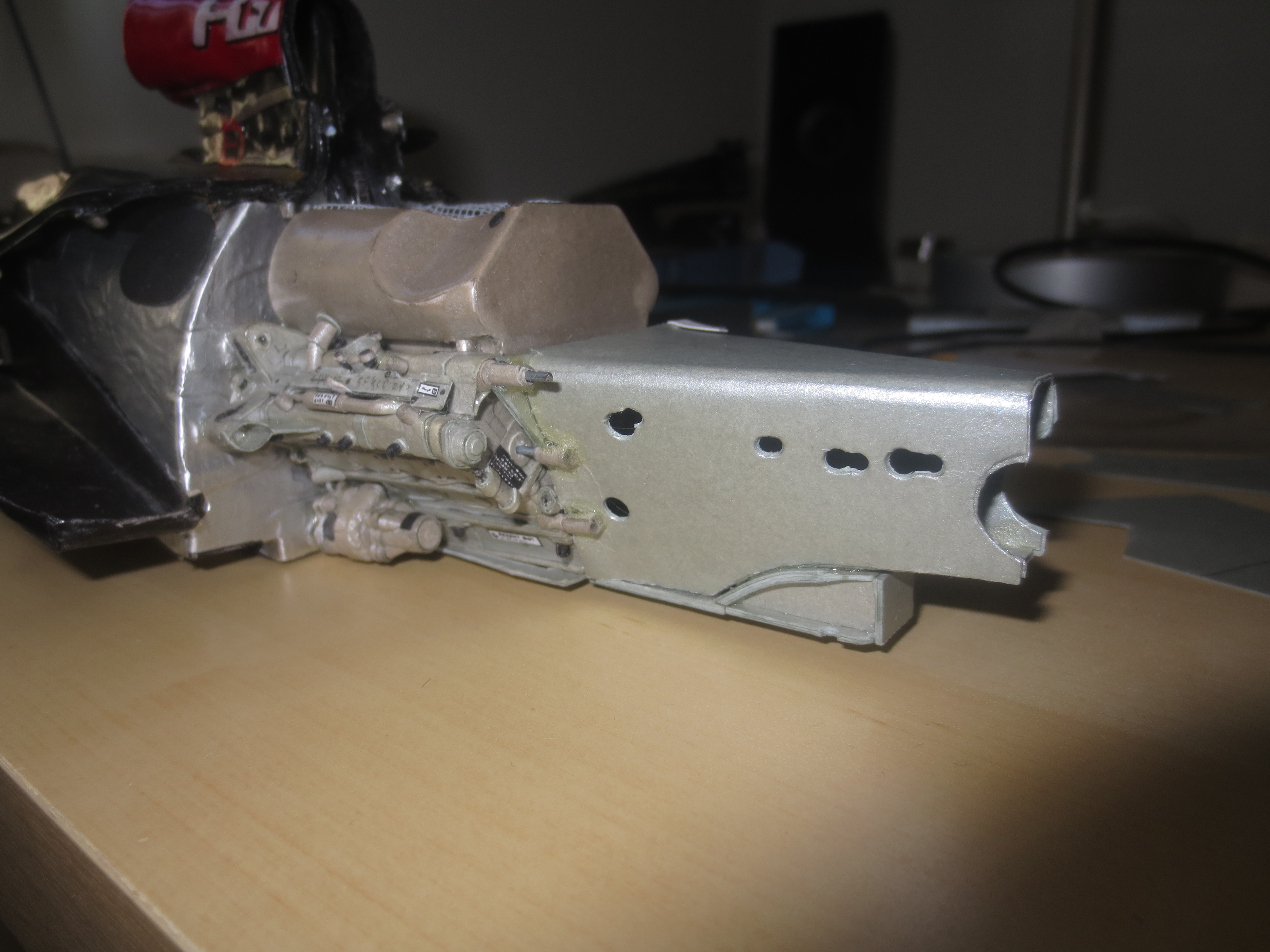
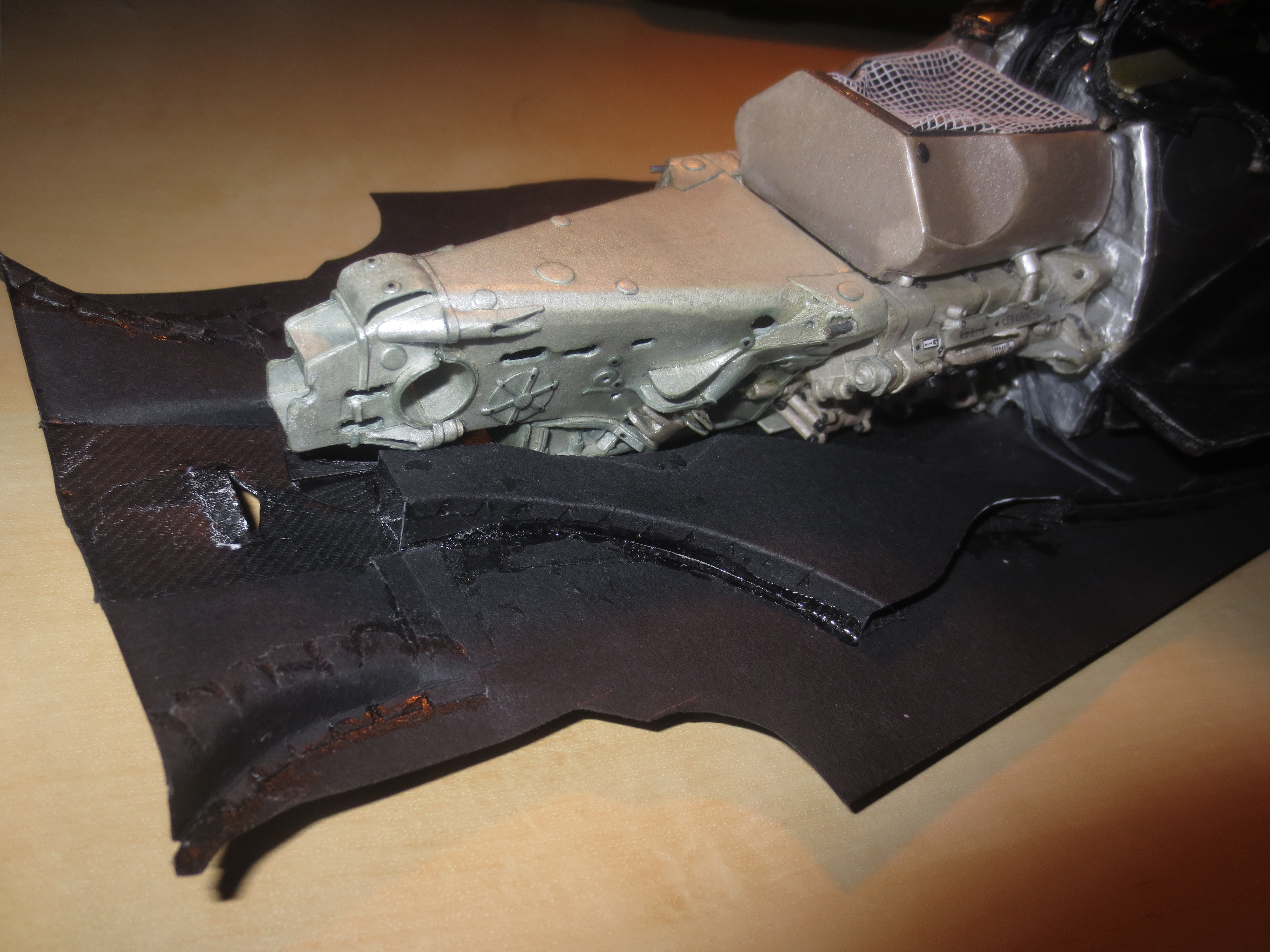
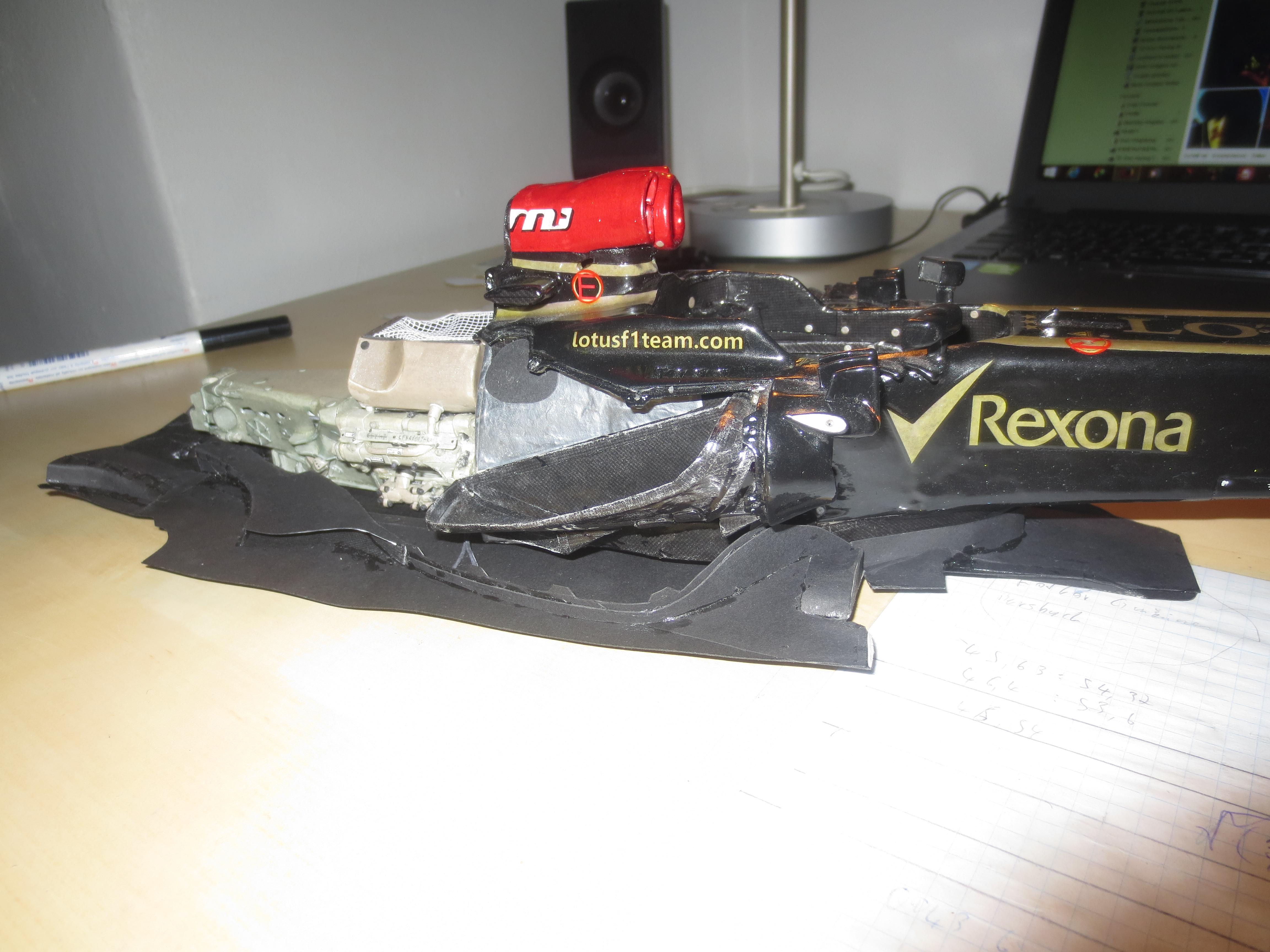
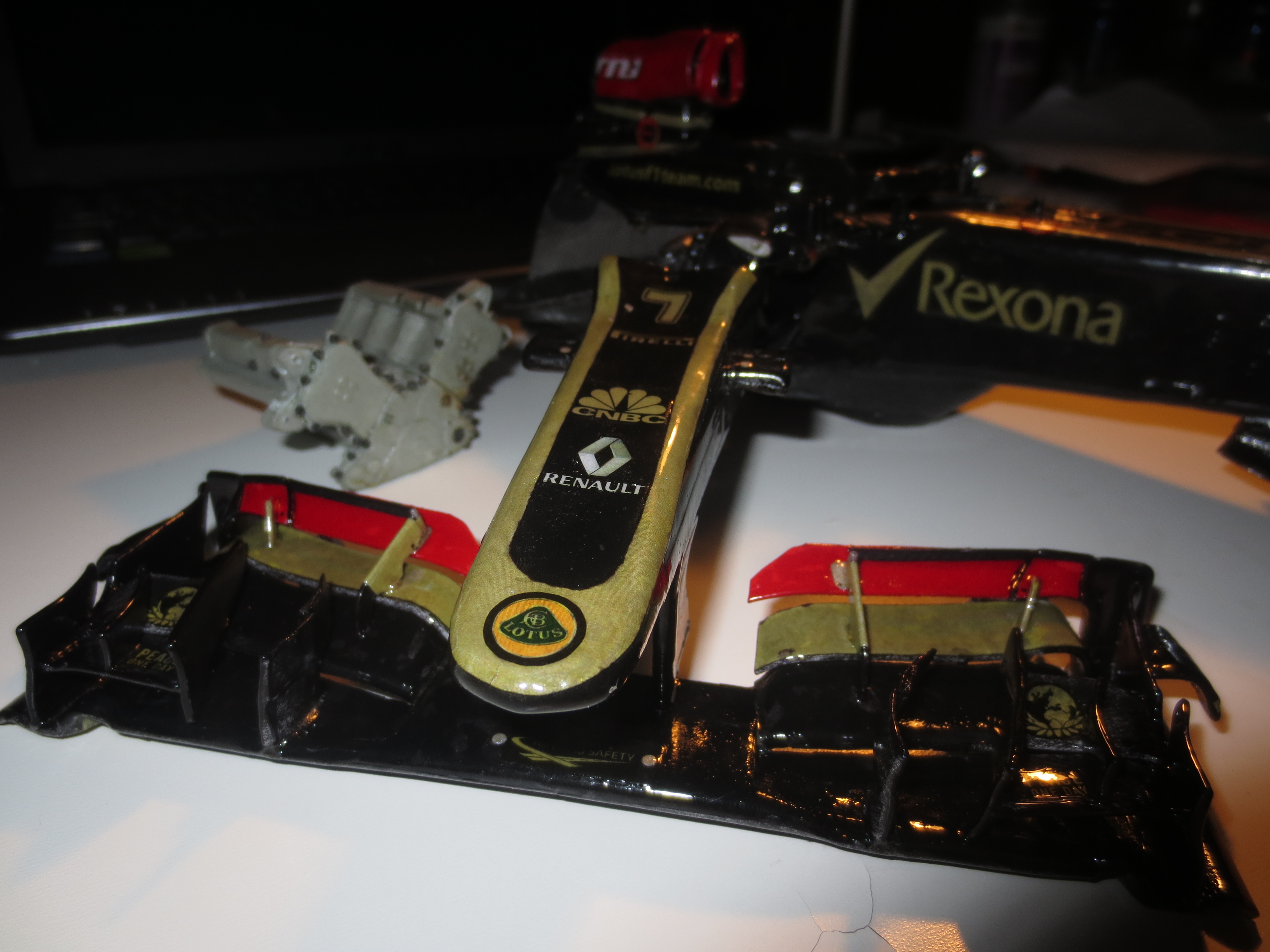
Nose assembled to the chassis.
Image

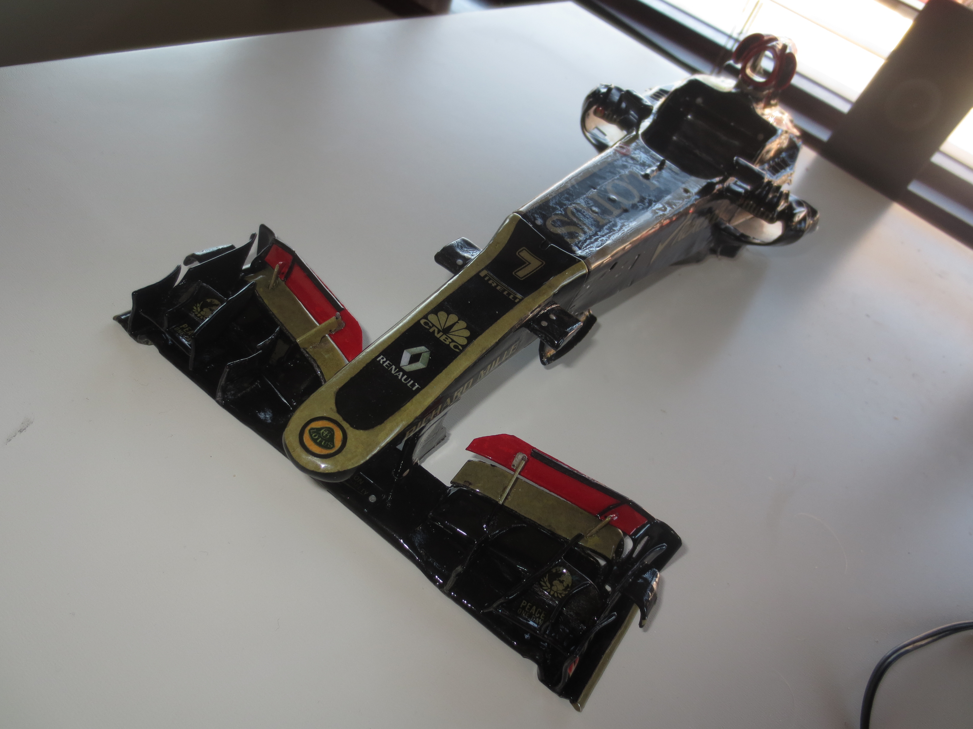
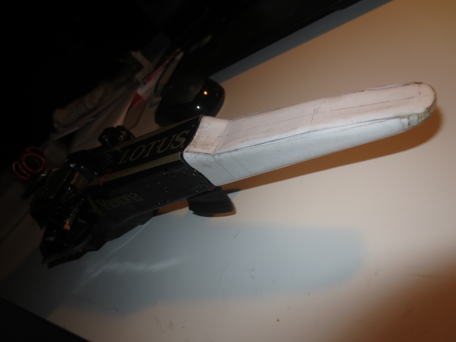
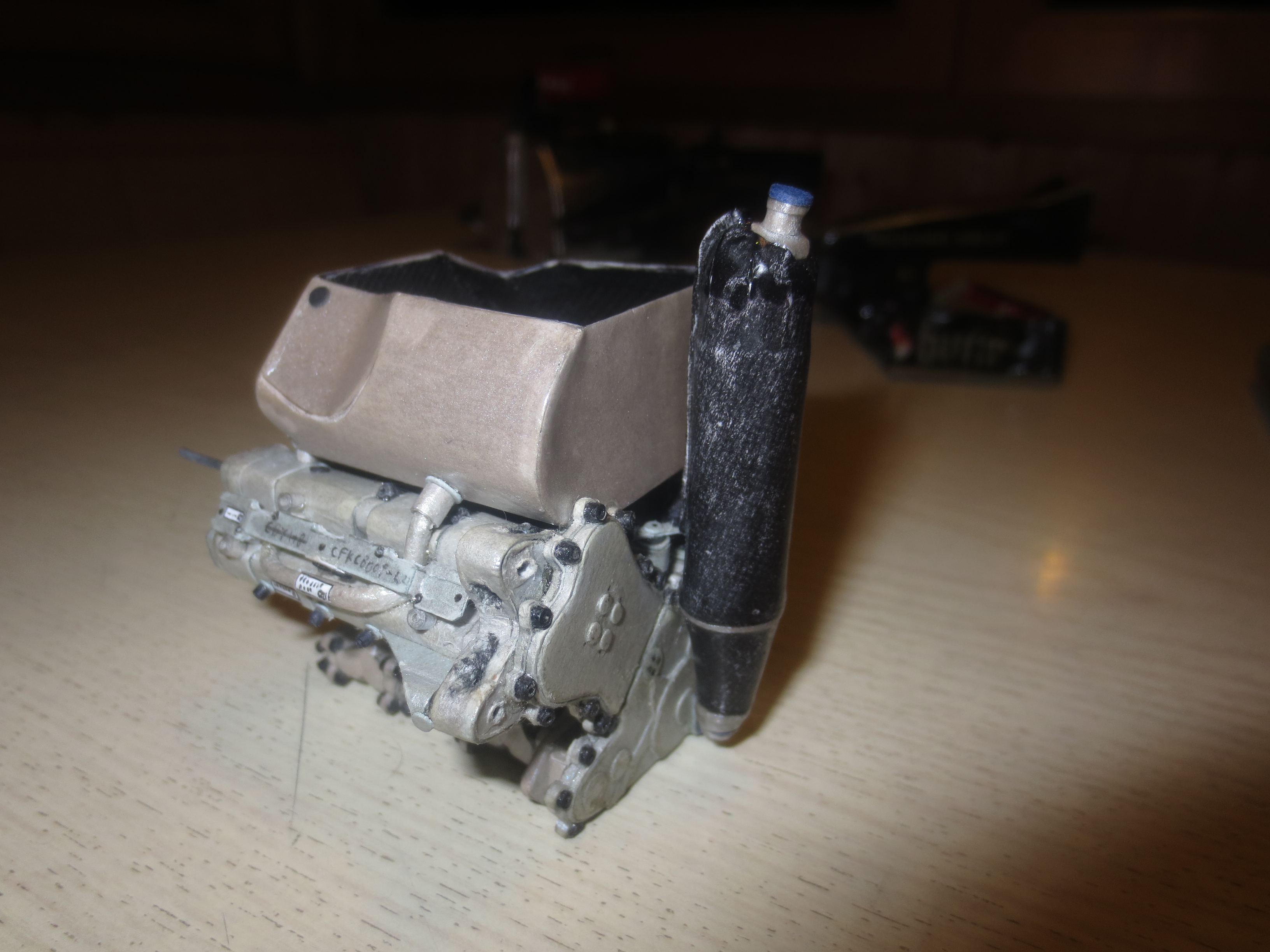
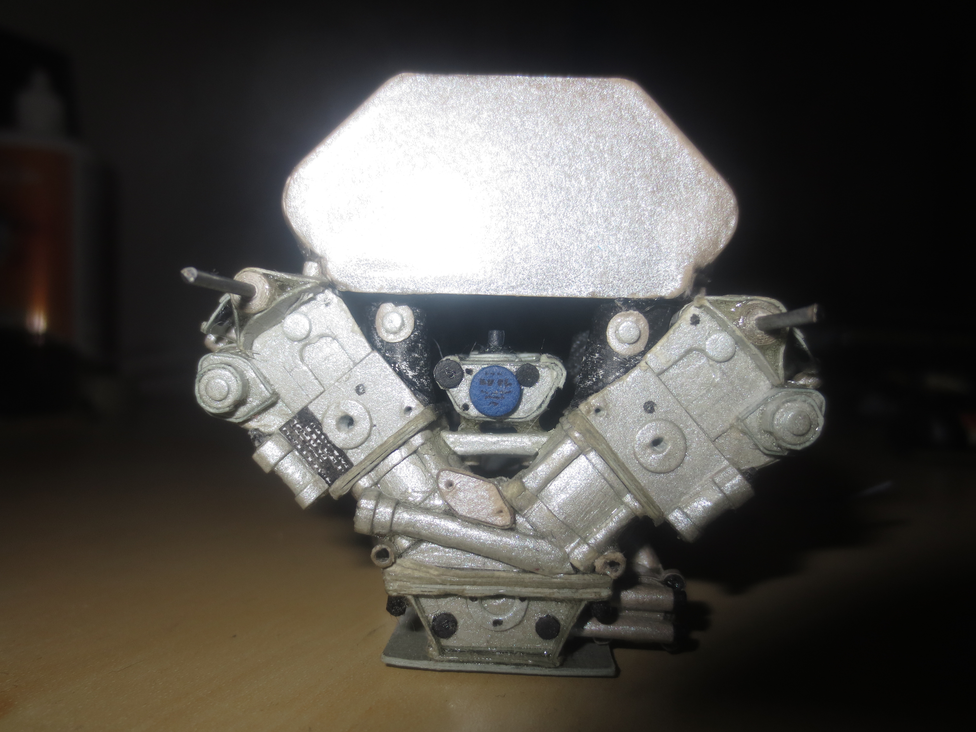
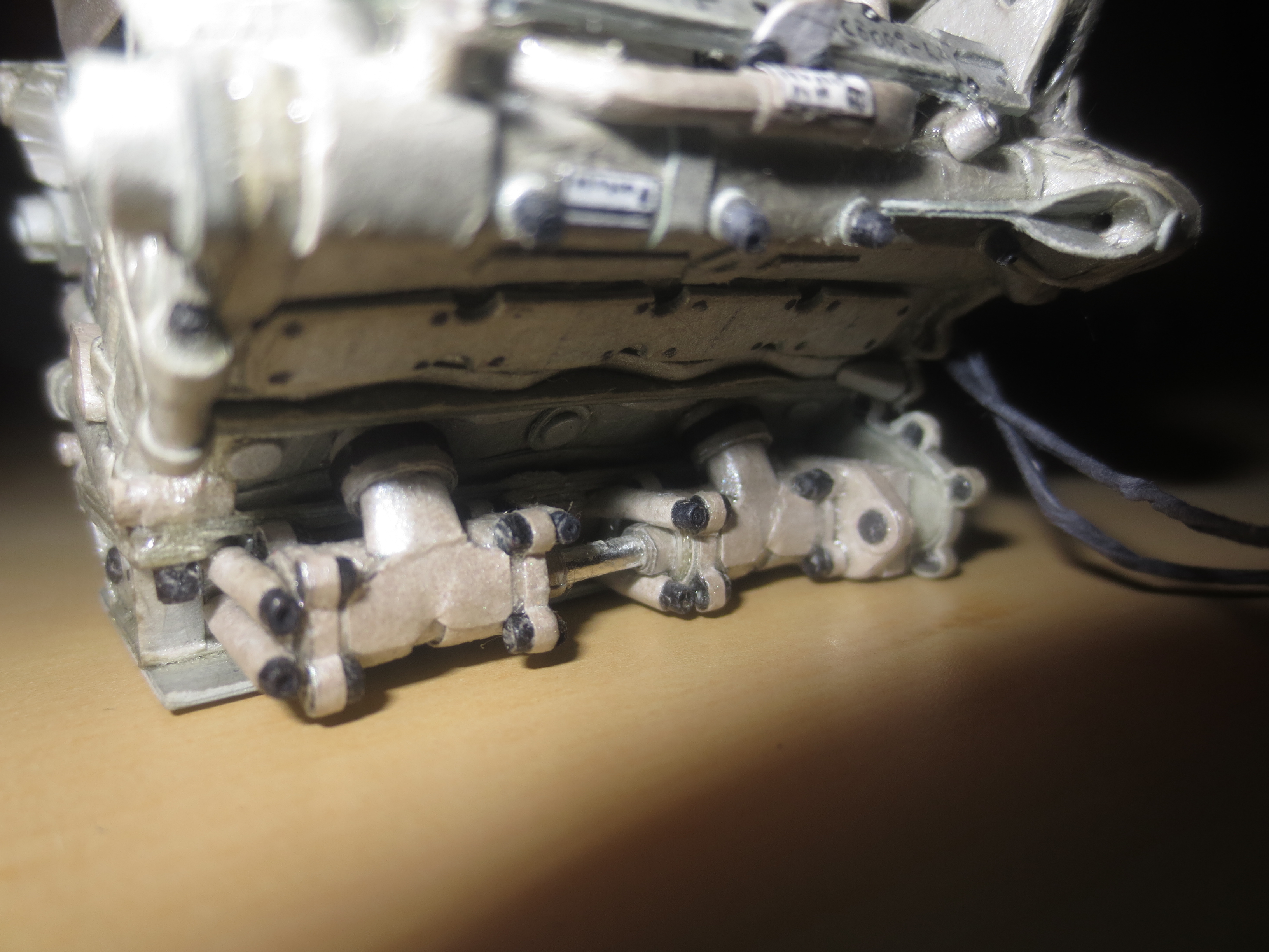
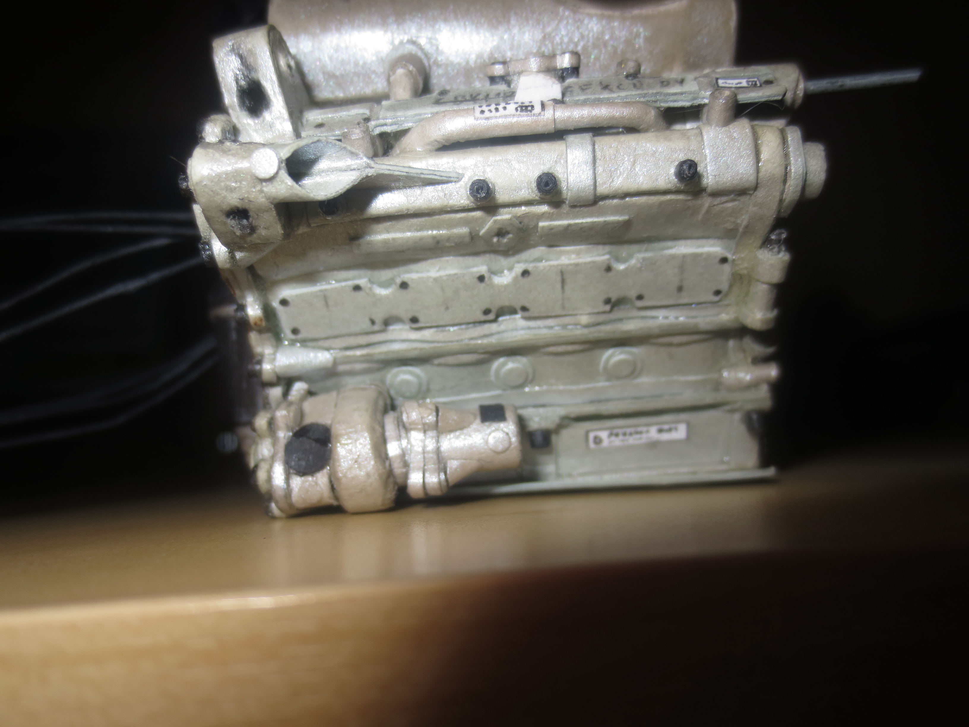
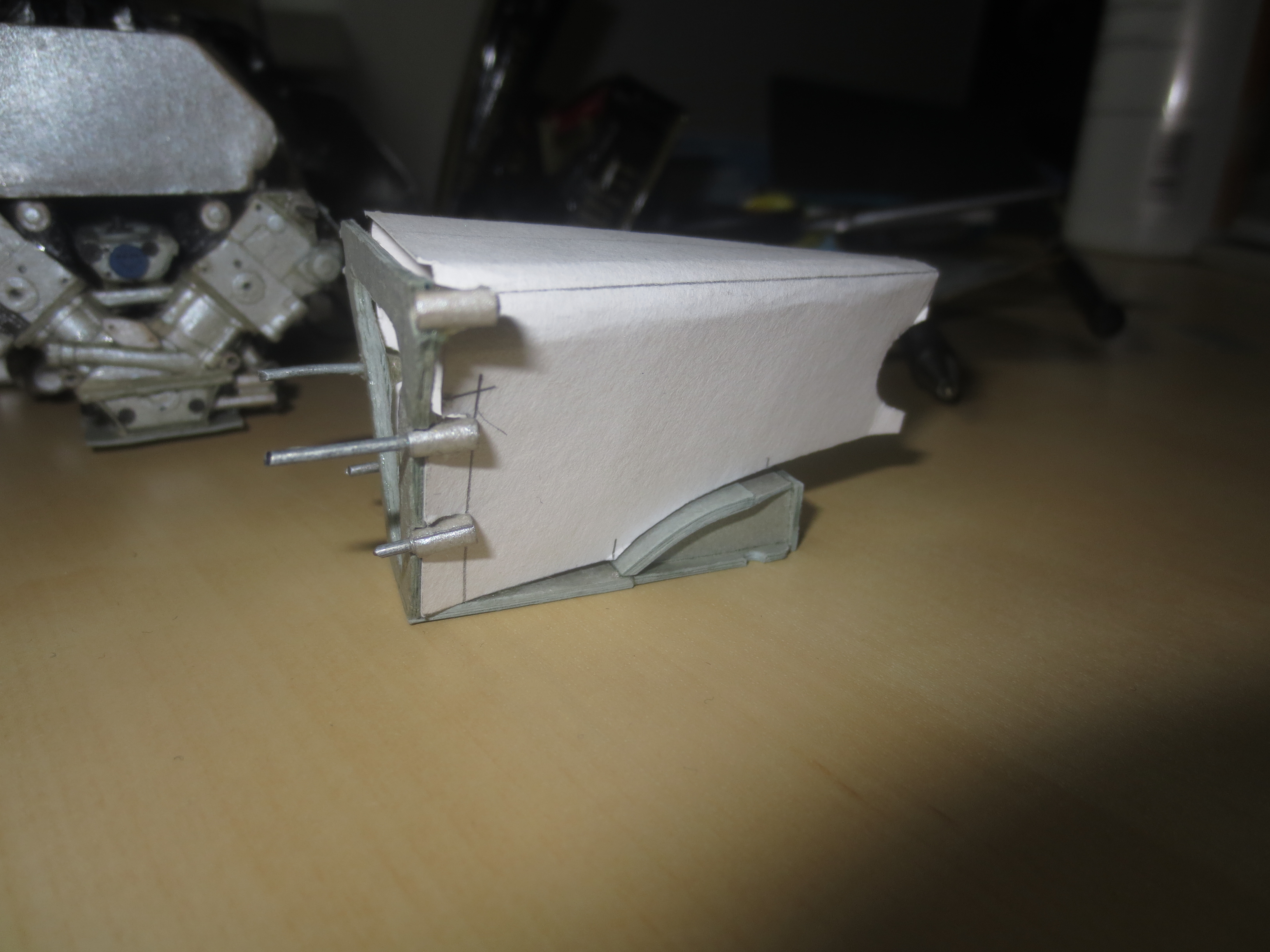
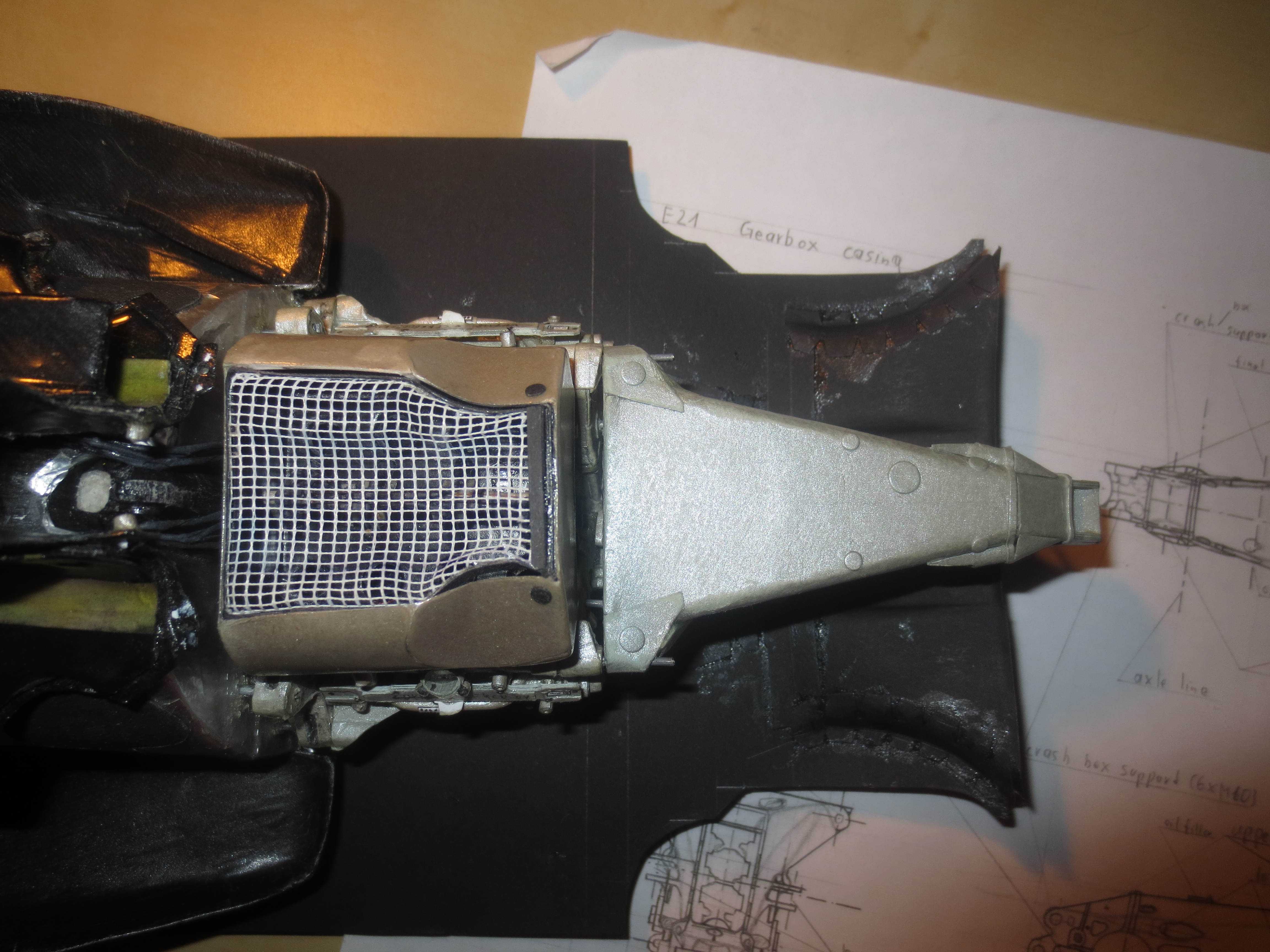
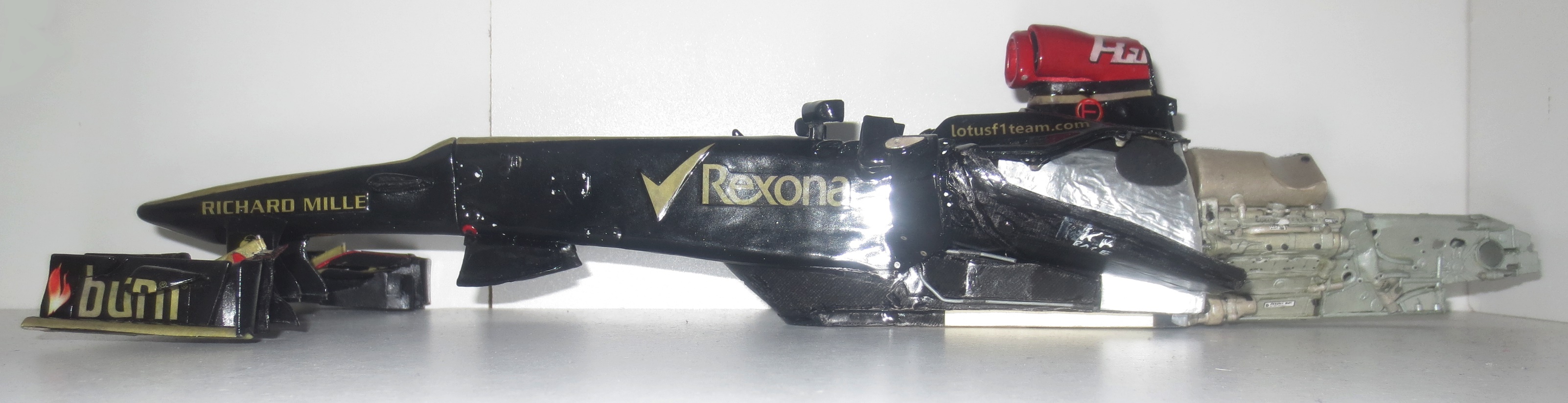
Front Wing in front of the Monocoque and the engine block.
Image

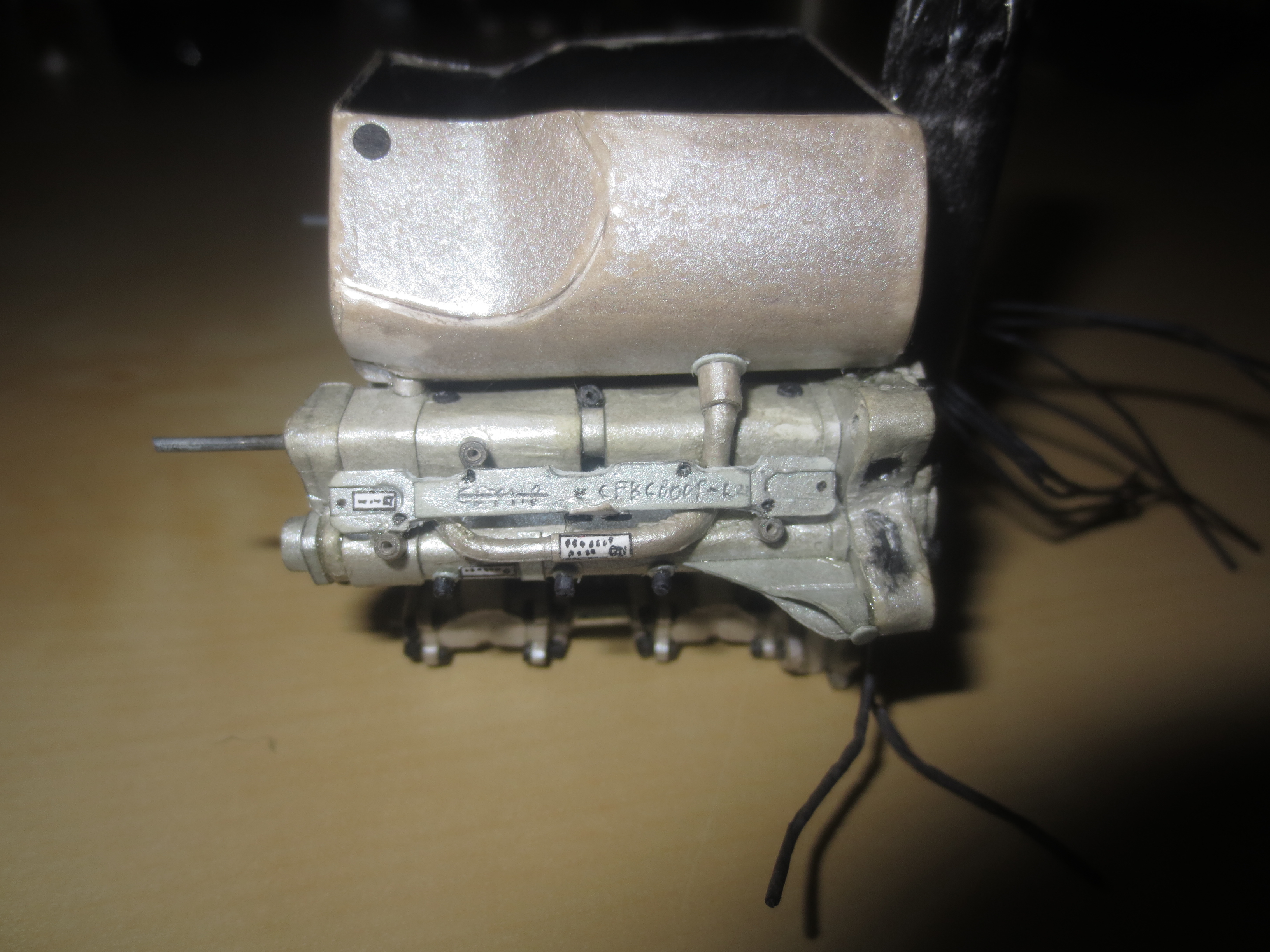
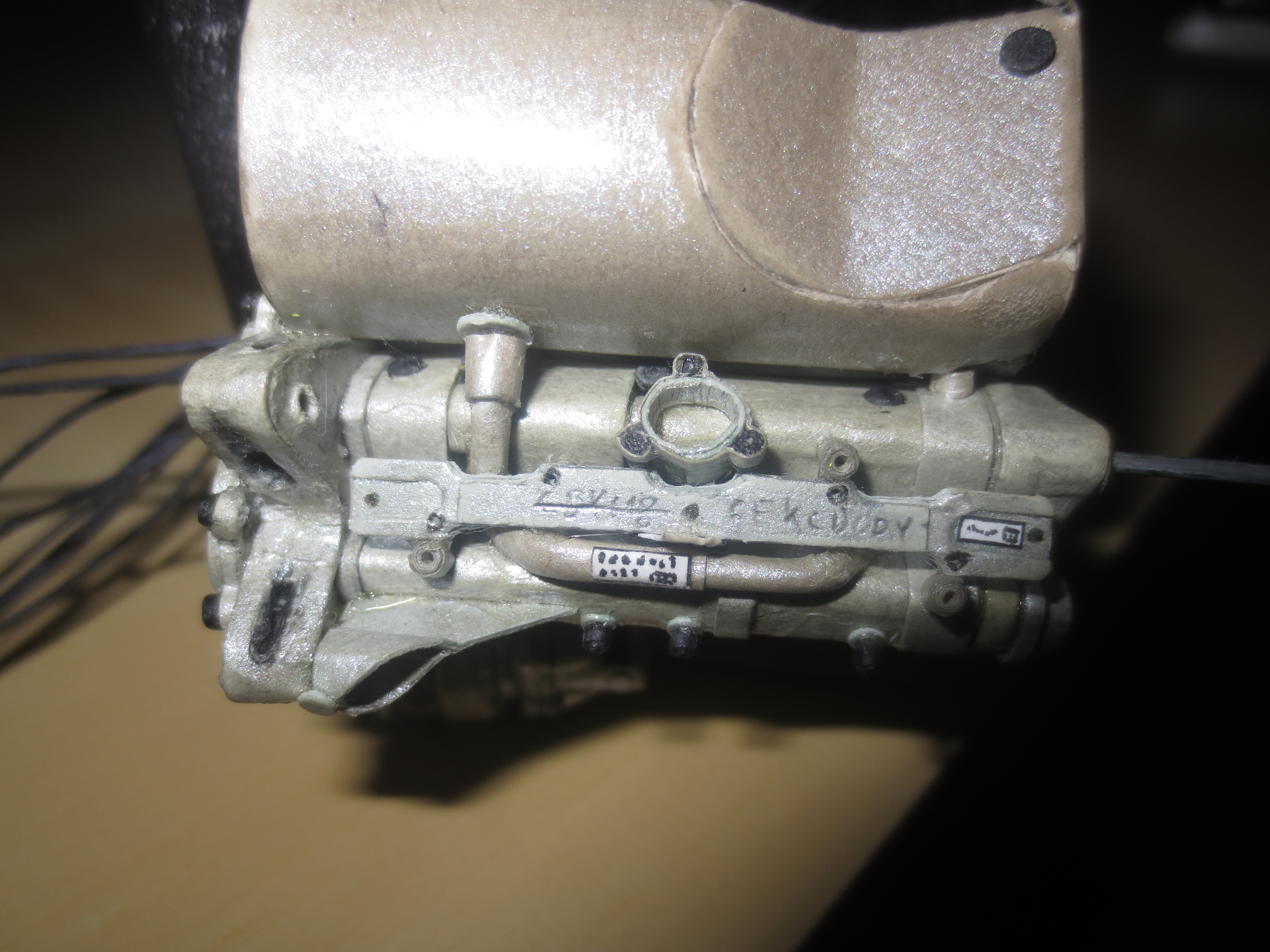
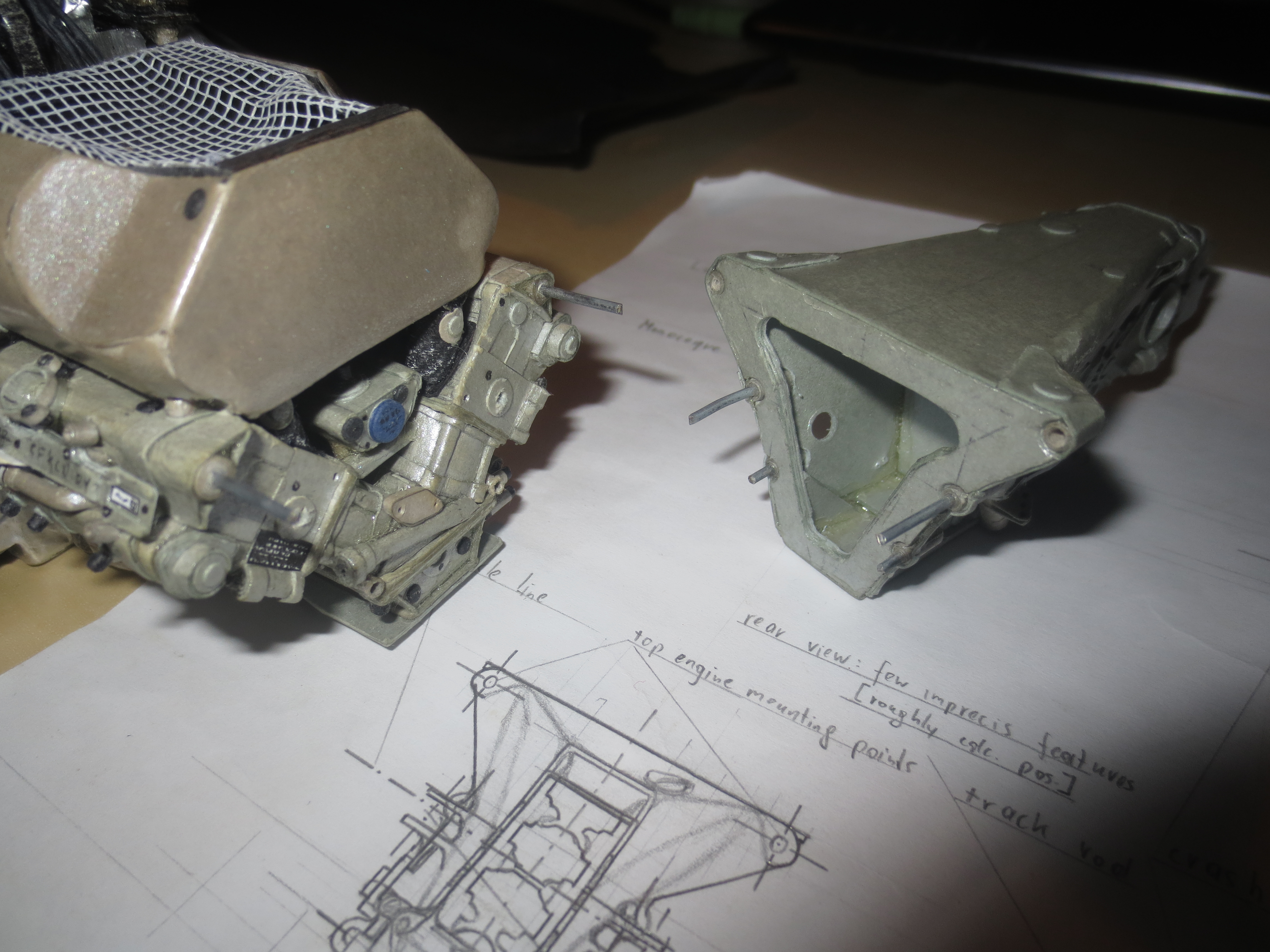
That was pretty much it. There are still 2 layers of lacquer missing, which will be done during engine manufacturing. Now I already revealed what's up next. Yeah, It's the Renault engine.
Image

That's it for now, I hope it won't take that long to the next update.

Cheers,
Paul
"Being second is to be the first of the ones who lose!" - Ayrton Senna

Paul Bischof
Milton Keynes, UK
MK2 2HL
http://paulsf1.wordpress.com/

Schifty
-1
Joined: 04 Dec 2013, 18:54

Re: A paperboard Lotus E21

Post

Paul no... i saw no one of you finish job... here or on your website... no complete picture job is posted...


User avatar
PaulB
72
Joined: 17 Oct 2010, 09:52
Location: Graz/Austria
Contact:

Re: A paperboard Lotus E21

Post

Hi chaps!
Schifty wrote:Paul no... i saw no one of you finish job... here or on your website... no complete picture job is posted...
There are loads of pictures of my finished Red Bull. Either on my blog or Facebook page. Just have a closer look. :)

And again a bit of time passed by since my last update. But now I'm on again and have finished the engine of my Lotus. Just the fitting bolts to the chassis are missing. The engine has something around 700 parts in its final stage.

The engine is much more detailed then the one at the RB7. As you might know, the Lotus E21 and the Red Bull RB7 have the same engines with just a few minor visible improvements. At the RB7 I haven't built a throttle hydraulic unit or the injection system was much more trivial. Also the engine block as well as the pick-up points for the monocoque and the gearbox should be a bit more stiff and rigid. All in all, an expected overall improvement of the engine.

Image
The Renault RS27 engine in its current state, viewed from the right front. You can see the carbon fibre moulded oil tank very well. There is a cutout in the rear wall of the monocoque to accommodate the oil tank between the chassis (fuel tank) and the engine. The oil itself is cooled by the radiator in the rh side pod (temp. approx 90°C - 95°C).

Image
The part of the injection system which is located within the engine manifold. You can see the frame where the injectors sit on which inject the fuel under a pressure of 100bar into the inlet cones. The current 2014 F1 engines have direct injection with a pressure of 500bar. Direct injection saves fuel compared to a conventional injection system.

Image
A view into the engine manifold with mounted injection system. I took some design borrowings for the injectors from older Renault engines as there were no pictures available from the RS27. On a YouTube video, published by Renault Sports F1, you can see a few bits of the system of the 2011 engine (on the test bench).

Image
During the transportation back to Graz, the oil filler came off the oiltank (top of the tank). I'll redo it before fitting the engine to the car. The two lines you can see coming from the inside of the V to the rh side of the engine are for the throttle control and will lead into the ECU (Engine Control Unit).

Image
The RS27 engine from the top. The inlet manifold, which is fed by the airbox, is a CFRP item with a heat protection layer on the outside to prevent the air for the combustion process getting hot due to the engine/radiator heat.

Image
Cam(shaft) cover at the rh side. I'm not 100% sure what this line is for, which leads into the manifold. But I expect it to be the supply for the pneumatic valves. Even if they should work passively, I'm sure, there are some losses during a race and you have to refill the chambers of the valves.

Image
Lh side cam cover. Same as the rh one, just with the additional water inlet.

Image
Rear view of the engine. You can see a part of the hydraulic throttle system. The two hyd connectors which supply the unit are missing. You can see also the two upper bolts to fit the gearbox. The four other bolts (which are required by the regulations) will probably be fixed to the gearbox.

Image
Rh side of the engine with the oil pumps being visible at the bottom of the engine. There will also be the hydraulic pump of the rh side of the engine beside the oil pumps. But I will not mount it before fitted the gearbox as I think, the hyds pump is fixed to the gearbox.

Image
Lh side of the engine. You can see the water pump (front) and the alternator (back). I'll have to replace the alternator with a MGU I guess.

Image
The Renault RS27 pre assembled to the chassis. Again you can see how small such an engine is. The dimensions length x with x height are 49.8mm x 71.7mm x 54.1mm.

Image
Renault RS27 with chassis.

That's it for now and I guess you won't have to wait that long agaion for the next update.

Cheers Paul
"Being second is to be the first of the ones who lose!" - Ayrton Senna

Paul Bischof
Milton Keynes, UK
MK2 2HL
http://paulsf1.wordpress.com/

User avatar
PaulB
72
Joined: 17 Oct 2010, 09:52
Location: Graz/Austria
Contact:

Re: A paperboard Lotus E21

Post

Gearbox and Underbody Manufacturing

After finishing the Renault RS27-2013 engine, I started to design the gearbox (my usual process chain: monocoque-engine-gearbox-underbody-systems-suspension-wings-bodywork-wheels). The Lotus' gearbox is a bit of a pain to do as they are one of the last teams, not to use a Carbon composite housing. It's a cast Titanium structure. To rebuild metal structures from paper is always very difficult. Anyway, it's (almost) done and I can be pretty satisfied with it.

The whole suspension stuff is located within the gearbox. That's a trend which appeared about three years ago. Before, most of the suspension stuff (dampers, springs) was mounted outside the housing beside the gear cluster. With the aero development over the last years, the teams started to locate all this stuff inside the housing in front of the gears, to get a tighter ass. I don't know, if I'll add all this stuff inside the gearbox. I will do the ARB and the drive shaft definitely but I won't do the gears.

This week I also started with the underbody design.

Front bulkhead of the gearbox. The starting point of the design. You can clearly see the six pick up points to mount the gearbox to the engine. At the real car, this is realized by six M12 studs.
Image

First attempt for the basic structure. The shape is pretty trivial. I just needed one try to get it done. Very important is the integration of the studs into the structure. They have to pick up the whole load. It's the first gearbox, where I do it this way. My previous gearboxes were just bonded to the rear face of the engine. The advantage here is a much higher stiffness between the engine and gearbox.
Image

The first try to fit the gearbox to the car. Even without glue, the connection is so stiff, that I can carry the car just by holding it on the gearbox.
Image

Finished gearbox housing mounted to the car and pre fitted underbody.
Image

From the top you can see how tiny the gearbox is. There's loads of space between the wheels and the gearbox for aero tweaks.
Image

Gearbox removed from the engine.
Image

Rh side of the gearbox housing. The hole that you can see at the lower front of the housing is for the ARB. The top front one for adjusting the heave damper. You can also see the angled rocker. At the rear you can see the fixing point for the rear crash structure.
Image

Lh side of the gearbox housing. At the rear below the final drive, the oil pump will be located.
Image

My gearbox drawing. I had to stretch the gearbox by about 3mm compared to the drawing to reach the correct whelbase.
Image

With the gearbox mounted, the cars current length is at 458mm. With the rear crash structure attached it will reach its full length of 508mm.
Image

Top view of the car with mounted gearbox.
Image

Current state of the underbody. There's still a lot of work left to do. Note the blown starter hole in the diffuser area. That's to prohibit a flow separation. More on this later on during the build of the underbody.
Image

That's it of the mo, thx for watching.

Cheers,
Paul
"Being second is to be the first of the ones who lose!" - Ayrton Senna

Paul Bischof
Milton Keynes, UK
MK2 2HL
http://paulsf1.wordpress.com/


User avatar
Alonso Fan
10
Joined: 06 Apr 2013, 18:21

Re: A paperboard Lotus E21

Post

Amazing!
SHR Modding
Youtube
Twitter
Discord

Sound Developer for Reiza Studios
Sound Modder for Assetto Corsa

User avatar
PaulB
72
Joined: 17 Oct 2010, 09:52
Location: Graz/Austria
Contact:

Re: A paperboard Lotus E21

Post

Hi Chaps,

Underbody Manufacturing

With the underbody, I'm working now on (one of) the most important aerodynamic feature(s) of my Lotus. The underbody produces about 30% of the cars (negative) lift, but just a little fraction of its drag. The side of the floor is sealed by vortices, created by the barge boards at the leading edge of the floor.

Special features on the Lotus floor are the Coanda-exhaust sealed diffuser and the blown starter hole.

The Coanda exhaust, was the difference making aero feature in the seasons 2012 and 2013. The Coanda-effect describes the phenomenon of a fluid-flow, following a convex surface instead of separation of it and move along its original flow direction. In Formula 1, this effect was used, to lead the high-energy exhaust plume between the rear tyres and the floor to seal the diffuser. Some teams were able to control this tweak better than others. At the end of the 2013 season, Williams was faster by removing its Coanda system. The most effective systems were built probably by Red Bull and Lotus.

The blown starter hole is an aero tweak, to prevent flow separation at the middle area of the diffuser. There you take "good" air from the side of the car and lead it to the diffuser and exit it via the starter hole to re-energize the boundary layer. With the ban of the classic starter holes in 2014, some teams use vortex-generators to convert the air to a turbulent flow for preventing a stall.

The underbody in current state viewed from the top. You can see very good, how narrow the rear of the car is. The two ducts left and right are the ducts to blow the starter hole. Above this ducts, the exhaust will exit the bodywork in its Coanda-groove. More on this later.
Image

Trailing edge of the diffuser. Because of the special shape, the rear of the underbody is a bit deformed due to internal stresses. But with adding another layer of paper (the top one), this should be solved...
Image

The leading edge of the underbody. Weird stuff...
Image

A better view on the blown starter hole ducts. You can clearly see how it works. There's an awful lot of air coming from the side of the car. I expect just a very small percentage of this air effectively find its way thru the starter hole. The two cutouts/dents which you can see at the inside halfaway thru the duct are there for the pullrods.
Image

Nice rear view where you can see very good the deformed sides. You also can see the exits of this two ducts, which are beside the gearbox later on the car. This ducts end about at the rear axle center line.
Image

The barge boards which produce the vortex at the leading edge of the floor. This are far the most comlex boards I've ever seen in F1. They consist from four airfoils with the last two ones splitted. Lotus used them just in the 2013 season. In 2014 they returned to a more conservative design.
Image

Underbody pre-fitted to the car. You see the amazing packaging around the gearbox. Here you can see again the cutout for the pullrod. At the moment you can see the rocker there.
Image

This will be a tough challenge to make the underbody fit perfectly to the car...
Image

Cheers!
"Being second is to be the first of the ones who lose!" - Ayrton Senna

Paul Bischof
Milton Keynes, UK
MK2 2HL
http://paulsf1.wordpress.com/