Maximising Crankcase Negative Pressure

All that has to do with the power train, gearbox, clutch, fuels and lubricants, etc. Generally the mechanical side of Formula One.
User avatar
Ciro Pabón
106
Joined: 11 May 2005, 00:31

Re: Maximising Crankcase Negative Pressure

Post

riff, that has to be the scavenge pump exit, or so I think.

After the tank and the high pressure pump, oil has to have less air.

I've seen the deaerator stage in oil pumps, also I've seen the baffles and spiral runners in oil tanks, cannot imagine they're so ineffective: after all, if you inject air into the bearings you would kill them.

I've also seen "windows" in oil tanks, it seems the oil is not that frothy there...

Are you sure that's what's injected into the engine? Mostly air?
Ciro

olefud
olefud
79
Joined: 13 Mar 2011, 00:10
Location: Boulder, Colorado USA

Re: Maximising Crankcase Negative Pressure

Post

riff_raff wrote:The typical dry-sump F1 engine probably uses a scavenge pump flow of around 3-4 times air to oil by volume. This means the air/oil volume ratio of the fluid evacuated by the scavenge pump would be 75% air and 25% oil as a minimum.
Seems reasonable. But it’s due to the intentional pumping of air to evacuate the crankcase thereby minimizing windage losses. I don’t know what is done in F-1, but often a scavenge pump is located to remove mostly air so the oil reservoir doesn’t have to separate emulsified air/ oil.

braddock
braddock
0
Joined: 04 Jul 2014, 10:28

Re: Maximising Crankcase Negative Pressure

Post

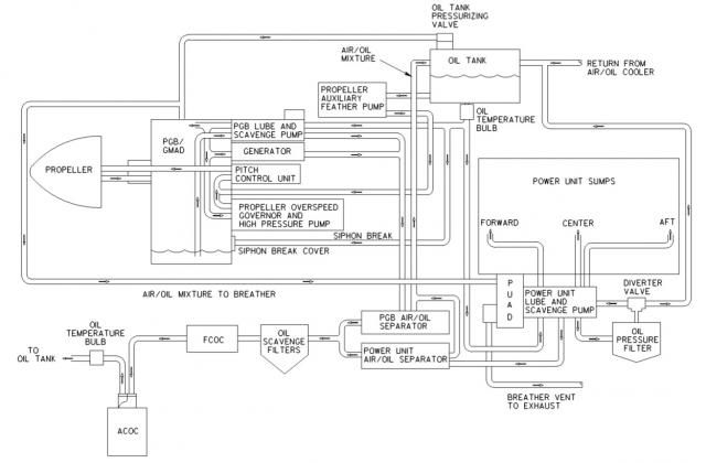
Although I'm not really full bottle on piston engines, hopefully this gas turbine engine oil system schematic can partially answer your question. In a gas turbine engine air is bled from the compressor to pressurise engine seals, so you can draw similarities between the two.

Image

As you can see, the oil is scavenged from the gearbox and power section sumps by two separate pumps where it proceeds through two separate air/oil separators. After passing through scavenge filters and coolers, it returns to the oil tank (bottom left of image up to top right of image. The air, however, is routed from the separators up to the oil tank. These lines can been seen up through the centre of the image.

At the top of the image is an oil tank pressurising valve. This valve maintains 8.5 PSIG in the tank, the rest is dumped via the pressurising valve. After being dumped, it is routed through the power section gearbox. At this point, the air still contains some oil. By routing it through the gearbox before it is vented overboard (in to the turbine exhaust, bottom right of image), oil loss is minimised.

riff_raff
riff_raff
132
Joined: 24 Dec 2004, 10:18

Re: Maximising Crankcase Negative Pressure

Post

braddock- An F1 engine lube oil system is much different than a turboprop aircraft engine/gearbox lube oil system. The F1 engine scavenge pumps extract a large volume of air with the oil. And this large volume of air entrained in the scavenged lube oil must be removed before the oil is fed back into the pressure pump. Race engines use both mechanical separators in the pump assy and dynamic separators (swirl pots) in the oil tank to remove air entrained in the scavenged oil flow. This task is quite difficult once you consider that the turnover rate of the lube oil volume is around 4-5 times per minute. As noted, it is critical to remove as much of the entrained air as possible from the lube oil delivered to the engine journal bearings to prevent damage to them.

With a turboprop aircraft, the engine and gearbox typically use different oil systems. As noted, the engine lube oil system must be capable of efficiently separating and expelling overboard the large volume of air leaked into the bearing chambers. But the oil flow volume in the engine is usually quite modest. The lube oil flow in the gearbox is much greater than that of the engine. But the gearbox lube system is sealed and there is not much air entrained in the scavenge oil flow.
"Q: How do you make a small fortune in racing?
A: Start with a large one!"

J.A.W.
J.A.W.
109
Joined: 01 Sep 2014, 05:10
Location: Altair IV.

Re: Maximising Crankcase Negative Pressure

Post

R-R, you do realize that the current F1s run a much reduced oil capacity,
- so likely run very restricted quantities of air/oil in the crankcases to be potentially whipped about as 'windage'..

Which really means.. ..'M.C.N.P.'
"Well, we knocked the bastard off!"

Ed Hilary on being 1st to top Mt Everest,
(& 1st to do a surface traverse across Antarctica,
in good Kiwi style - riding a Massey Ferguson farm
tractor - with a few extemporised mod's to hack the task).

riff_raff
riff_raff
132
Joined: 24 Dec 2004, 10:18

Re: Maximising Crankcase Negative Pressure

Post

JAW- Yes I do understand that modern F1 engines carry a very small volume of engine lube oil. And this makes the task of separating the air entrained in the lube oil that much more difficult. If we consider that the total volume of engine lube oil in the circuit of of an F1 car is say 5 liters, and the oil volume flow rate is 20 liters/min, that means the turnover rate of the oil volume is 4X/min, or once every 15 seconds.

Stop and think about how difficult it is to remove something like 95% of 20 liters worth of tiny air bubbles from 5 liters of lube oil within 15 seconds.
"Q: How do you make a small fortune in racing?
A: Start with a large one!"

J.A.W.
J.A.W.
109
Joined: 01 Sep 2014, 05:10
Location: Altair IV.

Re: Maximising Crankcase Negative Pressure

Post

riff_raff wrote:
Stop and think about how difficult it is to remove something like 95% of 20 liters worth of tiny air bubbles from 5 liters of lube oil within 15 seconds.

Hence all the more reason for evacuating the air.. ..by means of creating effective vacuum..

..less air = fewer "tiny air bubbles".. ( & aero-drag on recip' machinery)..
"Well, we knocked the bastard off!"

Ed Hilary on being 1st to top Mt Everest,
(& 1st to do a surface traverse across Antarctica,
in good Kiwi style - riding a Massey Ferguson farm
tractor - with a few extemporised mod's to hack the task).

riff_raff
riff_raff
132
Joined: 24 Dec 2004, 10:18

Re: Maximising Crankcase Negative Pressure

Post

The pumps scavenging the crankcase are positive displacement devices. This means they move a certain volume of air/oil during each rotation. The volume of oil/air that is taken in during each pump rotation remains constant until it is discharged into the pump outlet circuit. If there is any flow resistance in the pump outlet circuit, the fluid pressure of the oil/air mixture will increase, and the volume of the air entrained in the oil will decrease from being compressed.

One problem with low pressure air entrained in a liquid is that it can cause cavitation damage to the flow surfaces in the pump and engine if it causes the local vapor pressure of the hot fluid to drop below the point at which it will boil.
"Q: How do you make a small fortune in racing?
A: Start with a large one!"

J.A.W.
J.A.W.
109
Joined: 01 Sep 2014, 05:10
Location: Altair IV.

Re: Maximising Crankcase Negative Pressure

Post

So r-r, got any research based empirical-test numbers to back up that contention?
Such as boiling point/cavitation-erosion wear time/cycle factors - for current F1 scavenge systems/synthetic lubricants..
"Well, we knocked the bastard off!"

Ed Hilary on being 1st to top Mt Everest,
(& 1st to do a surface traverse across Antarctica,
in good Kiwi style - riding a Massey Ferguson farm
tractor - with a few extemporised mod's to hack the task).

riff_raff
riff_raff
132
Joined: 24 Dec 2004, 10:18

Re: Maximising Crankcase Negative Pressure

Post

J.A.W.-

Here's a quick read on gear pump cavitation problems caused by air entrained in lube oil.

Also, the damage produced on the flow surfaces of the pump is technically not "erosion". Instead it is surface spalling due to compressive fatigue failure. The combination of oil with a high temp flowing thru a section that produces low fluid pressure will result in entrained air bubbles rapidly expanding and collapsing, which creates extremely high pressures and stresses on the local surface.
"Q: How do you make a small fortune in racing?
A: Start with a large one!"

J.A.W.
J.A.W.
109
Joined: 01 Sep 2014, 05:10
Location: Altair IV.

Re: Maximising Crankcase Negative Pressure

Post

Technical semantics ( spalling/erosion = surface damage) aside r-r, do you have any references to cite?

Surely a lower air pressure value is going to reduce propensity for lubricating oil to be air saturated?

& esp' in a dedicated `2014 F1 low capacity/jet directed/high coolant factor/dry sump system..
..running very hi-tech anti-foam synthetic lubricant?
"Well, we knocked the bastard off!"

Ed Hilary on being 1st to top Mt Everest,
(& 1st to do a surface traverse across Antarctica,
in good Kiwi style - riding a Massey Ferguson farm
tractor - with a few extemporised mod's to hack the task).

J.A.W.
J.A.W.
109
Joined: 01 Sep 2014, 05:10
Location: Altair IV.

Re: Maximising Crankcase Negative Pressure

Post

Presumably sophisticated fluid-dynamics principles - as established long ago- by Coanda are being utilized..

http://www.flightglobal.com/pdfarchive/ ... 01600.html
"Well, we knocked the bastard off!"

Ed Hilary on being 1st to top Mt Everest,
(& 1st to do a surface traverse across Antarctica,
in good Kiwi style - riding a Massey Ferguson farm
tractor - with a few extemporised mod's to hack the task).

riff_raff
riff_raff
132
Joined: 24 Dec 2004, 10:18

Re: Maximising Crankcase Negative Pressure

Post

Sorry, I missed adding the link.

http://www.machinerylubrication.com/Rea ... cavitation

The issue of the mechanism behind cavitation surface damage to pump components is not "semantics". If you don't understand the fundamental process of how cavitation produces surface damage to pump components, then you will not appreciate the effect of air entrained in the oil flow.

As I tried to explain in a previous post, the scavenge pumps used on F1 engines are positive displacement devices. This means they move a fixed volume during each cycle. This displaced volume is independent of pressure. So even if the ambient crankcase air pressure is low, the same volume of air will still be pumped, but It will just be a lower mass of air.

Cavitation damage results from the ambient pressure in a fluid flow falling below the fluid vapor pressure. This causes the fluid to boil, which means any gas entrained in the fluid will come out of suspension, forming bubbles on the flow surfaces that rapidly expand and burst, which produces very high compressive stresses on the flow surfaces. This is the reason engine coolant circuits are pressurized- to prevent cavitation problems.
"Q: How do you make a small fortune in racing?
A: Start with a large one!"

J.A.W.
J.A.W.
109
Joined: 01 Sep 2014, 05:10
Location: Altair IV.

Re: Maximising Crankcase Negative Pressure

Post

riff_raff wrote:Sorry, I missed adding the link.

http://www.machinerylubrication.com/Rea ... cavitation

The issue of the mechanism behind cavitation surface damage to pump components is not "semantics". If you don't understand the fundamental process of how cavitation produces surface damage to pump components, then you will not appreciate the effect of air entrained in the oil flow...
This is the reason engine coolant circuits are pressurized- to prevent cavitation problems.
Well, r-r, your link does not mention F1 scavenge conditions, nor relative vacuum/ambient air pressure values/effects..
..it does relate cavitation as a form of working surface "erosion" however..

Perhaps r-r, you could cite relevant data - which will show your ability to "appreciate" - the O.P.?
"Well, we knocked the bastard off!"

Ed Hilary on being 1st to top Mt Everest,
(& 1st to do a surface traverse across Antarctica,
in good Kiwi style - riding a Massey Ferguson farm
tractor - with a few extemporised mod's to hack the task).

Tommy Cookers
Tommy Cookers
638
Joined: 17 Feb 2012, 16:55

Re: Maximising Crankcase Negative Pressure

Post

riff_raff wrote: Cavitation damage results from the ambient pressure in a fluid flow falling below the fluid vapor pressure. This causes the fluid to boil, which means any gas entrained in the fluid will come out of suspension, forming bubbles on the flow surfaces that rapidly expand and burst, which produces very high compressive stresses on the flow surfaces. This is the reason engine coolant circuits are pressurized- to prevent cavitation problems.
conventionally, cavitation in a cooling circuit is known for the vapourisation producing local overheating ?

we Brits had in the early 60s the fine Daimler 4.5 litre hemi V8 with fine aluminium alloy heads
within the warranty period it ate holes in its heads due to cavitation
unlike the 2.5 litre Daimler V8, the 4.5 litre was not made in quantity (it could have been in Can-Am etc rather than the Olds ?)