Khamsin Virtual Racecar Challenge 2015

Post here information about your own engineering projects, including but not limited to building your own car or designing a virtual car through CAD.
User avatar
variante
131
Joined: 09 Apr 2012, 11:36
Location: Monza

Re: Khamsin Virtual Racecar Challenge 2015

Post

Same concept, simplified:
Image
Image

About making LMP1 look alike models, it's not a problem for me. However it would be interesting to see what happens with more open regulations (i imagine LMP cars with actual front wings, coke bottles rear ends,...)

User avatar
CAEdevice
45
Joined: 09 Jan 2014, 15:33
Location: Erba, Italy
Contact:

Re: Khamsin Virtual Racecar Challenge 2015

Post

Over the weekend I read the rulebook in detail. Compared to last year it seems clearer and more concise, great job!

I welcome any proposal in favor of realism (K3.5, K3.6), but I would agree the proposal to make the LMP1 based rules less stringent, for example working on the dimensions of the regulated areas.

One question about the CAD template: does the suspension geometry represent the volume occupied during the movement? In the final version would be useful to have also the nominal geometry of the suspension in order to correctly simulate the flow.

Thanks for geometry in STEP format.

Now some questions that not related to the technical rules:

1) The solver will still be based on OpenFOAM? Any news on the decision to make it public?

2) I am glad see the participation of Variante and MadMatt, but I hope the see more people here. Is there a kind of promotion program, in order to increase the number of participants? If there was something like a "press kit" I could try to promote the challange (on my website for example). It would be a good idea to try to involve schools too.

julien.decharentenay
10
Joined: 02 Jun 2012, 12:31

Re: Khamsin Virtual Racecar Challenge 2015

Post

Thanks Chris for looking after the rule book.

From my side, things have been very busy with a change of job and country. I will be UK based from next week and will ramp up my KVRC activities.

The CFD modelling will be openFoam based as license costs would make such challenge unpractical without the collaboration of a CFD software vendor. I am looking to pull a few strings to get more free computational resources, which would allow for increased mesh resolution...

My to-do list includes linking with Universities to engage with first and second year engineering students to raise awareness of KVRC to try to get more participants. Currently this is very much in concept stage and much has to be done...

User avatar
CAEdevice
45
Joined: 09 Jan 2014, 15:33
Location: Erba, Italy
Contact:

Re: Khamsin Virtual Racecar Challenge 2015

Post

I think that a openFoam based solver is the best choice because OpenFoam can be considered the "universal" solver at the state of art.

User avatar
CAEdevice
45
Joined: 09 Jan 2014, 15:33
Location: Erba, Italy
Contact:

Re: Khamsin Virtual Racecar Challenge 2015

Post

Hi, what about the proposal K3.5, K3.6, K3.7?

I think that if all the proposal will be applied some ideas could not be realised, but if none of them will be confirmed, cars will look like airplanes...
I would agree to mantain at least K3.7.

cdsavage
19
Joined: 25 Apr 2010, 13:28

Re: Khamsin Virtual Racecar Challenge 2015

Post

Apologies for the lack of updates. Changes have been made to the guide parts (visibility template and RW template) and rulebook (wording) based on the feedback so far. I will wait until the next revision before posting new links, since the changes were minor.
CAEdevice wrote:I welcome any proposal in favor of realism (K3.5, K3.6), but I would agree the proposal to make the LMP1 based rules less stringent, for example working on the dimensions of the regulated areas.
Do you mean to change the boxes we have now, or to add further rules from the LMP1 rulebook, but modify those rules to allow larger zones for bodywork?

Something to keep in mind with trying to use rules straight from the LMP1 rulebook - the P1 rulebook is slightly different to the F1 rulebook in that the regulations aren't defined quite as much by a set of boxes, but often by wording which completely bans aerodynamic devices outside of some exceptions. For KVRC, the F1 method of regulation works pretty well but the LMP1 style less so.
CAEdevice wrote:One question about the CAD template: does the suspension geometry represent the volume occupied during the movement? In the final version would be useful to have also the nominal geometry of the suspension in order to correctly simulate the flow.
Yep, the parts are meant to represent the entire volumes occupied by the suspension members as they move. I will include the actual suspension parts separately in the next release, keeping in mind that these parts have no bearing at all on regulations, they are only there for CFD purposes.
CAEdevice wrote:Hi, what about the proposal K3.5, K3.6, K3.7?

I think that if all the proposal will be applied some ideas could not be realised, but if none of them will be confirmed, cars will look like airplanes...
I would agree to mantain at least K3.7.
I am leaning towards leaving 3.7 out, since the front suspension already has to be covered from the front and top. With the added constraint of K3.7 it just makes a building a car with a front wing more difficult in terms of meeting the regulations.

Not sure yet about 3.5 and 3.6.

I am open to input on the dimensions of the diffuser. Perhaps a slightly lower maximum height while keeping the start position in Y the same as it is now.
eyalynf1 wrote:My difficulty has been having time to complete the modeling alone. So from a purely selfish stand point, I'd like to see the modeling effort required reduced so that I can get to the CFD part more quickly.

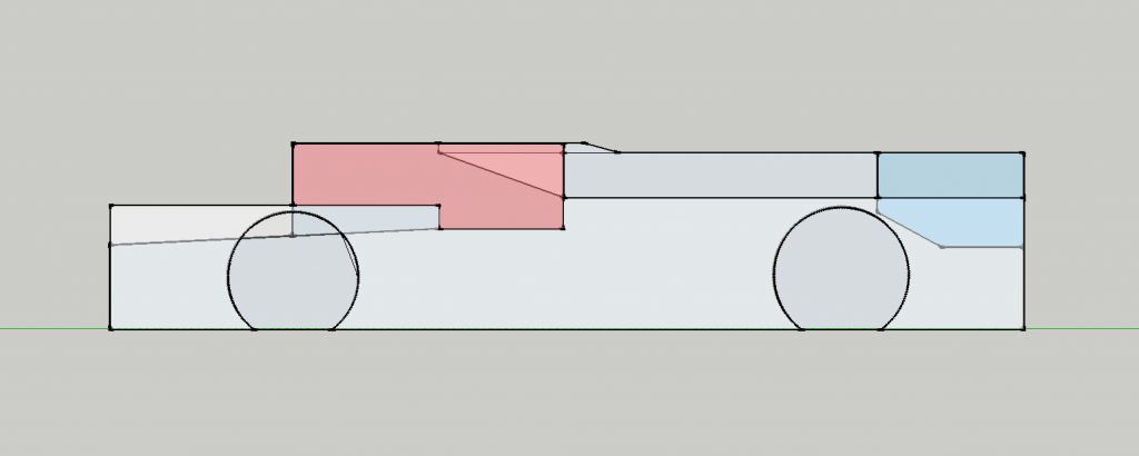
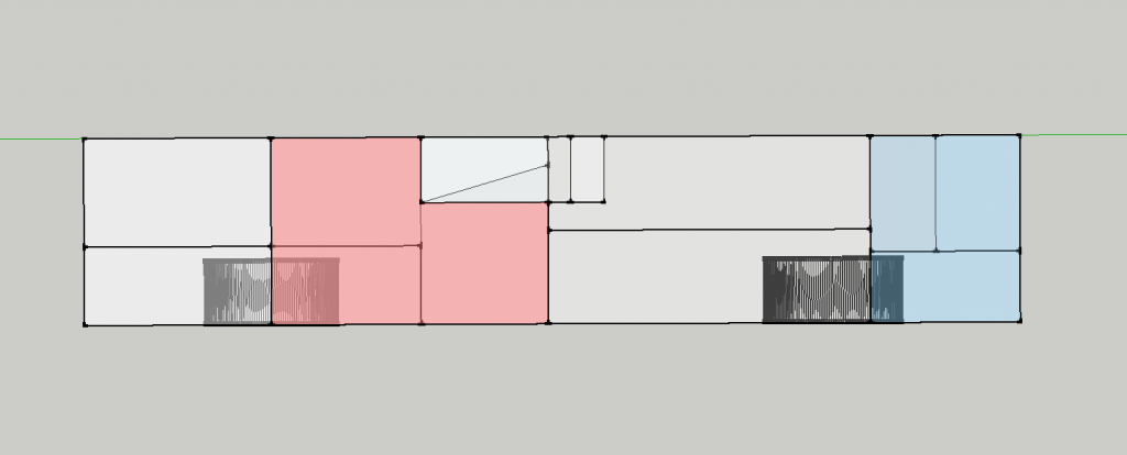
For me, this would mean more spec parts, with customization limited to 1 or 2 handfuls of areas. Say a box between the wheels on the sides, a box in front of the front wheels, behind the back wheels, and above the back box. A bit limiting, yes, but if the point is to disseminate and develop CFD software, skills, and use, then getting competitors to the CFD but faster would seem logical.
I just wanted to highlight this post from earlier on - while I can't guarantee we will have time to do this, we would like to supply some optional basic parts to make things easier. Most likely a central set of bodywork forming the nose /tub / engine cover, and fenders to cover the front and rear wheels, as a minimum.

MadMatt
125
Joined: 08 Jan 2011, 16:04
Contact:

Re: Khamsin Virtual Racecar Challenge 2015

Post

I am a bit confused at rule K2.5:

"From any other viewing angle ahead of the rear wheel centerline which is above and to the side of the car, no part of the rear suspension volumes may be visible."

Does that mean the rear suspension parts cannot be seen from a person standing in front of the rear axle line no matter where?

Also another question about K3.1. What happens in the area from 0 to 300mm behind the forward most surface of the control volume? The crash structure has to expend but I read:

"At a plane located between 0 and 300mm rearwards of the forwardmost face of the bodywork volume, the intersection with the front crash structure forms one or more closed shapes. Excluding any areas more than 300mm from the car centerline, the shape(s) must be at least 16000mm^2 in total area."

However it is impossible to have a surface of 16000mm^s at a plane 1mm ahead of that forward most surface since the crash structure is just starting. Is it not only at 300mm that there must be a minimum of 16000mm^s of surface for that crash structure?

User avatar
CAEdevice
45
Joined: 09 Jan 2014, 15:33
Location: Erba, Italy
Contact:

Re: Khamsin Virtual Racecar Challenge 2015

Post

Hi MadMatt, I think that your interpretation of k2.5 is correct.

About point k3.1, this is my interpretation: there must be a 16000mm2 section at a plane located between 0mm and 300mm from the most forward point and the section area must be equal or greater than 16000mm2 forward that plane (measured as described).

Hi cdsavage, thanks for your answers.

About the "box dimensions": i would reduce the lenght of the frontal extension of the cooling inlets (1000mm >>> 900/800mm) and I would add this rule: "no bodywork could be placed into the volume generated by a blend between the cooling inlet and outlet surface. Sorry if there is something like this that I have not noticed yet.

About the diffuser: I would not modify the box dimensions, the length/heigth ratio is realistic.

K3.7: I agree with you, my previous interpretation of the rule was wrong.

K3.5 and K3.6: A way to keep the car realistic without reducing the design freedom could be to not apply K3.5 and k3.6 rules, but at the same time to increase the total cooling inlets surface (150000 or 180000 mm2 instead of 100000 mm2) with a shorter frontal extension (not 1000mm but 700/800mm) and a bigger distance between inlet and outlet (now 600mm).

Last point: at the moment it seems to me that "double" or "overlapped" diffuser are allowed, I'm I right?
Last edited by CAEdevice on 25 Nov 2014, 23:17, edited 1 time in total.

MadMatt
125
Joined: 08 Jan 2011, 16:04
Contact:

Re: Khamsin Virtual Racecar Challenge 2015

Post

K1.4: So any part cannot be less than 20mm at any point? Is it possible to start with a square shape of 20mm thickness and then radius it to get a trailing edge? 20mm is quite big in my opinion. Would it be possible to at least sharpen the leading edge as well so get don't get these horrible flat surfaces presented to the wind? :)

I take as an example a rear view mirror mount. 20mm thick is not pretty when it should be 3mm! :)

astracrazy
31
Joined: 04 Mar 2009, 16:04

Re: Khamsin Virtual Racecar Challenge 2015

Post

Hi Guys

Just dropping in to say I will no longer be part of the KVRC project. As most of you, those who have been involved regularly, might of noticed I haven't been around so much. The plan was I would always being stepping back for the 2015 due to having less time myself, but to be truthful I have barely been involved at all so far.

I'll still keep popping in and having a look how things are going and may even be able to get involved again next year.

But for now, thanks everyone who took part while I was involved. I like to think we really moved KVRC in a good direction during the 2014 project and Chris, Nick and Julien look like they are taking it to another level.

User avatar
CAEdevice
45
Joined: 09 Jan 2014, 15:33
Location: Erba, Italy
Contact:

Re: Khamsin Virtual Racecar Challenge 2015

Post

Hi astracracy, best wishes for your projects and thanks for your perfect job during 2014.

MadMatt
125
Joined: 08 Jan 2011, 16:04
Contact:

Re: Khamsin Virtual Racecar Challenge 2015

Post

Following my question 2 messages above regarding the 20mm thickness, I would like to ask questions about the CFD methodology. How is it gonna be simulated?

- Moving wheels?
- Moving floor?
- Sea level conditions (air density, viscosity)?
- Air velocity?

As I am having a break from my laptime simulator project, I gave it a go at this one, and came up with a preliminary design. Eventho I won't put it straight into my CFD software to get a benchmark, it would be good to know what kind of car we are aiming to get.

Also will the rediator templates be provided?

Thanks! :)

cdsavage
19
Joined: 25 Apr 2010, 13:28

Re: Khamsin Virtual Racecar Challenge 2015

Post

Thanks to Luke for his contribution so far.
MadMatt wrote:I am a bit confused at rule K2.5:

"From any other viewing angle ahead of the rear wheel centerline which is above and to the side of the car, no part of the rear suspension volumes may be visible."

Does that mean the rear suspension parts cannot be seen from a person standing in front of the rear axle line no matter where?
Yes, this rule is a bit vague but you have the right idea. This might change if we can find a better way to describe this.
MadMatt wrote:Also another question about K3.1. What happens in the area from 0 to 300mm behind the forward most surface of the control volume? The crash structure has to expend but I read:

"At a plane located between 0 and 300mm rearwards of the forwardmost face of the bodywork volume, the intersection with the front crash structure forms one or more closed shapes. Excluding any areas more than 300mm from the car centerline, the shape(s) must be at least 16000mm^2 in total area."

However it is impossible to have a surface of 16000mm^s at a plane 1mm ahead of that forward most surface since the crash structure is just starting. Is it not only at 300mm that there must be a minimum of 16000mm^s of surface for that crash structure?
There is a single plane anywhere between 0 and 300mm rearward of the front face (this has been changed to read between 700mm and 1000mm forward of the front wheel CL). You decide exactly where this plane is, and then the area of the intersection(s) at that plane are measured. We can probably change it to just "at 300mm rearward" rather than "between 0 and 300mm rearward".
CAEdevice wrote:About the "box dimensions": i would reduce the lenght of the frontal extension of the cooling inlets (1000mm >>> 900/800mm) and I would add this rule: "no bodywork could be placed into the volume generated by a blend between the cooling inlet and outlet surface. Sorry if there is something like this that I have not noticed yet.
There is a vague rule about there being a plausible path for air to flow from the inlet to the outlet (but this internal path doesn't need to be modeled). It's at the end of K4.2.
CAEdevice wrote:Last point: at the moment it seems to me that "double" or "overlapped" diffuser are allowed, I'm I right?
Correct, at the moment this is allowed. I think it's very likely we will add a rule stating "when intersected with a plane normal to the X-axis, must form a single, uninterrupted line entirely visible from below" applying to bodywork in the diffuser area, unless anyone has a good reason we should leave it like it is.
MadMatt wrote:K1.4: So any part cannot be less than 20mm at any point? Is it possible to start with a square shape of 20mm thickness and then radius it to get a trailing edge? 20mm is quite big in my opinion. Would it be possible to at least sharpen the leading edge as well so get don't get these horrible flat surfaces presented to the wind? :)

I take as an example a rear view mirror mount. 20mm thick is not pretty when it should be 3mm! :)
I'll reduce this to 10mm, but anything less than that would probably be too small. Keep in mind that very thin parts can cause problems at the meshing stage. A semi-circular leading edge is fine, I'll add an image to the rulebook to guide this.
MadMatt wrote:Following my question 2 messages above regarding the 20mm thickness, I would like to ask questions about the CFD methodology. How is it gonna be simulated?

- Moving wheels?
- Moving floor?
- Sea level conditions (air density, viscosity)?
- Air velocity?

As I am having a break from my laptime simulator project, I gave it a go at this one, and came up with a preliminary design. Eventho I won't put it straight into my CFD software to get a benchmark, it would be good to know what kind of car we are aiming to get.

Also will the rediator templates be provided?
This isn't set in stone yet, but we will be building on what we used in 2013 and 2014, with some additions, such as simulated inlet and outlet surfaces. There will be moving wheels and a moving ground plane.

Radiator templates will be provided, but the inlet will be a simple rectangular shape, so you will probably end up wanting to use your own anyway.

MadMatt
125
Joined: 08 Jan 2011, 16:04
Contact:

Re: Khamsin Virtual Racecar Challenge 2015

Post

Thank you! Much clearer now :) I guess there will be 3 kinds of designs (to to mention mixes of 2 or the 3):

- Group C type
- LMP type
- F1 type

I think it will be very interesting to see who choose what and how far people go with their design. I agree that the design is quite restrictive, but at least it removes possibilities that would cause too big differences in the results, so its good!

User avatar
CAEdevice
45
Joined: 09 Jan 2014, 15:33
Location: Erba, Italy
Contact:

Re: Khamsin Virtual Racecar Challenge 2015

Post

MadMatt wrote:Thank you! Much clearer now :) I guess there will be 3 kinds of designs (to to mention mixes of 2 or the 3):

- Group C type
- LMP type
- F1 type

I think it will be very interesting to see who choose what and how far people go with their design. I agree that the design is quite restrictive, but at least it removes possibilities that would cause too big differences in the results, so its good!
Hi Matt, I think that with a C Group style it would be difficult to have a good balance (too much DF on the rear axle, because the diffuser area is concentrated on the rear axle).

At the moment I have not a real 2015 design, I just modified my F1 2014 with larger rear wing and diffuser and covered suspensions. I have the impression that covered wheels are and advantage, but covered suspensions are quite difficult to manage.

It would be very important the final decision about K3.5, K3.6,

I was also wondering wich will be max power available.

Post Reply