As promised, an analysis concerning the aerodynamics of the Variante Livore
Designed to achieve the greatest amount of downforce, it managed to win the first race of the KVRChampionship which took place (virtually...) on the Nurburgring Nordschleife.
This iconic track demands a very high level of downforce as the car has to handle more than 70 tortuous corners at very high average speeds. The presence of long straight lines, however, imposes the production of downforce to be decently efficient, as opposed to tracks such as Monaco.
The Livore was, indeed, originally designed to produce large amounts of downforce in the most efficient way in order not to repeat last season's experience, where a generally good car -the Variante Ira- was limited by its high drag characteristics.
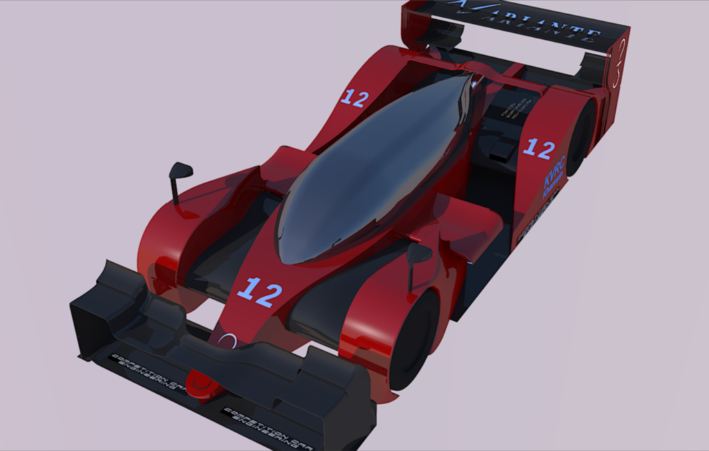
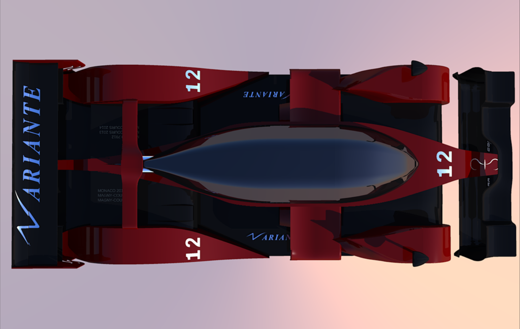
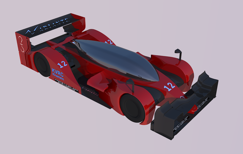
To achieve that target, the classical LMP bodywork design was abandoned in favour of a more radical approach, characterized by a water drop-shaped front end followed by a tight rear bodywork: a solution that allows for a greater airflow to the rear end of the car. The water drop shape itself has got intrinsic low drag characteristics and is very stable when subject to aiflows coming from different directions (
meaning, for example, that this part of the bodywork will be easily adaptable when the Front Wing AoA will be changed for the following races).
About the
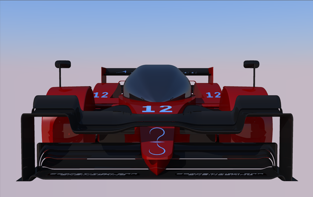
FRONT END
Despite being designed, originally, similarly to an LMPrototype front end, the increasing level of downforce required to balance the rear diffuser and wing imposed a heavy revision of this area, now characterized by a massive double tier wing.
This layout was chosen over the classical diffuser shape in order to minimize the connections and interactions with the following bodywork, thus minimizing downforce dissipation (which can be observed anyway, in a smaller amount, on the top of the front suspensions cover...).
About the
MAIN BODY
Integration of the parts and overall elegance were keywords for this car. This chain of interactions explains what it really means:
The
front suspensions/wheels cover, receiving air from the front wing in the least intrusive and most gentle way, directs the airflow around the
sidepods and to the
side impact structures cover with the optimal orientation; the latter are shaped so that they generate a moderate amount of downforce not to disrupt the airflow to the rear wing, which gets cleaned up and redirected by a
winglet over the rear wheel arches, which also houses takes advantage of the
exhaust pipes that, in turn, accelerate air to the
rear wing.
About the
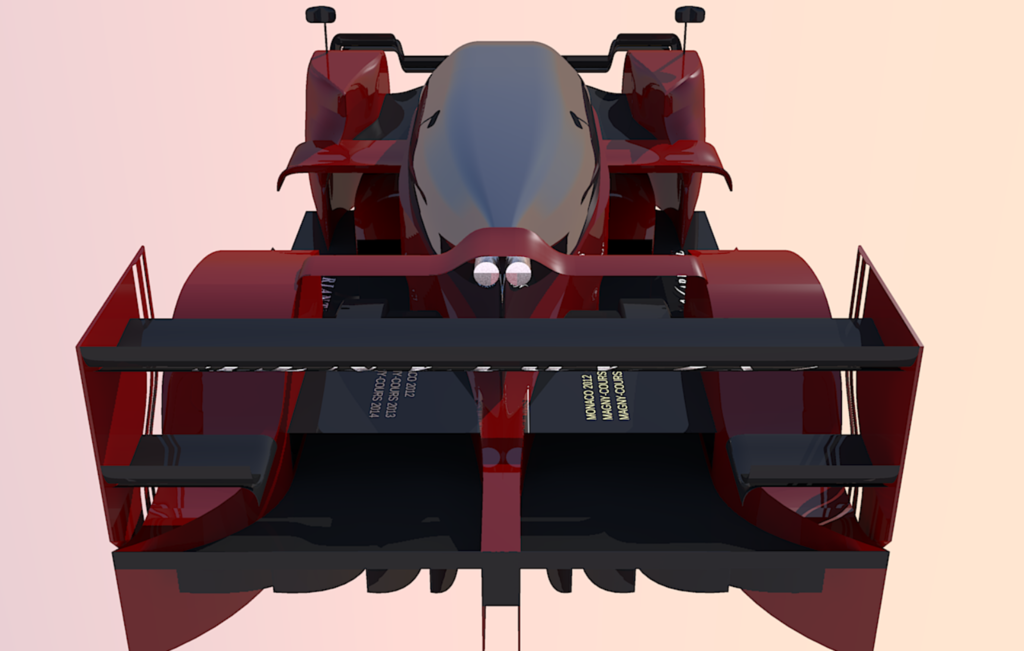
REAR END
Quite obviously, the two protagonists of this area are: diffuser and rear wing. While for the wing the only development work concerned airfoils, the diffuser required a far greater effort. That is an element capable of generating more than 50% of the total downforce, so it's definetely worth putting some effort in it...
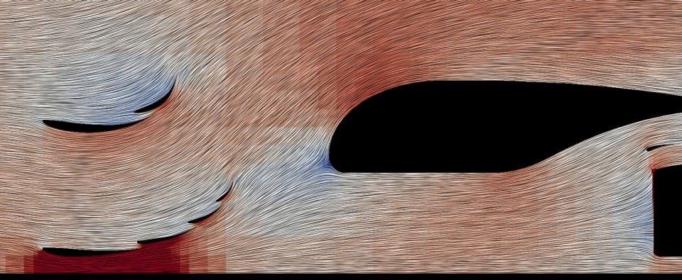
The diffuser funcions tridimensionally, therefore both its profile and its plan view shape had to be developed in parallel. As for the profile, maximizing airflow extraction and acceleration from the undebody was the main aim, which has been fullfilled using a hybrid diffuser (concave/convex). On the other hand, the plan view shape had to be designed considering the inward suction, caused by the low pressure under the car, and the strong inwash, caused by the tyres.
While inward suction and inwash may be seen as negative aspects that increase pressure under the body of the car and disrupt a linear airflow, they can be used in a constructive way: in fact, the so formed transversal flows can interact with the walls of the diffuser, shedding one strong vortex each side of the car, thus increasing downforce and flow predictability along diffuser's lenght.
Finally, well studied strakes have been a determinant factor in further downforce production, as they have the property to stabilize the flow, ridistributing pressure zones in strategic points, as well as energize it shedding smaller vortices.
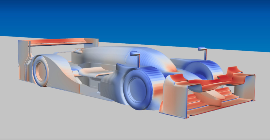
I cannot show pictures of the diffuser, for obvious reasons, but here are the forces distribution:
Drag
Downforce
Hope this helps a bit those who are new to aerodynamics.
If you've got questions or want me to describe a topic depth, just ask