Beautiful article, Mantium. Thank you for sharing.
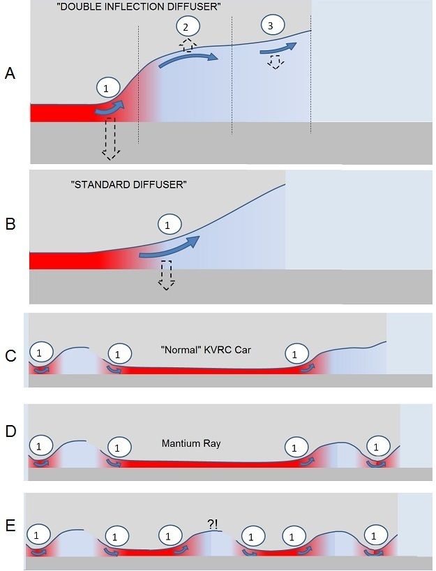
About your diffuser: I think the reason why it works could be found in the compression/decompression process and its ground effect interactions. As the incoming air approaches the diffuser's "protuberance" it slows down in its compression stage, far away from the ground; energy "recovery" is fullfilled during the decompression stage, near to the ground. It should be also noticed that the pressure differential generally reaches higher values during the decompression phase. As a third observation, in a well designed geometry potential energy of the compression phase can be stored mostly in form of drag (instead of lift) and released in form of downforce.
I think that your current design lacks a little bit of the optimization to fully take advantage of this last point. Still it looks very promising.
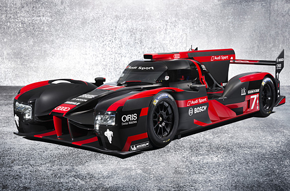
A similar device is the "pelican nose" pioneered by Lotus. I believe it works in the very same way.
- Login or Register
No account yet? Sign up