In this thread I will be unlocking a few secrets hidden within this part - The Pneumatic Valve Spring, mainly its construction, the parts inside and how they go together. To my knowledge, this is the first time a complete Pneumatic Valve Spring has ever been seen in the public domain in its entirety - exposing all components in great detail. While I have in the past shown parts of an older style assembly - this Pneumatic Valve Spring is from one of the last V8 engines, and one that had a 20,000rpm+ rev limit. I am aware that a similar Pneumatic Valve Spring has featured in the past in a Magazine, but the article was disappointing to say the least in terms of displaying and describing possibly one of the most interesting and critical parts within any F1 engine we have seen so far. Given the new lower engine rpm operating range which is now in place, we may never again see or have use for such an assembly of which huge performance demands were placed upon it.
These Pneumatic Valve Springs are now available to purchase at considerable cost, but actually finding a vendor that will take you serious definitely out-weighted the cost on this one.
I am not going to mention the engine makers name all the same just In-case Ive missed some small print.
In terms of Engineering Design, getting my hands on this Pneumatic Valve Spring meant a lot to me. I'm years trying to obtain one - I got so close so many times and the deal would either fall through, or the assembly would be incomplete on close inspection. I owe a huge thanks to many people along the way that took pictures of what they had or patiently replied to countless emails, from memorabilia specialists, to F1 Mechanics, Random ebayers, all the way to F1 Engine Manufacturers. I owe a huge and special thanks to the Company that was able to supply in the end - having this item now closes an unfinished chapter for me that was always in the back of my mind. I believe the Design Engineers that managed to create this assembly and get it to be reliable deserve recognition for years to come - as mentioned, it may never be done again.
Enough of the back story and onto the part.
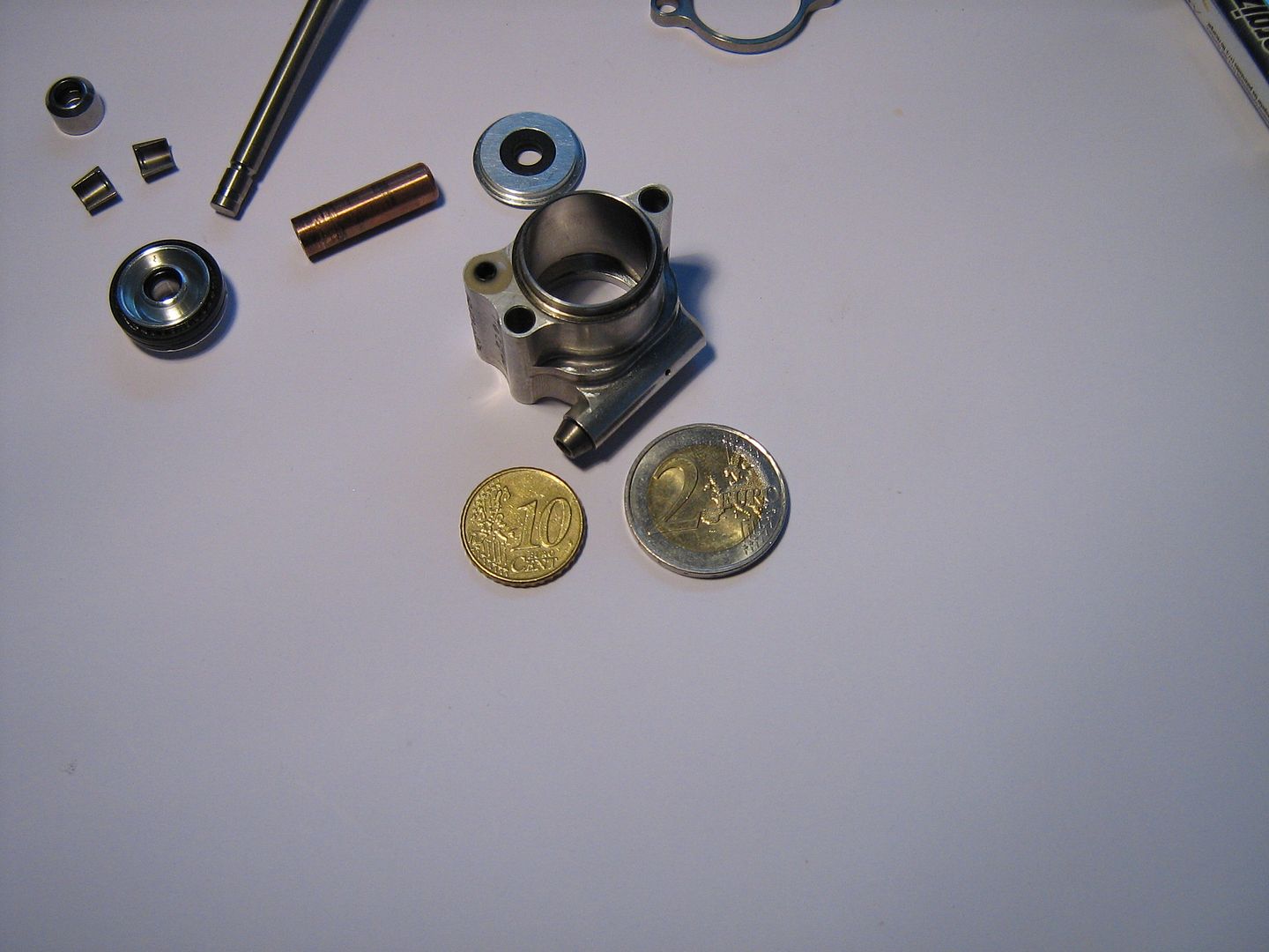
First off, the smallness of the Pneumatic Valve Spring surprised me, as did the method used to manufacture the bore/barrel assembly. Since I had obtained a much older assembly years ago I have something to compare the much later and higher revving design to - the 10yr(approx) gap between both designs is now very apparent.
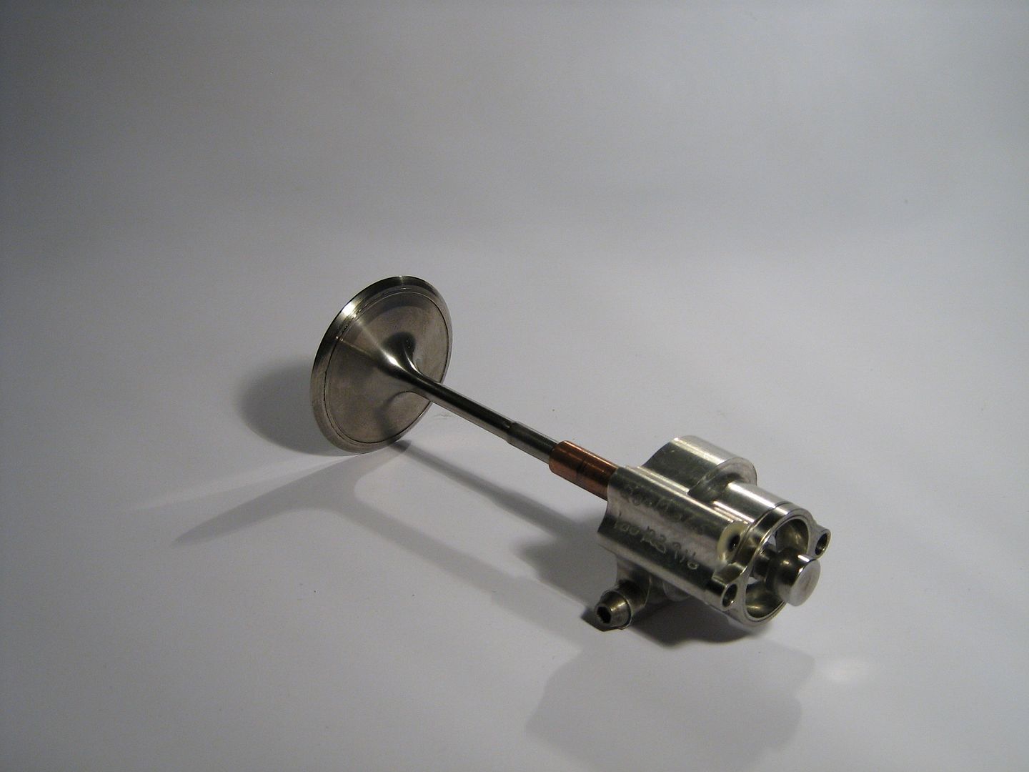
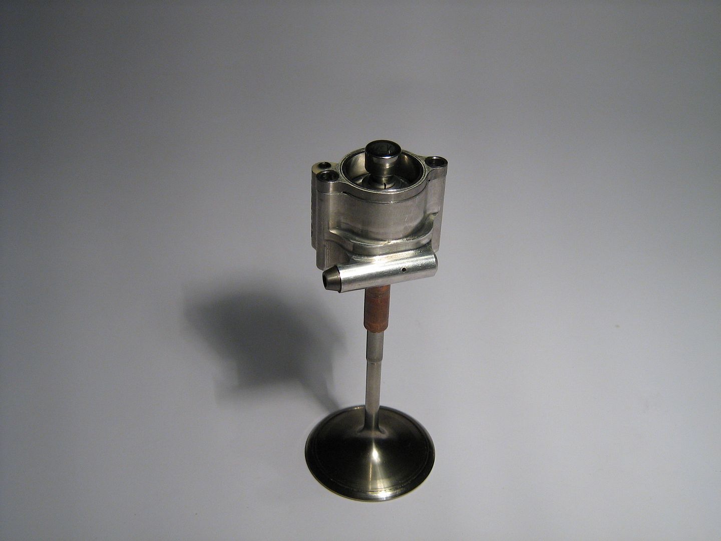
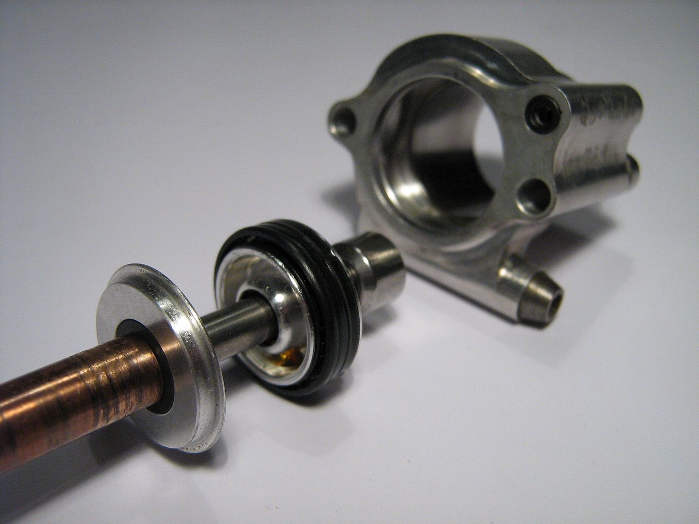
Below is the full Pneumatic Valve Spring assembly pictured in its complete state. I've decided the best way to display all is to break down the assembly in stages and try describe each part as I progress.
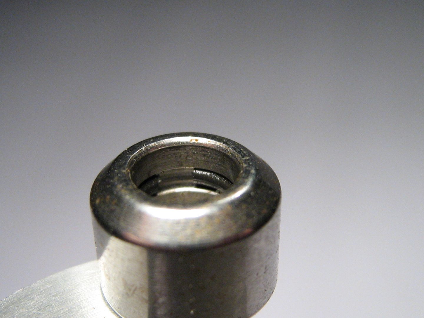
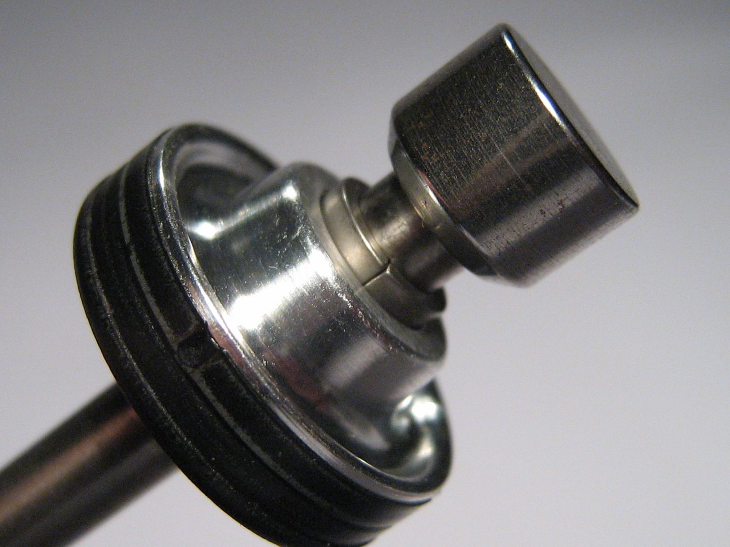
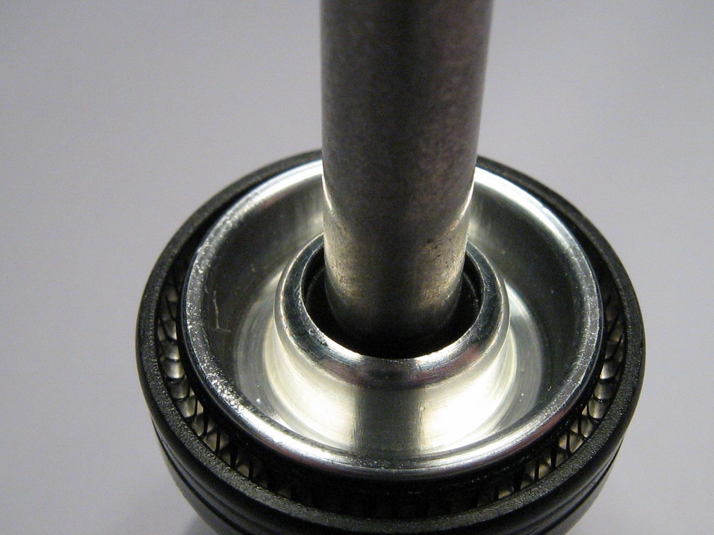
A shot down the top of the lash cap still affixed to valve stem on which the finger follower presses,
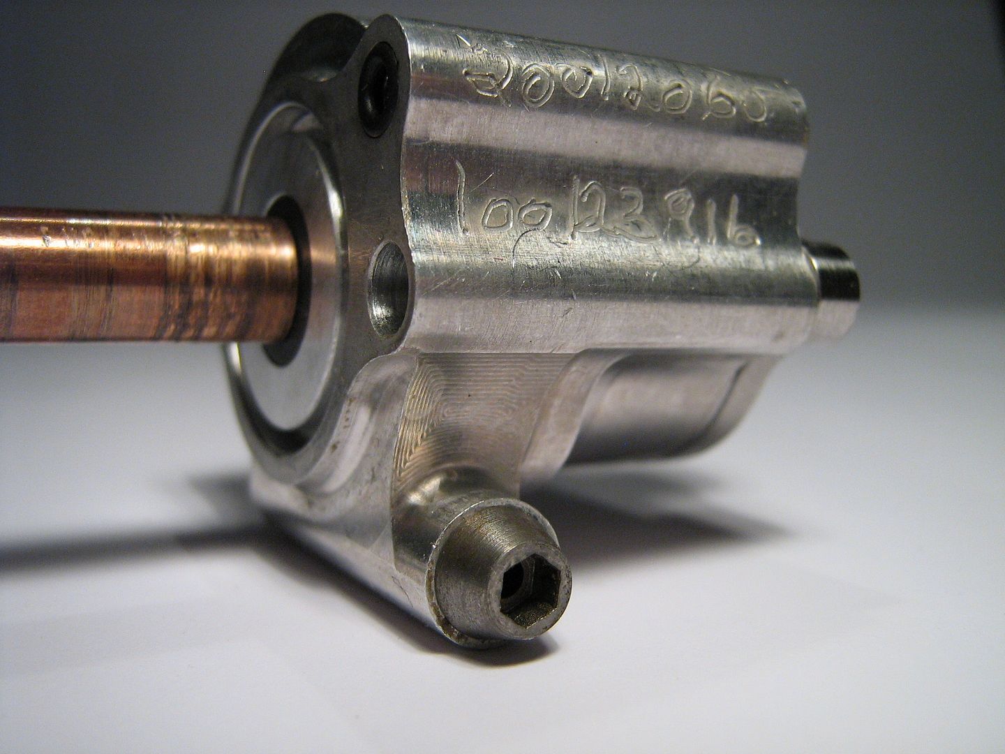
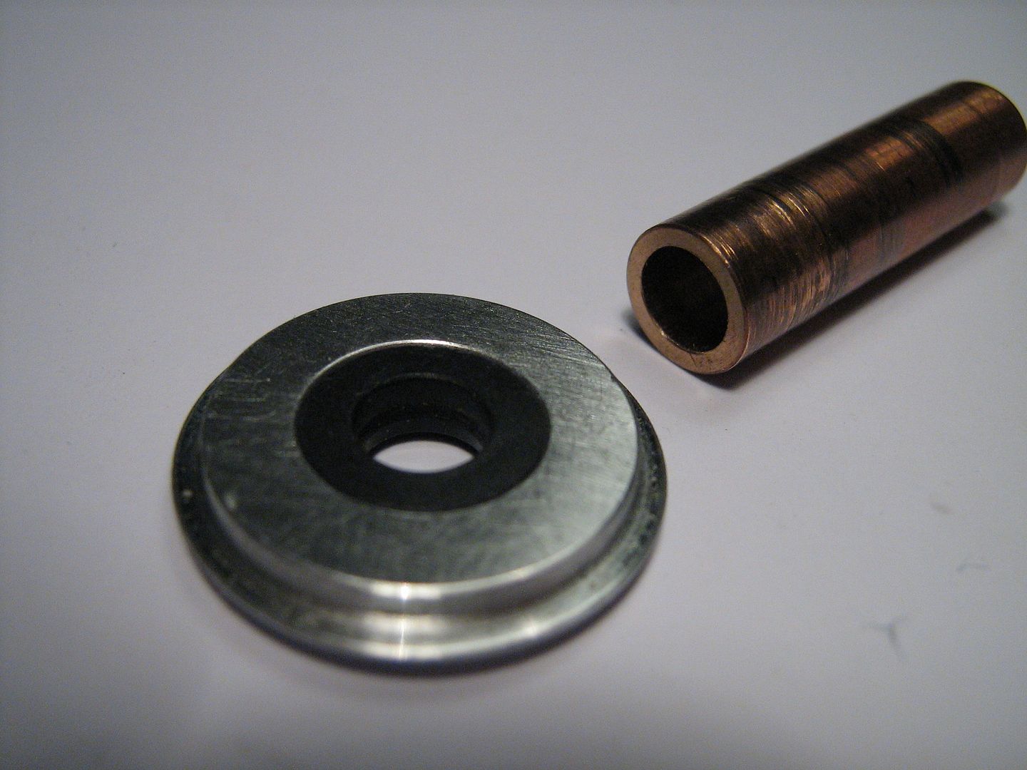
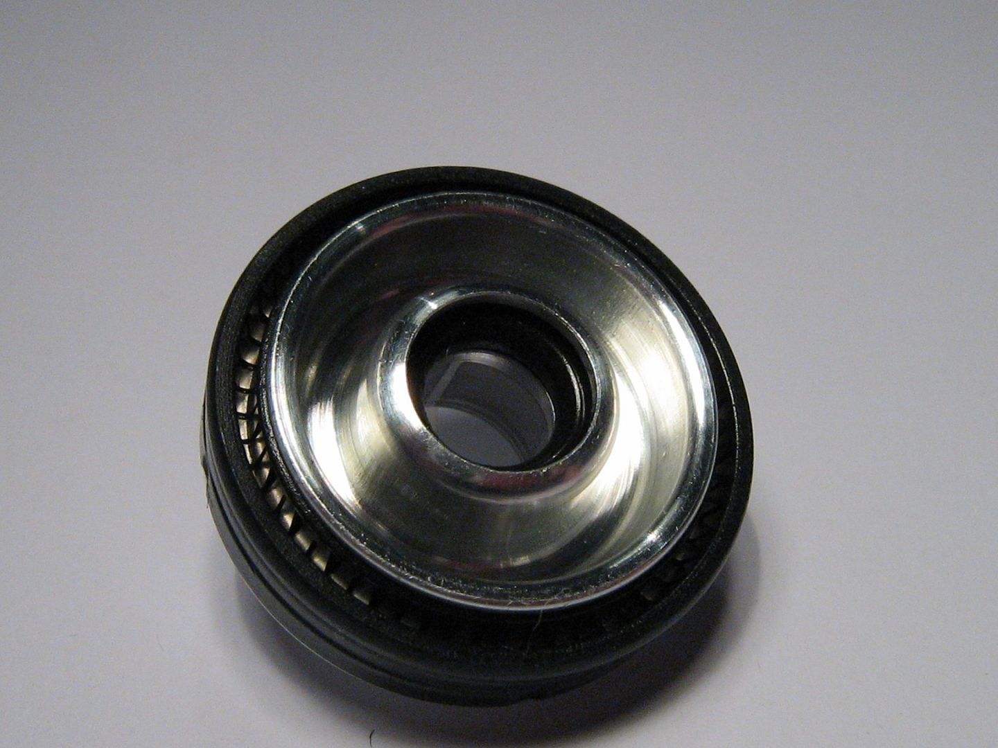
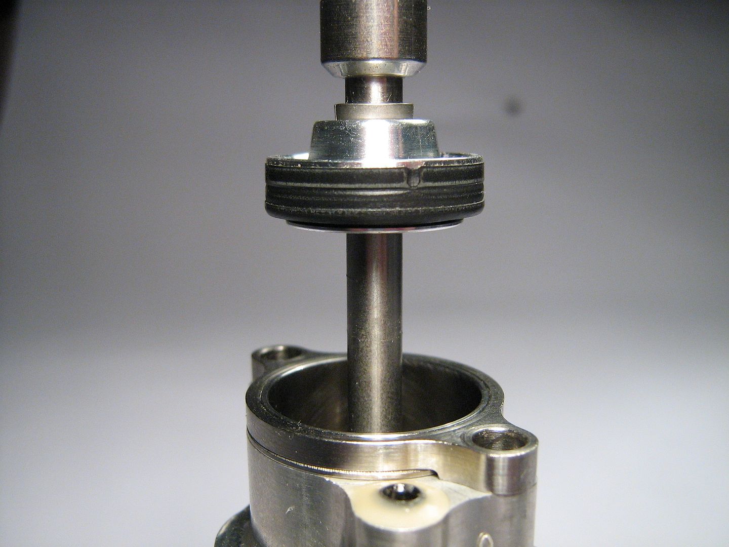
A shot of the valve exiting lower sealing disk as well as the separate valve guide, valve stem diameter is just 5mm. Since this is the base of the assembly it is this side that sits onto head - for clarity I have removed the sealing o-ring from the groove which can be seen below. This o-ring seals the disc containing lower valve seal to both the main assembly body, and also the cylinder head mounting area,
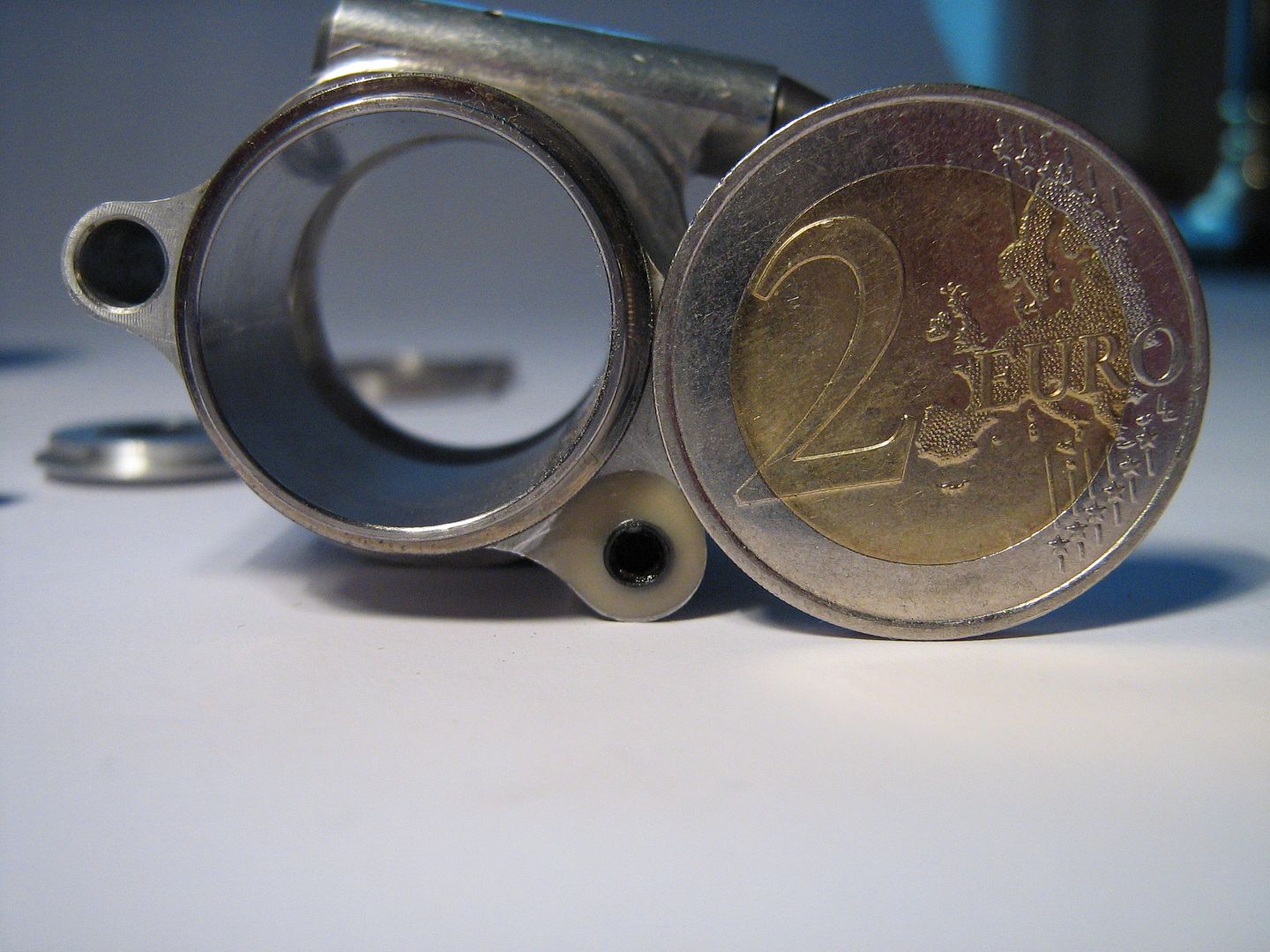
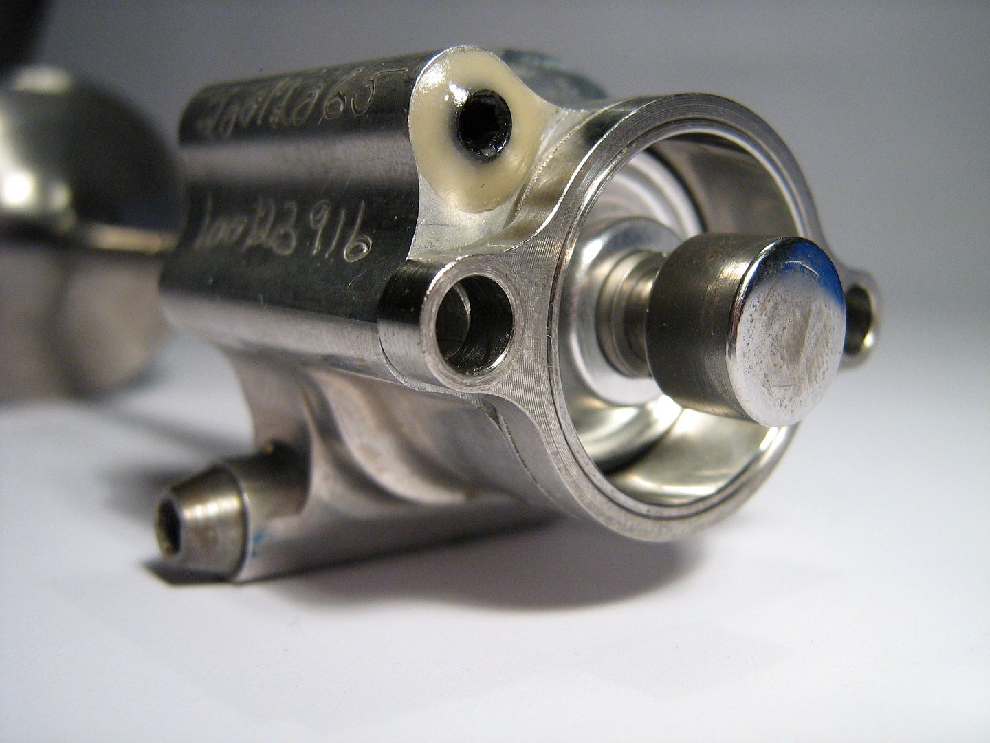
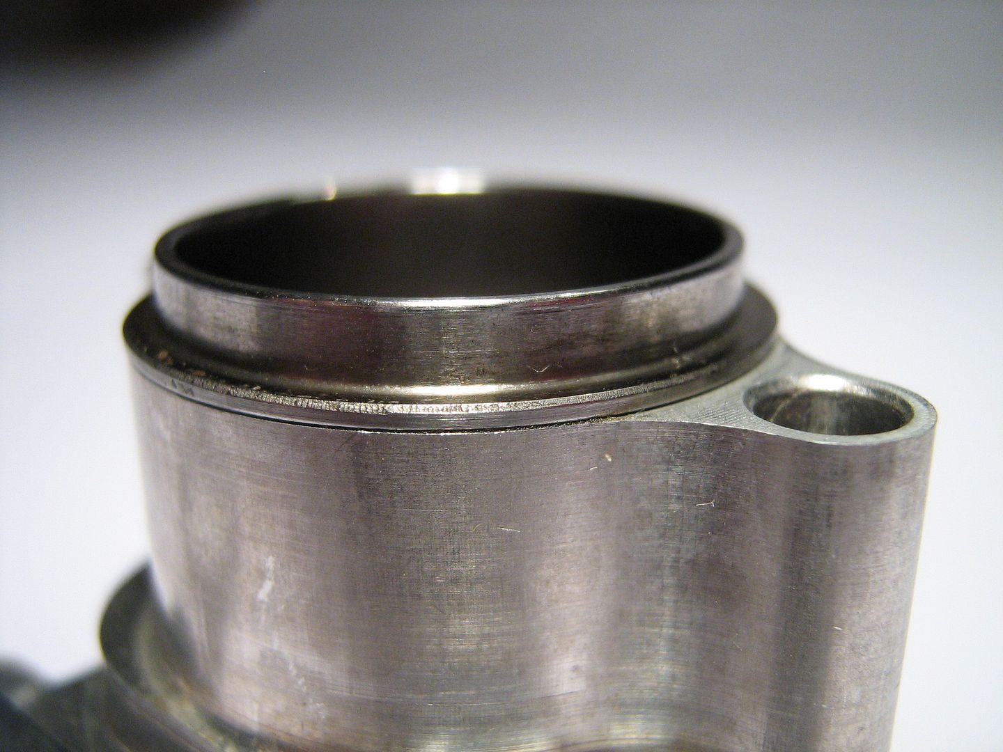
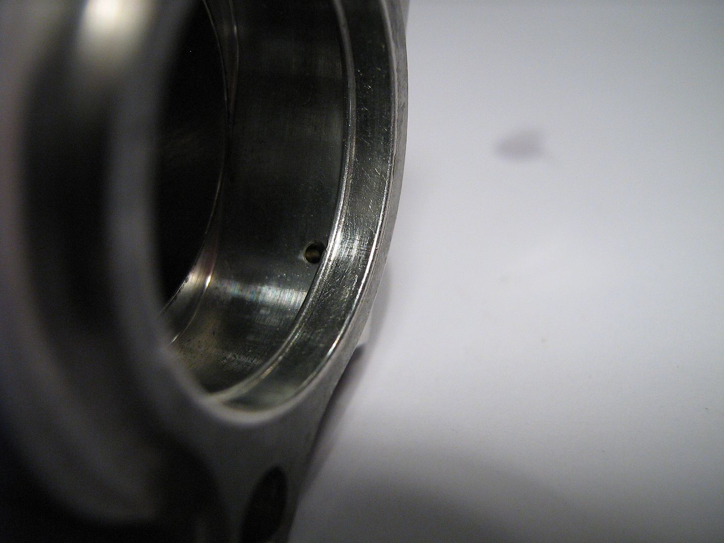
Side of assembly, showing bore liner retainer ring, this gets held on with main assembly to head fixing screws,
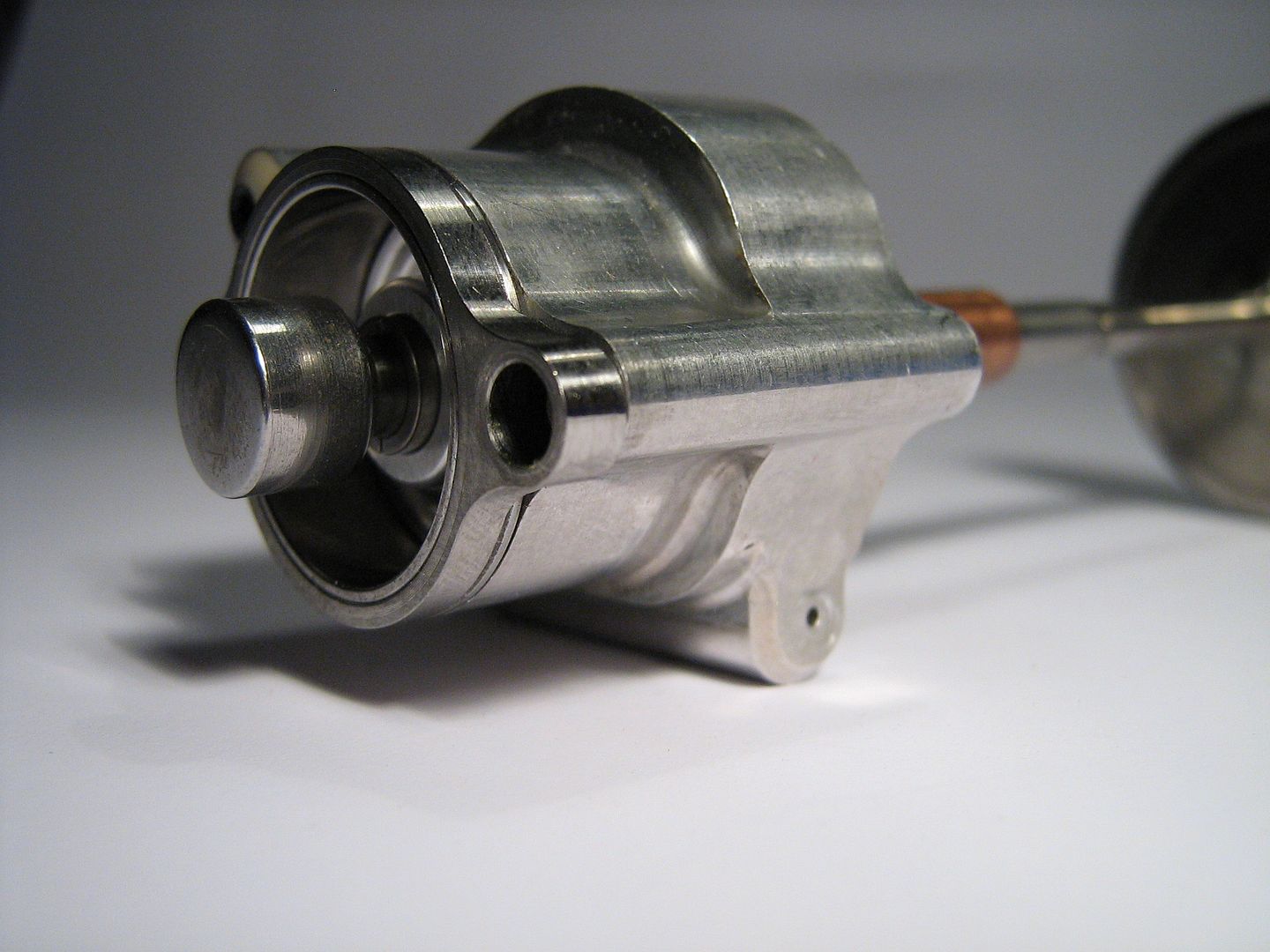
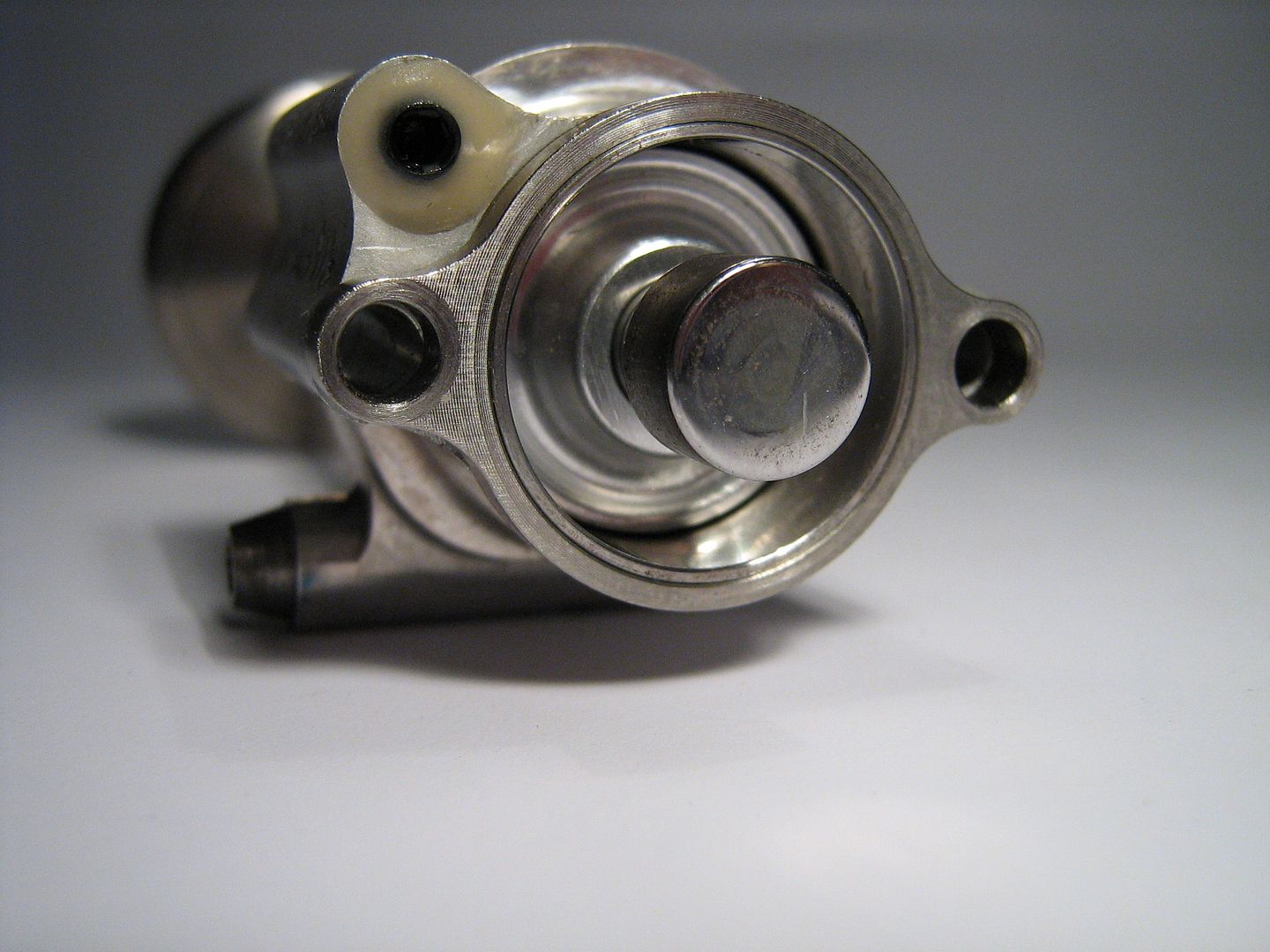
You can just see the top outer ring of steel bore liner and how its held down with retainer ring, take note too of the over pressure bleed drilling exiting relief valve area,
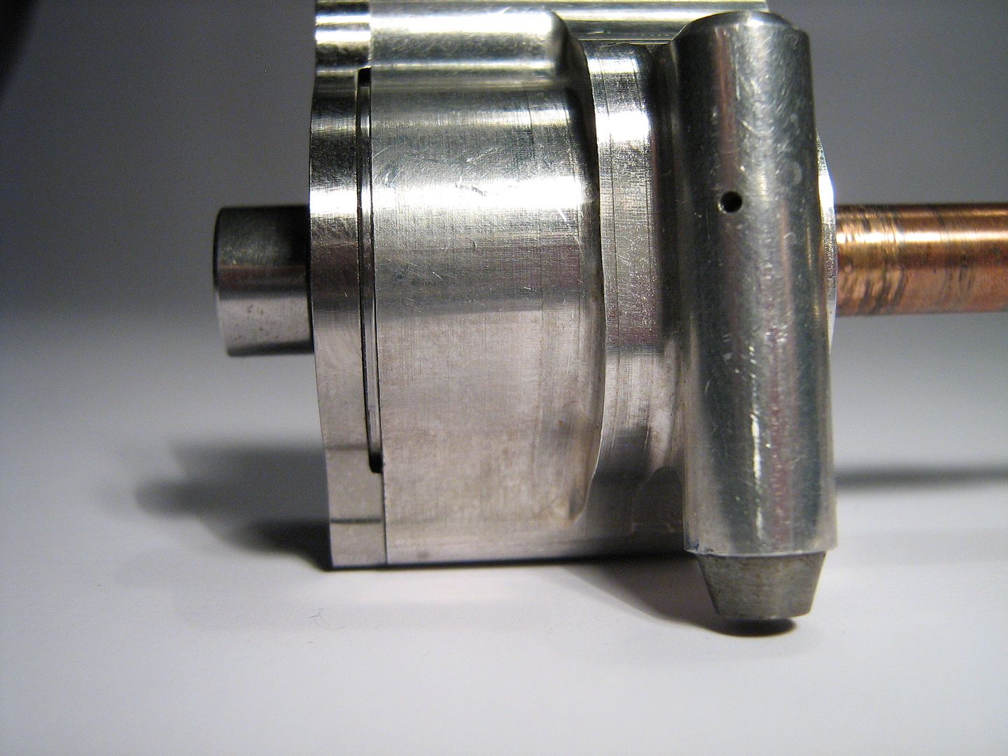
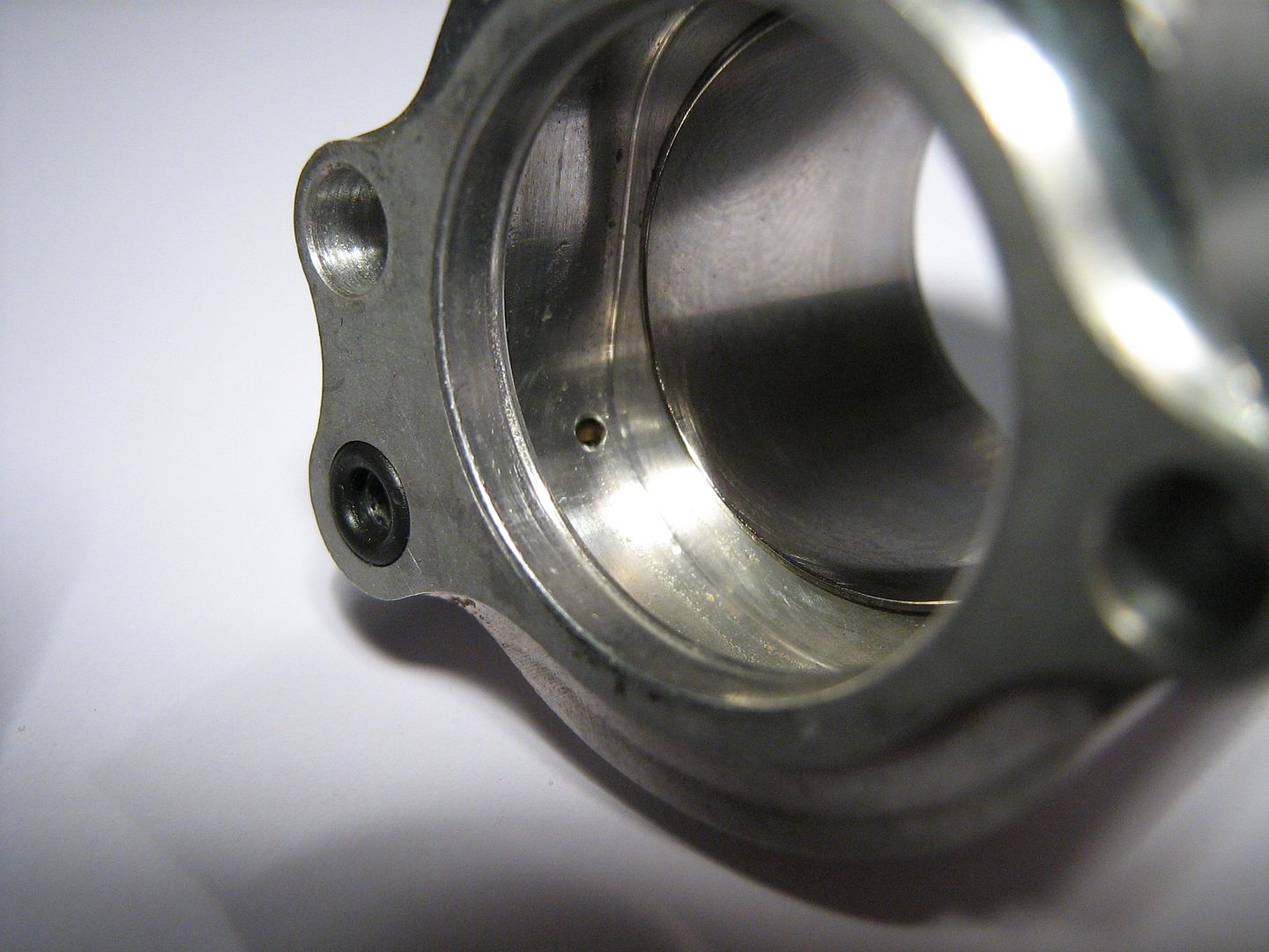
Again, the relief valve drilling and cap screw - under this screw is a spring and small valve seat - this controls over pressure under pneumatic piston - opening in over pressure conditions and bleeding off excess Nitrogen,
Now lets start to strip down the Pneumatic Valve Assembly and discuss each component,

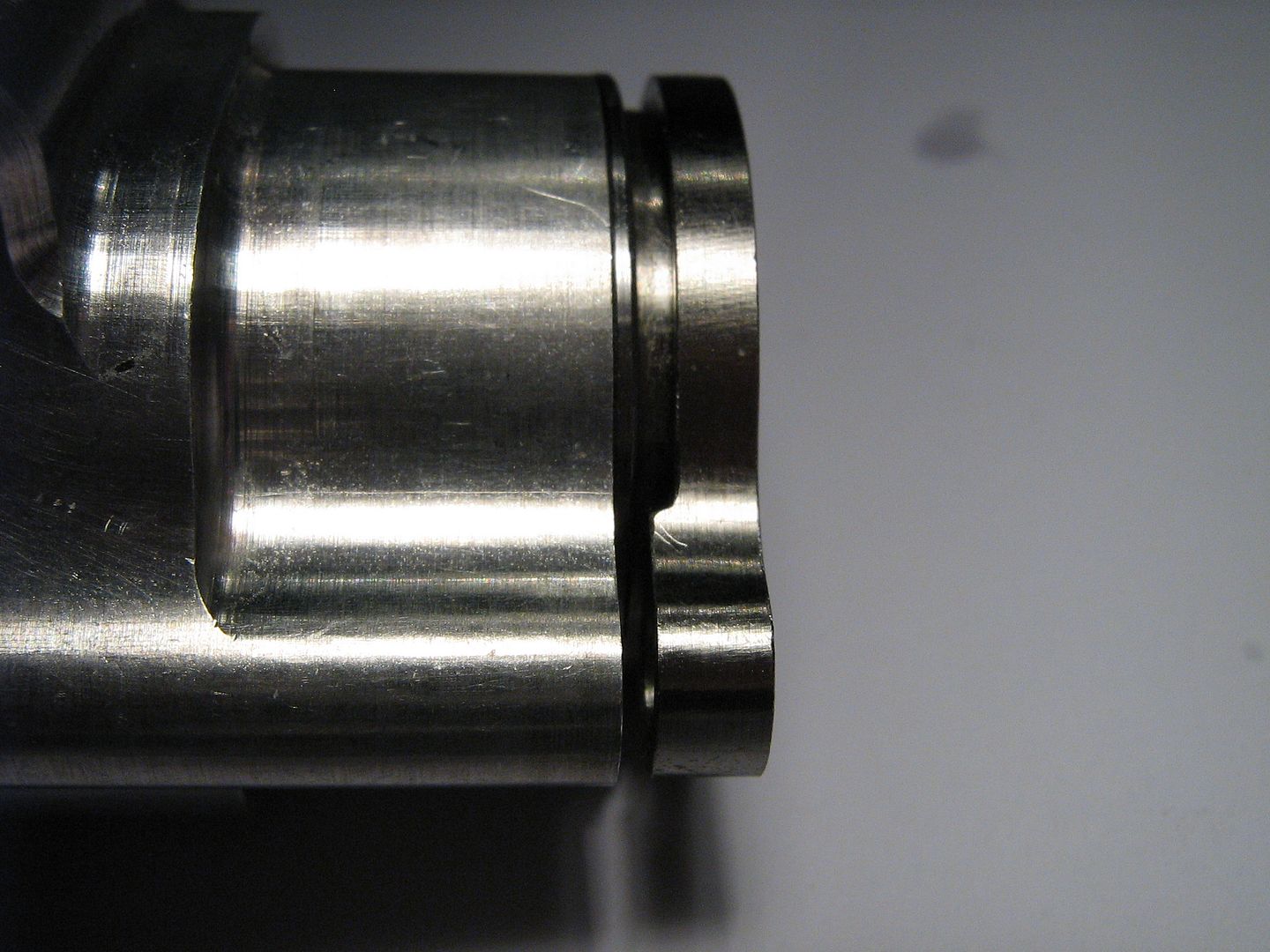
The piston and seal is a pretty tight sliding fit in the bore,
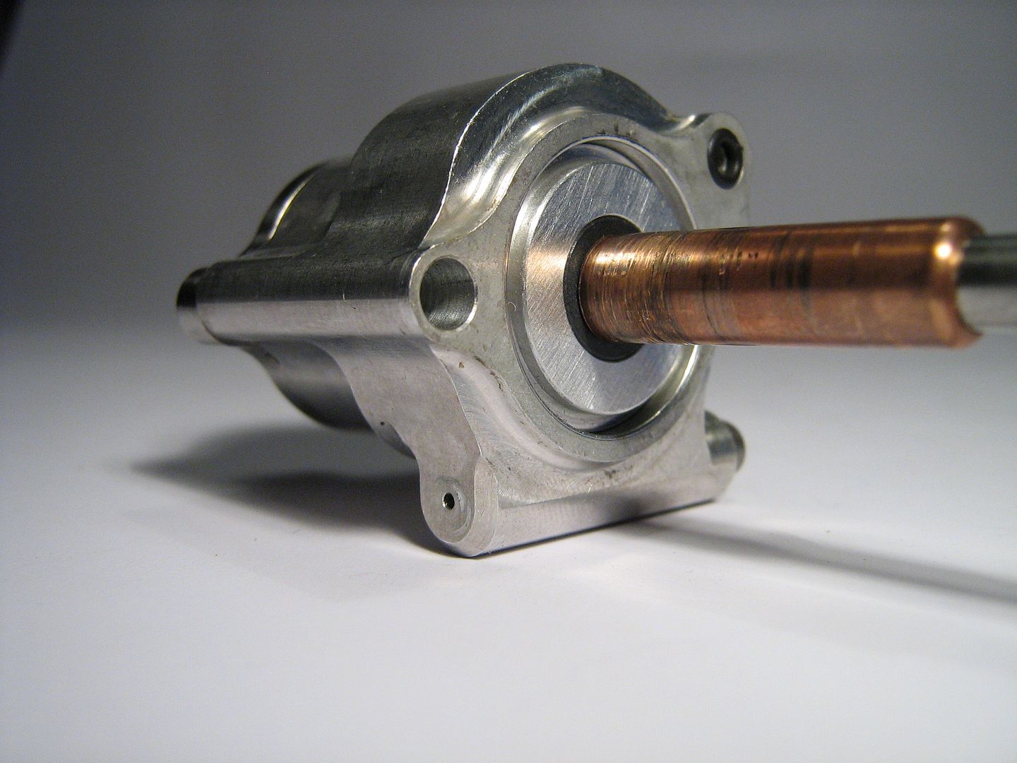
With the reciprocating parts removed it is now easier study the main body, below the bore liner retainer is withdrawn,
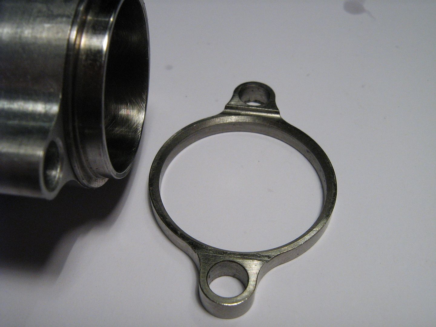
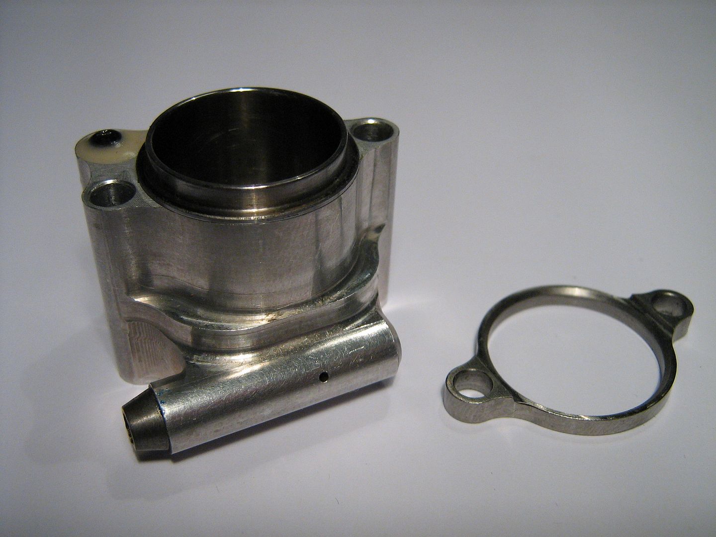
Since the main body is cnc machined aluminium(tested/confirmed) it is then fitted with a steel liner sleeve which is pressed in. Given that aluminium expands more that steel I'm guessing they added the retainer above ring for added security.
The steel bore liner can clearly be seen as a separate part below,
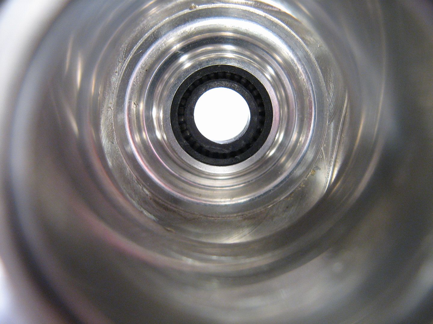
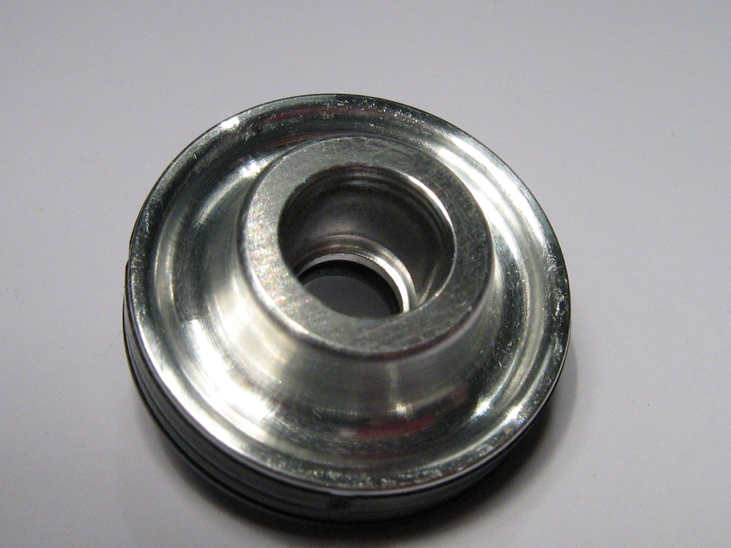
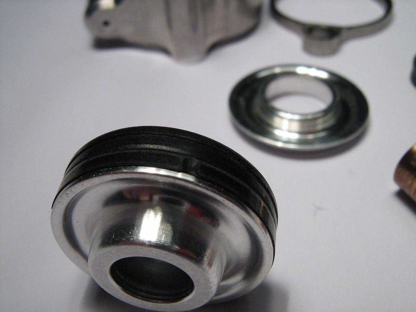
Looking at the bottom of part the lower disc can now be removed - take note of the o-ring groove mentioned above,

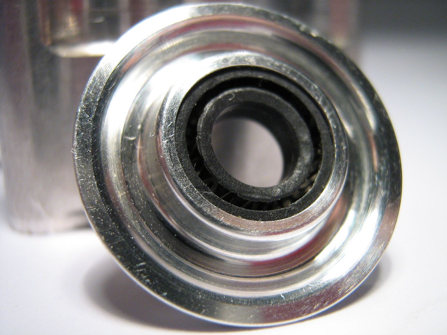
A view from inside before removal,
Removed, lower side pictured - faces onto head, stem air seal in middle,
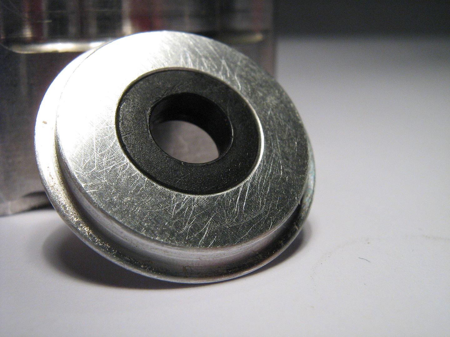
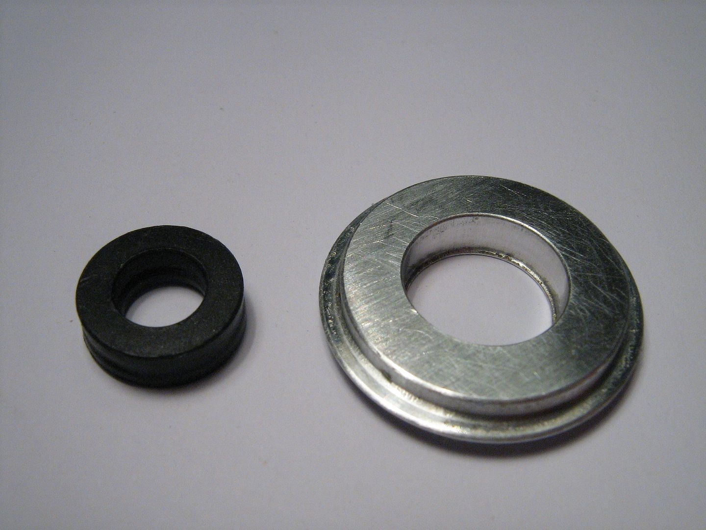
Top side of disc, worth taking note of seal orientation, the air pressure forcing seal out and against valve stem,
The seal removed, the seal is quite hard and I would suspect something by Parker and Graphite filled PTFE, - spring energized. It is also now apparent that the stiction caused by the stem seal, and also the main piston seal is enough to prevent the valve from dropping when shutdown, thus doing away with any form of weak spring that was in the past used to prevent valve drop.

Top of stem adjacent to seal in normal operating conditions,
A small lip prevents disc from rising off head face and into area under piston, take note also of drilling out to relief valve,
The air in drilling too - tapping into the vertical drilling which gets its supply from head face where the assembly mounts onto,
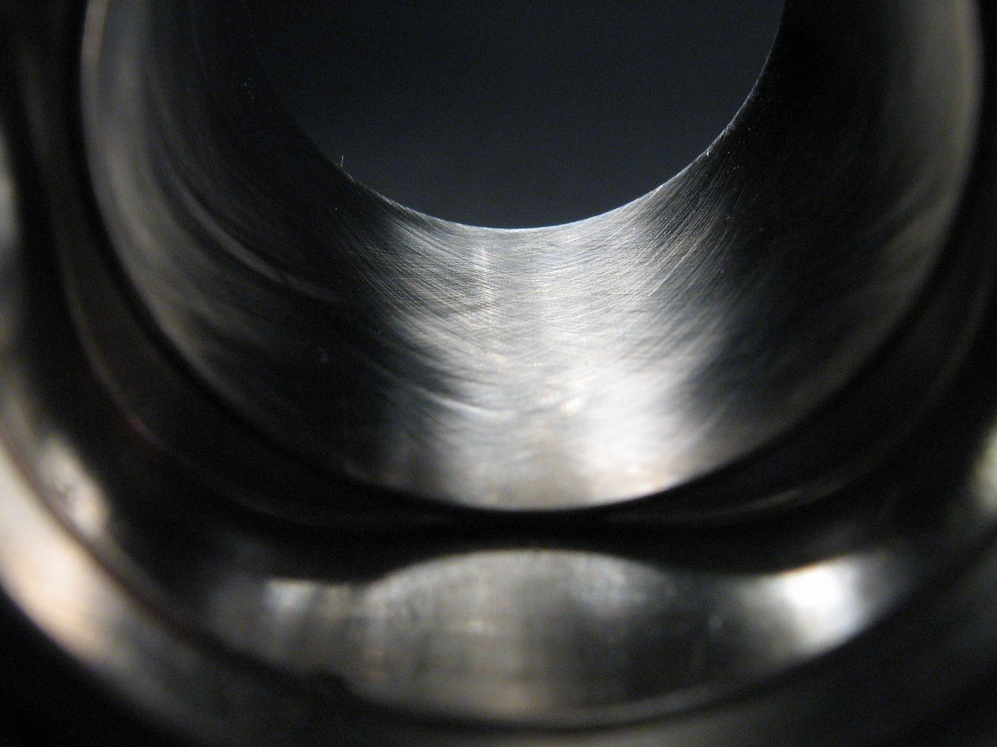
A shot of the cross hatch pattern on steel liner wall resulting from honing, the hatch pattern encouraging oil retention much like a normal engine cylinder. From looking at it the steel liner material seems to be a high chrome type tool steel type so as to prevent corrosion. It is worth noting too that in the past much r+d has be carried out in terms of plating aluminium style pneumatic assemblies - even teflon impregnation of the anodic film. Here they used a more traditional steel liner, albeit a very thin one,
Minimal liner thickness, steel is heavy and it is also 'a high up position' on the engine in terms of center of gravity. They have also lightened the aluminum body internally as much as possible by milling out all excess material at the base of liner,

The pressure relief valve and associated parts,
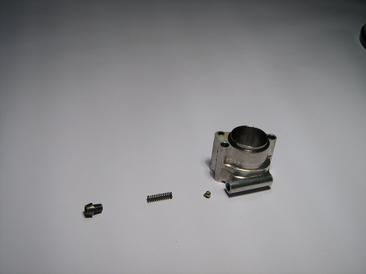
The actual valve being a steel ball in what is probably an aluminium bronze locator,
There is also an aluminium bronze seat deep inside the relief valve drilling/housing which the ball seats on.
That concludes the main F1 Pneumatic Valve Assembly Body.
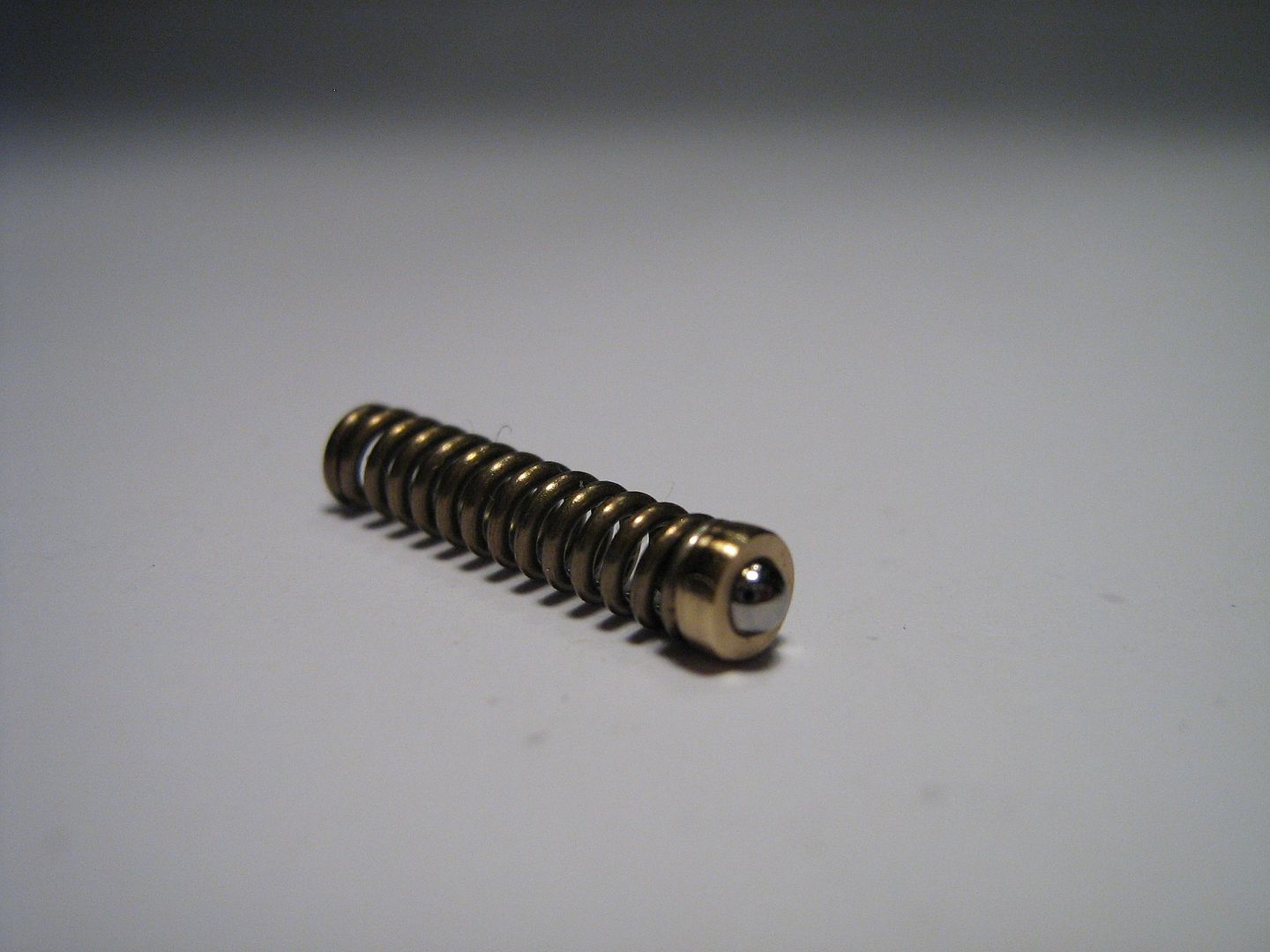
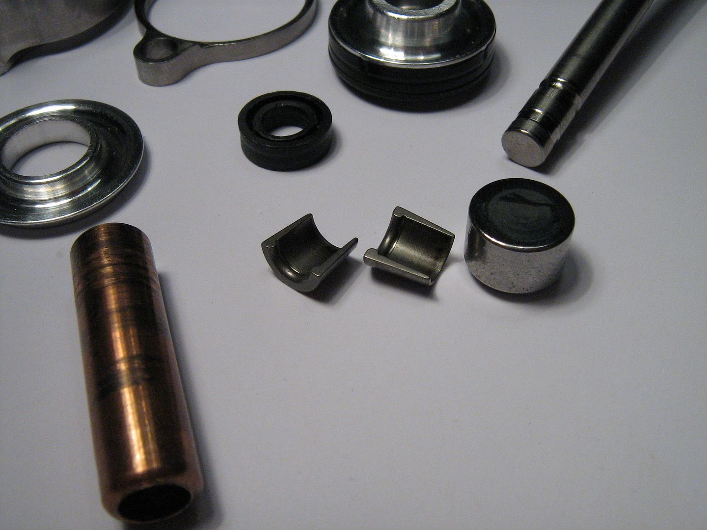
Onto the piston, lash cap, retainer-piston, and collets/cotters pictured below,
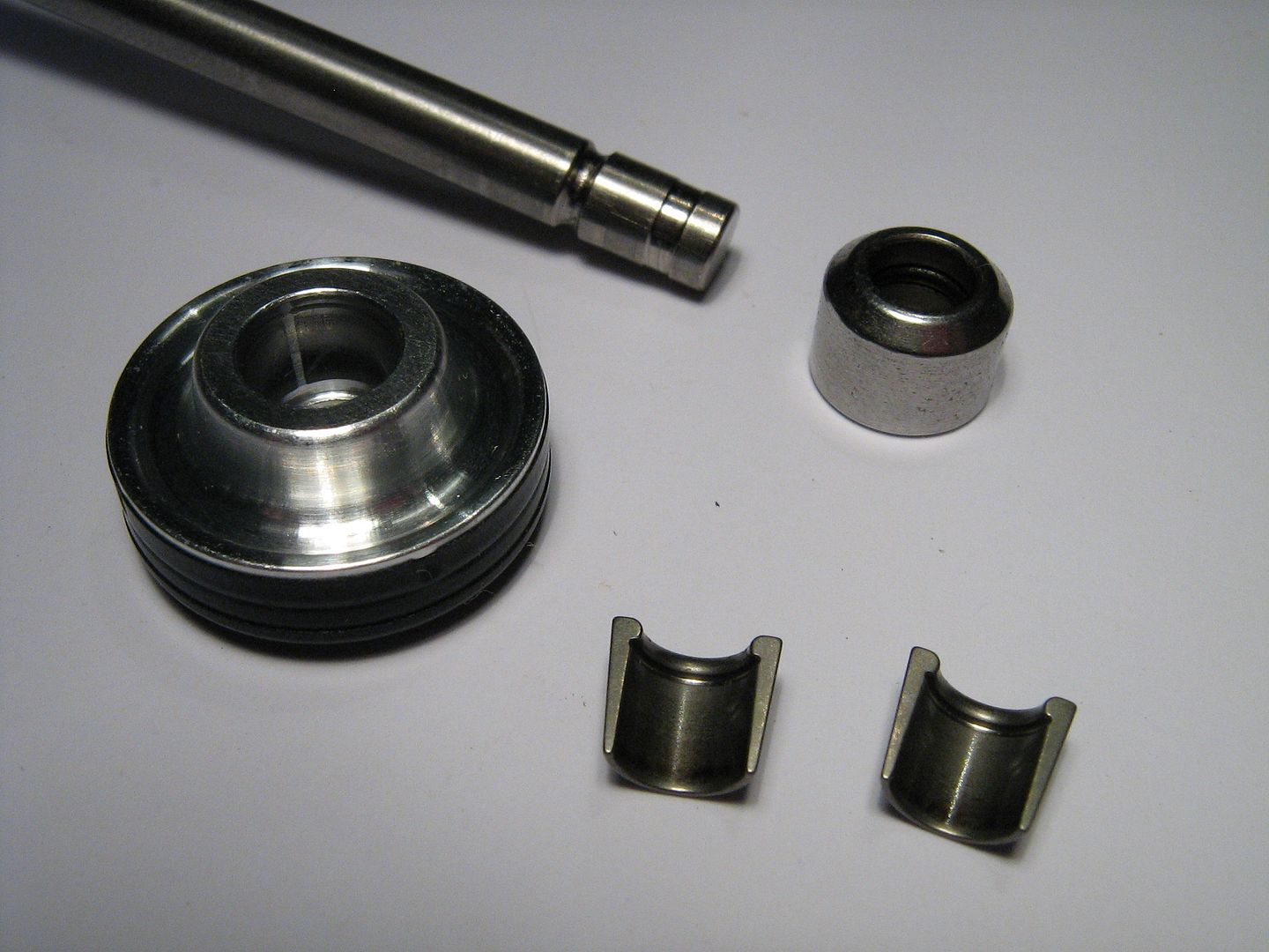
There is nothing too unusual about this layout - the collets/cotters not unlike any modern parts. The lash cap locates onto valve and is kept from falling off by an internal snap ring within the lash cap,
The collets fit snugly on the valve stem,
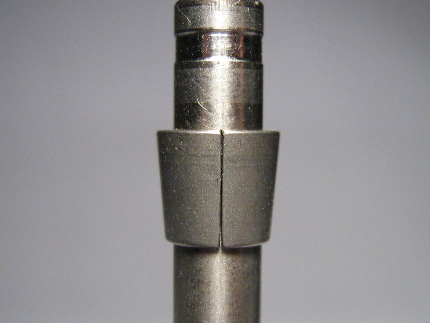
And locate as they normally do into the retainer-piston,
The lower side of the retainer piston contains an o-ring with is a snug fit on the valve stem - thus sealing off any air from exiting here,
Fitted,

Lash cap fitted,
The piston retainer cross-section below, notice again a spring energized graphite filled PTFE seal - piston is aluminium and all excess material removed for lightness - keep in mind this has an approx stroke of 13.5mm, and does so 340 odd times a second!
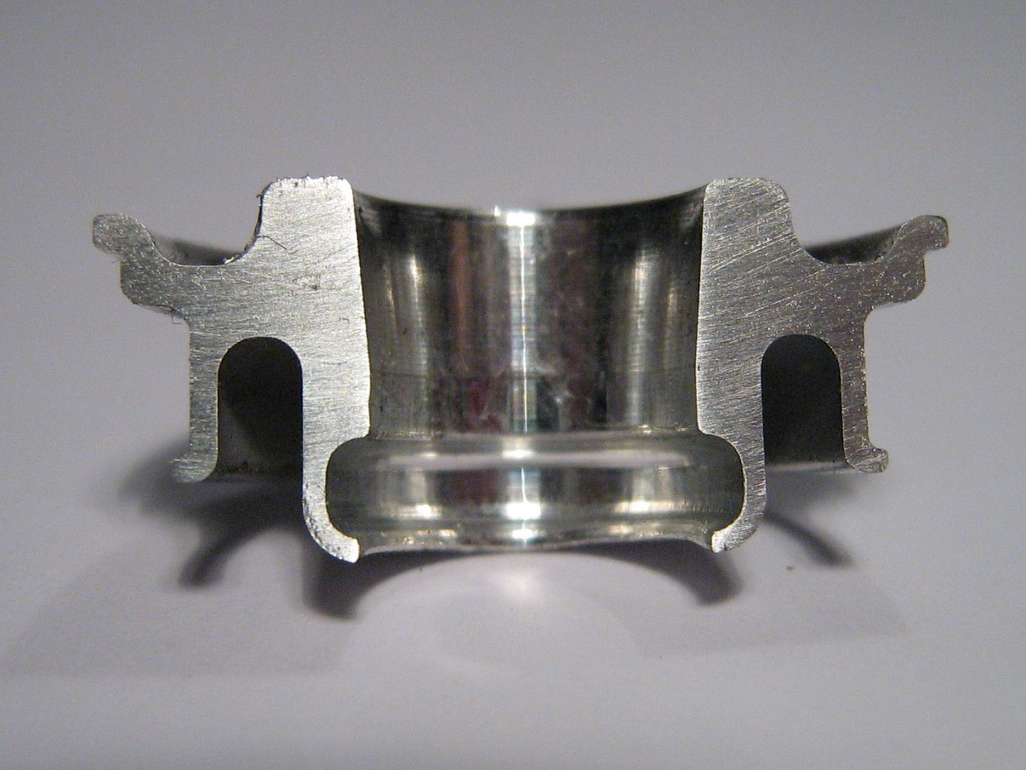
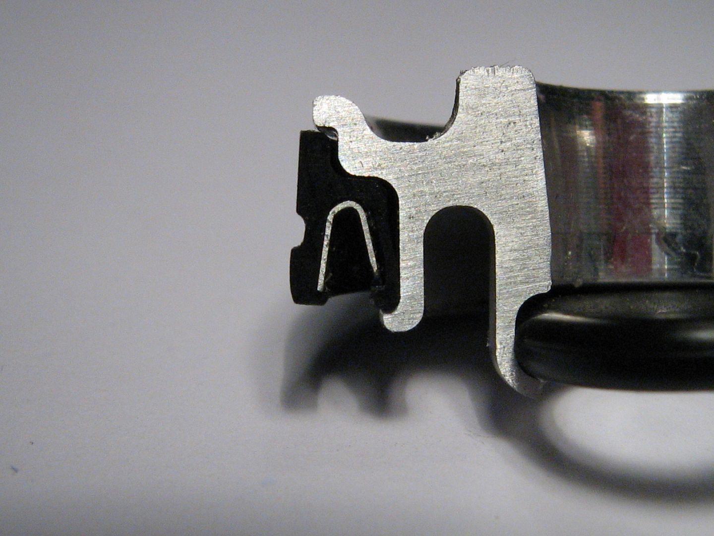
Three small grooves on the top edge of piston seal allow some cam tray oil mist to make its way onto seal lip/liner interface,
With all of the above in mind I hope the thread and information here has helped everyone from Casual Viewers, Enthusiasts, F1 fans, Engineers, Designers, Students, and Teachers Worldwide - If you know anyone whom you think would like to see it please share this link.
All pictures are backed up and on prepay hosting so they are not going to vanish anytime soon - hopefully now there is no doubt as to what a modern day 20,000rpm Formula One Pneumatic Valve Spring Assembly actually looks like inside, and how it all fits together.
All the Best,
Brian Garvey.