2 stroke thread (with occasional F1 relevance!)

All that has to do with the power train, gearbox, clutch, fuels and lubricants, etc. Generally the mechanical side of Formula One.
manolis
107
Joined: 18 Mar 2014, 10:00

Re: 2 stroke thread (with occasional F1 relevance!)

Post

Hello Uniflow.

Quite relative to the cracked cylinders and the thermal issues in aviation engines, are the issues (cracks, melting, overheating, scuffing, wear of cooperating parts) in the bridge of the exhaust port in several 2-stroke engines (water cooled or air cooled).


QUOTE from the page 136, post #2027 in this thread:


UtahTrailRide:
"Can someone explain to me what the deal is with drilling pistons on the exhaust side. I've heard the CR125 needs the piston drilled but I sure didn't in my last rebuild. Now I'm all paranoid I'm gonna shred something on the hot side."


ChrisLPD:

"OK, this is an old-school 2-stroke engine builder trick Utah,...but that one that works VERY Well! The idea is that the exhaust port bridge in the 2-stroke is a necessary evil. It is the one fault of the efficiency of a tuned 2-stroke engine. Its necessary because it acts as a land for the rings to run against as the slipper piston passes the exhaust port on its stroke to keep the ring compressed. It’s the evil because it’s the absolute hottest part of the motor and the absolute MOST suseptable to cylinder failure or nikasil plating damage for 3 reasons…

1. It is the thinnest section in the combustion chamber and can not dissipate heat. (Imagine taking a torch and heating the entire surface of a sewing needle. If you heat the needle’s eye, the shaft, and the point evenly, which part glows red first? The needle point does because it is the thinnest surface area that can not dissipate the heat).

2. All of the expanding burning hot gasses must pass by it. (Physics of Convection Dynamics)... (Imagine taking that same blow torch and blowing the flame evenly thru the center of your cylinder. It heats up in 360 degree radiation of the heat source. Now focus the flame onto one part of the cylinder. In addition to the heat from thermal radiance, the surface contact point heats up dramatically hotter because of the convection (movement) of the hot expanding gas molecules are bombarding and moving around it. Same thermal convection effect as the hot expanding combustion chamber gasses bombarding and having to move around the exhaust bridge.)

3. In lieu of both of the above critical faults, the exhaust bridge is NOT encompassed by the water jacket to get cooled


Most cylinder failures in a properly jetted and sealed 2-stroke with good fuel and lubrication are on the exhaust bridge because it gets so damned friekin hot. This is especially true of plated cylinders where you first start to see the plating flake off around the exhaust bridge. Drilling the the piston is MASSIVE insurance against this failure from the bridge warping, cracking, or flaking its plated coating. This was done by numerous factory teams and engine builders in the good'ole days before MX had cams, valves, and timing chains. This was when the manufacturers wanted to sale thumpers and pressured the AMA to establish the rules that a thumper was allowed twice the displacement to be "Fair" against the oil burners.


This is how its done...When I set up a 2-stroke, I use set-up dye. An easily removable (wipe-off) acrylic-like paint that you can spray on a part to visually inspect the wear and contact areas during motor building. I spray the dye on the front of the piston (exhaust side) and allow it to dry. I then install the piston on the wrist pin (without the rings) and lightly seat the cylinder down on it.


Once I have the cylinder lined up and seated, I look thru the exhaust port (open exhaust port with no pipe), I cycle the crank (via kick starter) until the bottom ring land passes approx ½ inch above the top of the exhaust port into the compression/combustion chamber. Using an etching tool I lightly trace both the outer left and right sides of the exhaust bridge into the set-up dye on the piston, and then disassemble.


Now with the piston removed I can see where the exhaust port bridge is in the etchings of the dye and I find the center vertical axis between these two etchings. This is the center of the exhaust port bridge. Starting ¾ of an inch below the ring land, I drill two .050 holes vertically (one on top of the other) about ½ inch apart down the center axis between the two vertical left and right marks.


The idea concept is to allow the positive pressure in the crank case (on the pistons downward stroke) to mist just a fine little amount of the cool, raw fuel/air mix onto the exhaust bridge thru the piston holes each time the piston passes the bridge. The cool, raw fuel mix acts as a cooling agent and will surprise you by how much this little trick will drop the temp of the thin little exhaust port. At 6000 RPM’s the critical heat temp on that thin little exhaust bridge is getting misted and cooled with fuel and intake air 100x a second!


Some will say this looses horsepower, I don’t believe so as long as you line the holes correctly and mist the center axis of the bridge and not vent your positive crankcase pressure out of the open exhaust port. Even if does, the loss is very, very, very minimal…but IT WILL SAVE YOUR $400 plated cylinder.


As frdbtr pointed out… This is a commonality of Wiseco recomendation in SOME of their piston kits that most people don’t read. (Some applications do not use a single port exhaust bridge). I am not familiar with the other Wossner brand he named, but wiseco recommends it because IT DOES WORK and their pistons are FORGED instead of cast and do not lose integrity by drilling the holes in the piston wall.


A Note about OEM and cast pistons… The same cooling effect would be benefited from an OEM or any other piston. It’s not often recommended for cast pistons because the “sand-cast” piston will weaken at the metallurgical level when you drill holes in it unless you stress relieve and re-harden it.


Please, please, consider all of the above My Opinion Only,... but as an educated opinion I have been building cast-iron and nikasil 2-stroke motors for 25 years and I have yet to have a cylinder failure of the exhaust bridge since I learned this from World Champion Melvin Cooper (Cooper Company Machine and Racing) building 2-stroke Hydroplane racing engines back in my twenties."


END OF QUOTE


QUOTE from http://www.millennium-tech.net/pistonTrouble.php


Image

EXHAUST BRIDGE SEIZURE
Piston seizures can occur at the center exhaust-bridge on a delta-shaped port, or the sub-exhaust bridges on a triple port design. The exhaust bridge is the hottest are of a 2-stroke cylinder and the ring pressure is at its peak because the bridge’s surface area is so small. Seizures happen for many reasons but the most common are 1) Lack of lubrication 2) Too lean jetting or air leak 3) Coolant over-heating 4) Not enough bridge relief 5) No oiling holes in the piston over-lapping the exhaust bridge.


END OF QUOTE


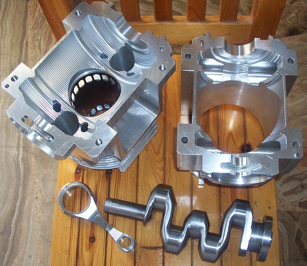
In the PatATE each bridge has not just two tiny holes to cool down it; it has all the fresh cool air / mixture to pass around the bridges to cool down them.

Image


Reasonably, the temperature of the bridges of the PatATE can be about half of the temperature of a conventional 2-stroke exhaust port bridge.

END OF QUOTE


The substantial reduction of the peak temperatures in the 2-stroke engine means a lot in terms of reliability, of lube specific consumption, of clean exhaust, of TBO etc.


Combined with the asymmetric exhaust, with the asymmetric transfer:

Image

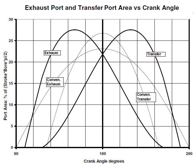
and with the asymmetric intake (without reed valves or conventional rotary or drum valves):

Image

the PatATE 2-stroke seems a serious competitor for the 4-stroke engines.

Thanks
Manolis Pattakos

Pinger
9
Joined: 13 Apr 2017, 17:28

Re: 2 stroke thread (with occasional F1 relevance!)

Post

Now plot the pressure differential driving transfer flow on to the above - and realise you will need a blower.

BTW, rubber belted CVT slips when wet. It'll be a brave cyclist that risks his genitalia standing on the pedals on a rainy day...

User avatar
henry
324
Joined: 23 Feb 2004, 20:49
Location: England

Re: 2 stroke thread (with occasional F1 relevance!)

Post

Pinger wrote:
03 Aug 2017, 15:19

BTW, rubber belted CVT slips when wet. It'll be a brave cyclist that risks his genitalia standing on the pedals on a rainy day...
Perhaps a wise cyclist will enclose the drive train?
Fortune favours the prepared; she has no favourites and takes no sides.
Truth is confirmed by inspection and delay; falsehood by haste and uncertainty : Tacitus

uniflow
36
Joined: 26 Jul 2014, 10:41

Re: 2 stroke thread (with occasional F1 relevance!)

Post

I say again manolis, make one and show us. pretty pictures mean nothing.

Pinger
9
Joined: 13 Apr 2017, 17:28

Re: 2 stroke thread (with occasional F1 relevance!)

Post

henry wrote:
03 Aug 2017, 21:00


Perhaps a wise cyclist will enclose the drive train?
More weight, frictional seals.

Anyway, this isn't a CVT as the Continuous part has been sacrificed for rider control and as that removes the self tensioning aspects it is doomed to high clamping loads and excessive friction.

manolis
107
Joined: 18 Mar 2014, 10:00

Re: 2 stroke thread (with occasional F1 relevance!)

Post

Hello Uniflow.


You write:
“I say again manolis, make one and show us. pretty pictures mean nothing.”


However,
the meaning of a technical discussion like this one,
is by far different than:
“make one and show us”.


Someone proposes a new (or “new”) technical solution; the rest forum members can read, understand (the “pretty pictures” mean a lot in this stage) and think.

Then, if they like so, they write down their justified (or not) technical objections / thoughts.

It is a “win-win” process.


The guy who proposes the new, or “new”, technical solution is asking for “independent third party” objections and opinions in order to decide either to abandon the idea, or to proceed with it (by making prototypes, by testing them etc).

He is also presenting his idea to “whom it may concern”.


By the way:

Seven months ago, at page 87, posts #1296-1297, a discussion remained unfinished, even if the “make one and show us” was the case:


The PatOP pattakon engine is real:

Image

from metal:

Image

Image

works on Diesel fuel:

(youtube video: https://www.youtube.com/watch?v=2ByEgfTTq1I )

and concentrates unique characteristics:

Bore: 79.5mm
Stroke: 64+64=128mm
Displacement: 635cc
Compression ratio: 17
Scavenging pump bore: 130mm (1.34 scavenging ratio)
Total engine height: 500mm
Total engine weight (without the flywheel): less than 20Kp

It is an:
opposed-piston,
two-stroke,
single-cylinder,
single-crankshaft,
full-balanced (vibration free),
cross-head,
direct-injection Diesel engine,
with built-in "volumetric" (for a wider rev range and flat torque curve) scavenging pump,
with four-stroke-like lubrication,
and with some 35% as compared to the conventional, or some 20% as compared to the Junkers-Doxford and to the OPOC of EcoMotors, additional time for the injection and combustion of the fuel.


It is also patented,
which means that some experts / specialists in the field (examiners in big patent offices like the USPTO, the UK-IPO etc), after searching all the prior art, they decided the idea in question is new, it has inventive step and is industrially applicable.


Worth to mention here:

The only things from the market used in the above PatOP prototype engine are the piston rings (from a VW TDi), the plain bearings (from a BMW 1600cc) and the fuel injection system (it is from a cheap Chinese 4-stroke electric generator).
All the rest parts were made either from 7075 aluminum billet (if I remember correctly, we started with 54Kg (120lb) aluminum for the casing) or from Orvar Supreme steel (crankshaft, connecting rods).


Enjoy how nice, smoothly and clearly it runs on Diesel fuel, standing free on a desk. We talk for big single-cylinder direct injection Diesel engine.

The prototype works as the theory predicts.

However, the important is the theory, the theoretical solution proposed; not the working prototype.

Please do read, at the page 107, post #1601 of this thread, what the professor Rui Chen of the famous Loughborough University - UK did (“Quasi-constant volume spark ignition combustion”, presentation in the International Engine Expo 2009, Stuttgart Germany) in order to achieve the longer piston dwell of the OPRE and PatOP engines.


So, if you still don’t like to comment on the PatATE idea because the “make one and show us” requirement is not yet fulfilled,
you can alternatively write your technical objections / thoughts about the PatOP.

Thanks
Manolis Pattakos

manolis
107
Joined: 18 Mar 2014, 10:00

Re: 2 stroke thread (with occasional F1 relevance!)

Post

Hello Pinger.

You write:
"Now plot the pressure differential driving transfer flow on to the above - and realise you will need a blower."


The working gas has inertia.

And requires time in order to start moving in a passageway.
And more time to reverse direction when it already flows in a passageway / pipe.


Here is the timing plot:

Image

of the OS18TZ model engine (more at http://www.pattakon.com/tempman/osmz211 ... cnitro.pdf )

Dont't look at the 30,500rpm of the maximum power. The mean piston speed is only 15m/sec, i.e. this model engine runs at normal speeds, for its size.

The intake closes 60 degrees after the TDC because, despite the significant reduction of the crankcase volume at 60 degrees after the TDC, the inertia of the gas (at the revs the engine runs) is so strong that the gas continues entering through the drum valve in the crankcase.

Here is the timing plot of several old Ducati's:

Image

The intake valves of several 4-stroke Ducati engines close at 90 degrees after the BDC in order to maximize the quantity of trapped gas in the cylinder at the revs the engine is to operate.

And here is the same plot with the curves of the PatATE 2-stroke and of the Yamaha RD350LC added:

Image


If the PatATE 2-stroke engine is to work at 1,000rpm, then yes, such a timing:

Image

will allow a big portion of the air-fuel mixture to return to the crankcase (important: not to be lost towards the exhaust, as happens in the conventional two-strokes, but to return to the crankcase) and be used in the next cycle, just like in the Atkinson-Miller engine of the PRIUS of Toyota.

But as the revs increase (say, at 12,000rpm? at 15,000rpm?) the time for passing the gas from the crankcase into the cylinder is so small that the transfer should stay open for even longer than the above plot shows.


The PatATE brings a totally different solution in the 2-strokes.
Among others, the breathings gets more similar to that of the 4-stroke engines having big overlap than to the breathing of the conventional 2-strokes.

Thanks
Manolis Pattakos

User avatar
henry
324
Joined: 23 Feb 2004, 20:49
Location: England

Re: 2 stroke thread (with occasional F1 relevance!)

Post

Pinger wrote:
04 Aug 2017, 06:50
henry wrote:
03 Aug 2017, 21:00


Perhaps a wise cyclist will enclose the drive train?
More weight, frictional seals.

Anyway, this isn't a CVT as the Continuous part has been sacrificed for rider control and as that removes the self tensioning aspects it is doomed to high clamping loads and excessive friction.
The additional weight and friction would be small and easily compensated for by the ability to be in a "better" gear, one that is more comfortable and human efficient.

Your reading of the C in CVT is different from mine. I believe it means continuously. That is anybavailable ratio, between fixed upper and lower, can be selected rather than in a series of steps.

Being C does not require some agent other than the user to vary those ratios. Even so Manolis has suggested a mechanism that could be used to do the ratio change for the rider.

I don't see why the clamping loads should be higher than those imposed by axial movement of the pulley halves.
Fortune favours the prepared; she has no favourites and takes no sides.
Truth is confirmed by inspection and delay; falsehood by haste and uncertainty : Tacitus

manolis
107
Joined: 18 Mar 2014, 10:00

Re: 2 stroke thread (with occasional F1 relevance!)

Post

Hello Pinger.

You write:
"BTW, rubber belted CVT slips when wet."

When wet, the coefficient of friction between the road and the rear tire is reduced, too.


You write:
"More weight, frictional seals."

The IGH's (Rohloff SpeedHub, Alfine 11 Shimano etc), and the NuVinci CVT, all do need good sealing because they use oil to lubricate the several parts inside the cover, and pay relative friction losses for both, the sealing and the lubricant.

They also add weight (nothing to do with the weight of a plastic cover around the PatBox (which, after all, is not really necessary).


You also write:
"Anyway, this isn't a CVT as the Continuous part has been sacrificed for rider control and as that removes the self tensioning aspects it is doomed to high clamping loads and excessive friction."

Yet it is a real CVT (Continuously Variable Transmission).

Because the bicycler can select from a continuous infinity, by displacing the lever.

The high clamping loads is a characteristic of all V-belt scooters CVT's. And there are many millions of them on the roads.

The efficiency plots in the previous posts say that the best gear-trains used in the modern bicycles arenot so good regarding their real efficiency.


Let's see what the PatBox CVT adds to the simplest (and the most efficient at the same time) single-ratio bicycle gear-train:

The two sprockets are replaced by conical pulleys (each having its own spring to keep close its two conival pulley halves).
The chain is replaced by the V-belt.

The auxiliary belt needs not to be an elastic belt. A cloth-like-belt (say from aramid fibers):

Image

is fine and adds insignificant friction.

All the added friction has to do with the loss in the cooperation of the V-belt with the two conical pulleys.

So, the question turns to how much more inefficient, than a bicycle chain, a V-belt is, especially one that will run at low speeds (nothing to do with the V-belts in the scooters), and one which is not limited by its load carrying capacity (again nothing to do with the V-belts in the CVT's of the scooters).

As shown in previous posts, the Burgman 650 SECVT, which is based on a metallic / elastic V-belt:

Image

achieves efficiences up to 95%.


To be noted: in a PatBox CVT bicycle there isn't any "final transmission" like that of the typical scooters:

Image

Thanks
Manolis Pattakos

Tommy Cookers
617
Joined: 17 Feb 2012, 16:55

Re: 2 stroke thread (with occasional F1 relevance!)

Post

[quote=henry]......I don't see why the clamping loads should be higher than those imposed by axial movement of the pulley halves.[/quote]

just what I was thinking ..... though ....

would/wouldn't a non-CVT V belt drive with a number of discrete rigidly fixed pulley positions ('gears') have less 'clamping' ie frictional loss
the other pulley remaining fixed - and belt tension being managed by a jockey tensioner
belt tension setting could be adjusted according to rider power - this adjustment could even be automatic
(the weak or lazy rider should not suffer the tension-related friction needed to accomodate the strong or keen rider)

btw page 43 shows the Platt PIV https://books.google.co.uk/books?id=xhq ... or&f=false

manolis
107
Joined: 18 Mar 2014, 10:00

Re: 2 stroke thread (with occasional F1 relevance!)

Post

Hello Tommy Cookers.

You write:
"would/wouldn't a non-CVT V belt drive with a number of discrete rigidly fixed pulley positions ('gears') have less 'clamping' ie frictional loss
the other pulley remaining fixed - and belt tension being managed by a jockey tensioner "


It is, more or less, the same thing, and has about the same friction loss.
The only that changes is that the system stops being a CVT.

Instead of the external tensioner you describe, the PatBox CVT for bicycles has two built-in tensioners (the springs of the conical pulleys); their combined action defines the tension of the V-belt in the conical pulleys (and the over-clamping).

As for managing the V-belt tension, this can the done in the PatBox, too.

For instance, the control lever, through a linkage to the center of the rear wheel, can reduce the tension of the rear conical pulley at the longer transmission ratios.

If it is not clear how, let me know to show it by a drawing or animation.

Thanks
Manolis Pattakos

Pinger
9
Joined: 13 Apr 2017, 17:28

Re: 2 stroke thread (with occasional F1 relevance!)

Post

henry wrote:
04 Aug 2017, 08:54

The additional weight and friction would be small and easily compensated for by the ability to be in a "better" gear, one that is more comfortable and human efficient.
A ''better'' gear than one of the 21 offered by a derailleur system?


henry wrote:
04 Aug 2017, 08:54
Your reading of the C in CVT is different from mine. I believe it means continuously. That is anybavailable ratio, between fixed upper and lower, can be selected rather than in a series of steps.
Then better to cease all reference to the Manolis system as CVT. Without the(continuously variable) 'shift-out' facility, it's just a belt drive with selectable ratio - as found in a lawnmowers.


henry wrote:
04 Aug 2017, 08:54
Being C does not require some agent other than the user to vary those ratios. Even so Manolis has suggested a mechanism that could be used to do the ratio change for the rider.
The electric required to drive the change mechanism would be better deployed driving the rear wheel.


henry wrote:
04 Aug 2017, 08:54
I don't see why the clamping loads should be higher than those imposed by axial movement of the pulley halves.
Without the torque sensitivity of a CVT system's secondary clutch which via the helix increases clamping force (how the sheaves close and alter the ratio) proportional to belt pull from the primary, the secondary clutch will have to be sprung much harder to give the required pinch force and that spring rate (and pinch force) will be higher than necessary for all other scenarios. And, as the belts losses are during bending and the bending occurs between the sheaves - higher clamp forces there will reduce efficiency.

And - completely unremarked upon as yet - the rear fork will have to dismantle-able to fit the belt. Not all bicycle manufacturers are going to like that.

Pinger
9
Joined: 13 Apr 2017, 17:28

Re: 2 stroke thread (with occasional F1 relevance!)

Post

Tommy Cookers wrote:
04 Aug 2017, 12:01
henry wrote:......I don't see why the clamping loads should be higher than those imposed by axial movement of the pulley halves.
just what I was thinking ..... though ....

would/wouldn't a non-CVT V belt drive with a number of discrete rigidly fixed pulley positions ('gears') have less 'clamping' ie frictional loss
the other pulley remaining fixed - and belt tension being managed by a jockey tensioner
belt tension setting could be adjusted according to rider power - this adjustment could even be automatic
(the weak or lazy rider should not suffer the tension-related friction needed to accomodate the strong or keen rider)

btw page 43 shows the Platt PIV https://books.google.co.uk/books?id=xhq ... or&f=false
If you fix one pulley than the other will have to be nearly double the diameter to effect the same ratio range. Tensioning the belt will likely bring one belt run into contact with the other when the variable pulley is at its most open position. The inverse opening/closing of both pulleys in a CVT avoids both scenarios.

Forcing a belt down a pulley to spread the sheaves to effect a ratio change is not trivial. The force required will not be achieved by finger or thumb and removing a hand from the handlebar to pull on a lever is unthinkable - no one will buy that.

I have yet to see (never say never!) PIV used as merely a torque transmission. Their primary use is in precise speed control for process operations (eg machining work (cutting speed), production line speed control, etc).

User avatar
henry
324
Joined: 23 Feb 2004, 20:49
Location: England

Re: 2 stroke thread (with occasional F1 relevance!)

Post

Pinger wrote:
04 Aug 2017, 14:37
henry wrote:
04 Aug 2017, 08:54

The additional weight and friction would be small and easily compensated for by the ability to be in a "better" gear, one that is more comfortable and human efficient.
A ''better'' gear than one of the 21 offered by a derailleur system?


henry wrote:
04 Aug 2017, 08:54
Your reading of the C in CVT is different from mine. I believe it means continuously. That is anybavailable ratio, between fixed upper and lower, can be selected rather than in a series of steps.
Then better to cease all reference to the Manolis system as CVT. Without the(continuously variable) 'shift-out' facility, it's just a belt drive with selectable ratio - as found in a lawnmowers.


henry wrote:
04 Aug 2017, 08:54
Being C does not require some agent other than the user to vary those ratios. Even so Manolis has suggested a mechanism that could be used to do the ratio change for the rider.
The electric required to drive the change mechanism would be better deployed driving the rear wheel.


henry wrote:
04 Aug 2017, 08:54
I don't see why the clamping loads should be higher than those imposed by axial movement of the pulley halves.
Without the torque sensitivity of a CVT system's secondary clutch which via the helix increases clamping force (how the sheaves close and alter the ratio) proportional to belt pull from the primary, the secondary clutch will have to be sprung much harder to give the required pinch force and that spring rate (and pinch force) will be higher than necessary for all other scenarios. And, as the belts losses are during bending and the bending occurs between the sheaves - higher clamp forces there will reduce efficiency.

And - completely unremarked upon as yet - the rear fork will have to dismantle-able to fit the belt. Not all bicycle manufacturers are going to like that.
As I mentioned before, my experience of many years riding with regular cycle commuters is that a significant proportion don't change gear at all let alone pick from 21 in a derailleur system. A benefit of a continuously variable system is that the choices can be characterised as up-hill, flat, downhill,or some other simple choice. The NuVinci has an option to choose a cadence and it ratio shifts to maintain it. An auto shifting mechanism would definitely benefit the average commuter.

Having said which I don't think your definition of a CVT as having to be "automatic" is right. Dictionary.com has:
noun, Automotive, Machinery.
1.
a transmission, typically using rubber belts and pulleys, in which the ratio of the rotational speeds of two shafts, as the drive shaft and driven shaft of a vehicle, can be varied continuously within a given range, providing an infinite number of possible ratios.
Abbreviation: CVT.
I would need to see some figures before I could agree or disagree about the best use of electricity for power or ratio selection. My gut feeling is for the average rider ratio selection would be better.

Your point about dismantable rear forks is a good one.

Manolis has responded on the pinch force issue.
Fortune favours the prepared; she has no favourites and takes no sides.
Truth is confirmed by inspection and delay; falsehood by haste and uncertainty : Tacitus

Pinger
9
Joined: 13 Apr 2017, 17:28

Re: 2 stroke thread (with occasional F1 relevance!)

Post

henry wrote:
04 Aug 2017, 17:43


As I mentioned before, my experience of many years riding with regular cycle commuters is that a significant proportion don't change gear at all let alone pick from 21 in a derailleur system. A benefit of a continuously variable system is that the choices can be characterised as up-hill, flat, downhill,or some other simple choice. The NuVinci has an option to choose a cadence and it ratio shifts to maintain it. An auto shifting mechanism would definitely benefit the average commuter.
But an auto shifting mechanism for a belt system requires a torque sensitive secondary pulley (or else the preload to avoid belt slip is punitive to the belt) and that simply cannot work with the torque fluctuations from pedalling.

henry wrote:
04 Aug 2017, 17:43
Having said which I don't think your definition of a CVT as having to be "automatic" is right. Dictionary.com has:
noun, Automotive, Machinery.
1.
a transmission, typically using rubber belts and pulleys, in which the ratio of the rotational speeds of two shafts, as the drive shaft and driven shaft of a vehicle, can be varied continuously within a given range, providing an infinite number of possible ratios.
Abbreviation: CVT.
OK, go for manual control instead eschewing the CVT's ability to create pinch and manipulate the pulleys such that ratio change is effected and belt slippage avoided by clever deployment of rotational and torque forces.....

henry wrote:
04 Aug 2017, 17:43
I would need to see some figures before I could agree or disagree about the best use of electricity for power or ratio selection. My gut feeling is for the average rider ratio selection would be better.
..... and now ponder how to emulate a scooter CVT transmitting circa 5lbs.ft of torque with a 200lb cyclist generating 100lbs.ft torque without the belt slipping. Manipulate the force required for that from the handlebar? It'd be worse than tensioning a truck's fan belt - while simultaneously riding a bike.

Post Reply