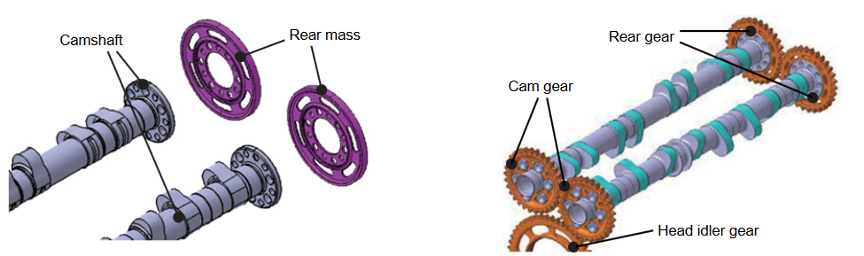
In this thread I will be unlocking a few secrets hidden within this part - The F1 Timing Gear Damper, mainly its construction, oiling, and some other features. It's from my own F1 V10 engine and is also used in the later V8 engine and one that had a 20,000rpm+ rev limit. There are two of these dampers used per engine - both driven off the crank gear - each one driving on up to the heads as shown on the V8 engine below,
(Image Courtesy of Luke_Bywater - Google Search)
If you have not read the discussion about the Timing Gear Cover from the V8 since it features briefly in this discussion it can be viewed here > https://www.f1technical.net/forum/viewt ... =4&t=26358. The v10 and v8 damper gears and timing covers are same/similar in terms of design.
The need for the Timing Gear Damper showed its head very early on back in the DFV days. Crank torsional vibrations as well as resonance in the timing gear trains at particular rpms lead to many failed valve and gear trains on the DFV so a solution was required to smooth these vibrations within the gear train. In simple terms the job of the Timing Gear Damper is to smooth out resonance which if left unchecked can quickly become destructive. As the years went by, the problem didn't go away and because of this Timing Gear Train dampers can be found in all F1 Engines today - In fact, the Timing Gear Damper below has not changed much at all in terms of design and layout since Keith Duckworth's original solution back in the 70s on the DFV. Back then it had two names over the time, "Quill Hub Damper", and "Deflection Absorber".
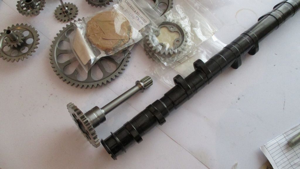
So with that in mind, onto the part itself.
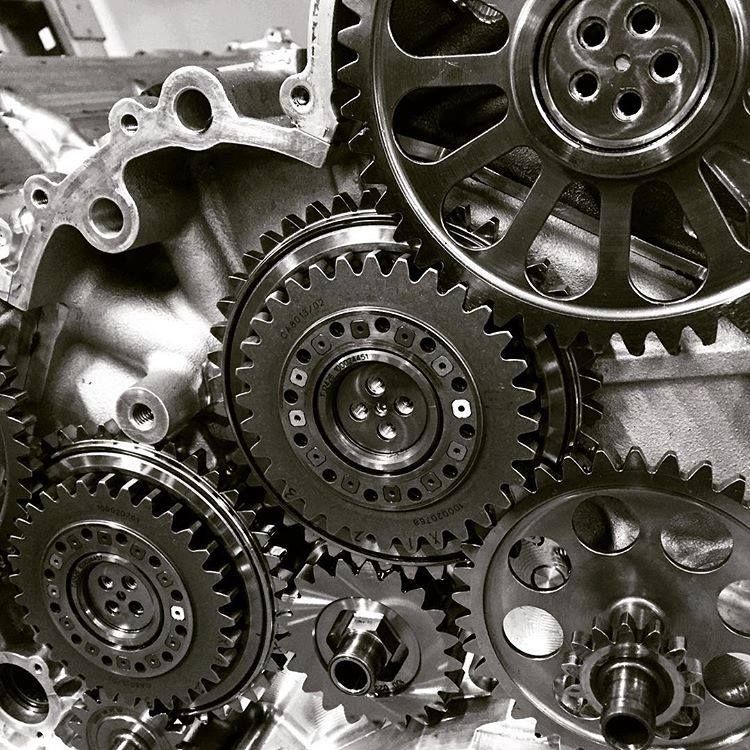
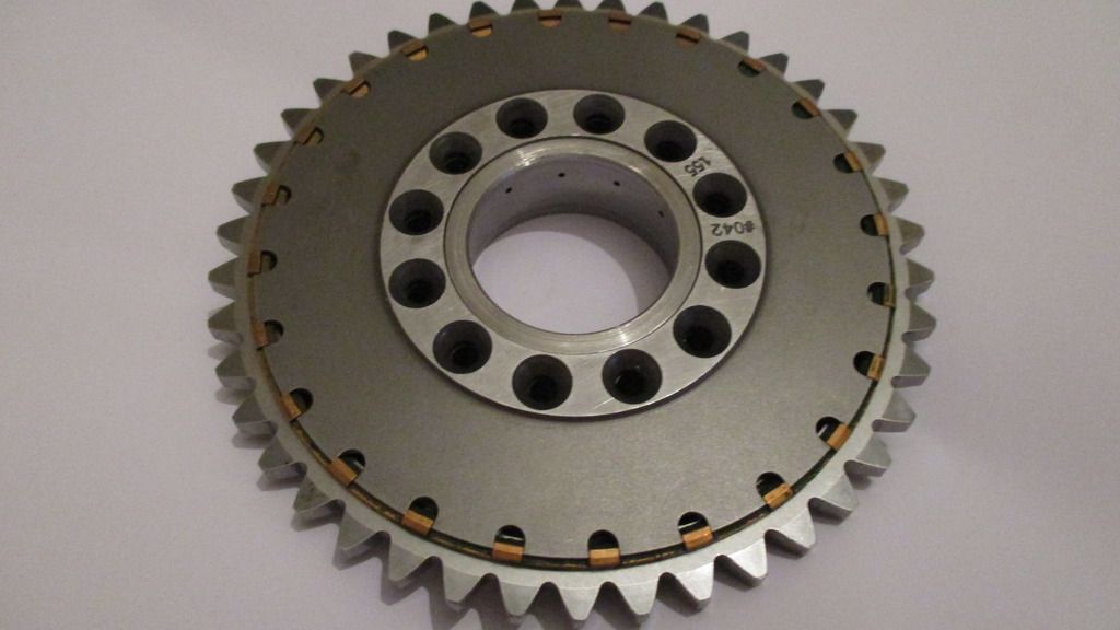
From the outside it doesn't look much,
Oil drilling's visible around central bearing - the gear as a whole held captive axially by the Timing Gear Cover,
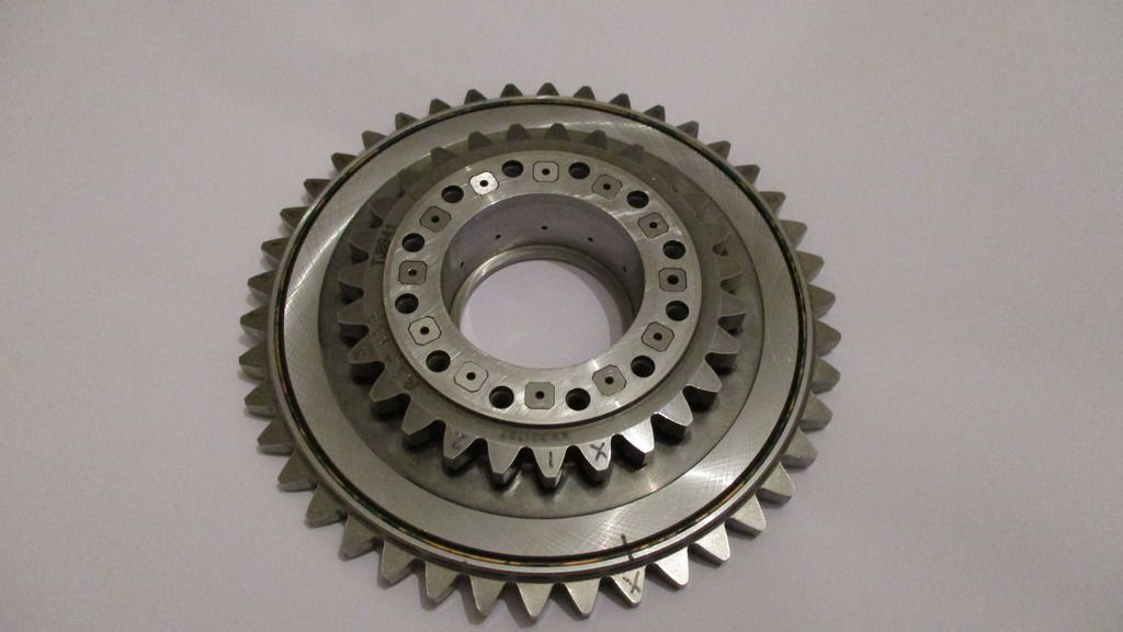
The rear side, hub screws removed for disassembly,
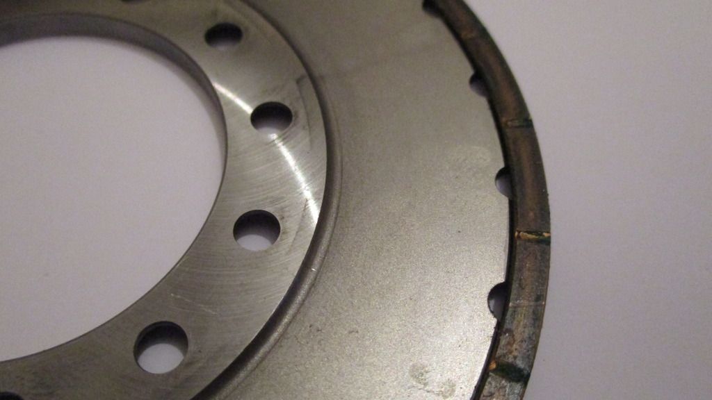
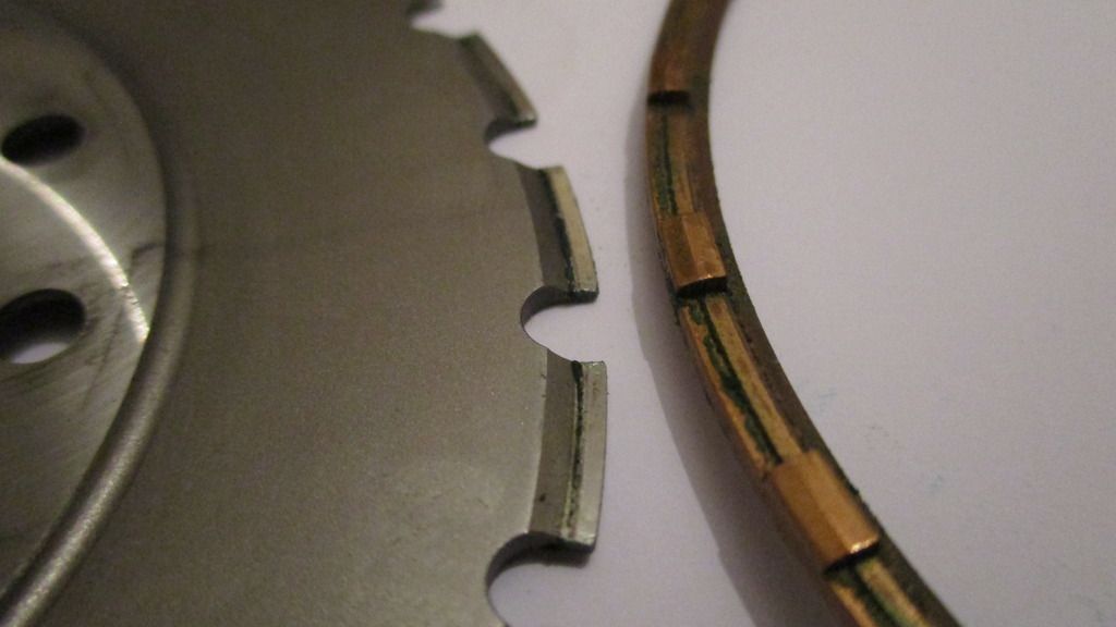
Rear cover removed you can see the detail of the Silicon Bronze axial thrust ring, because there is rotational movement of approx 1.3 degrees between the rear cover plate and the outer ring gear a bearing bronze is used here. It is held from spinning with notched pockets,
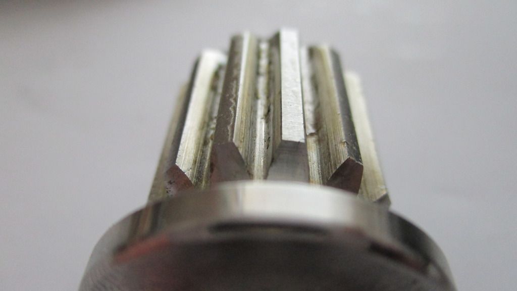
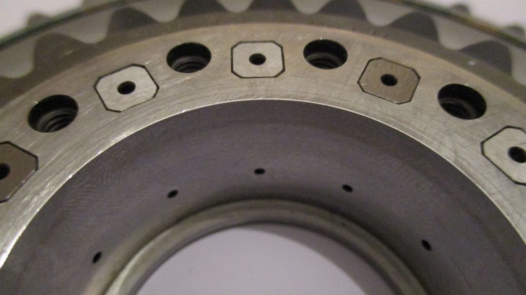
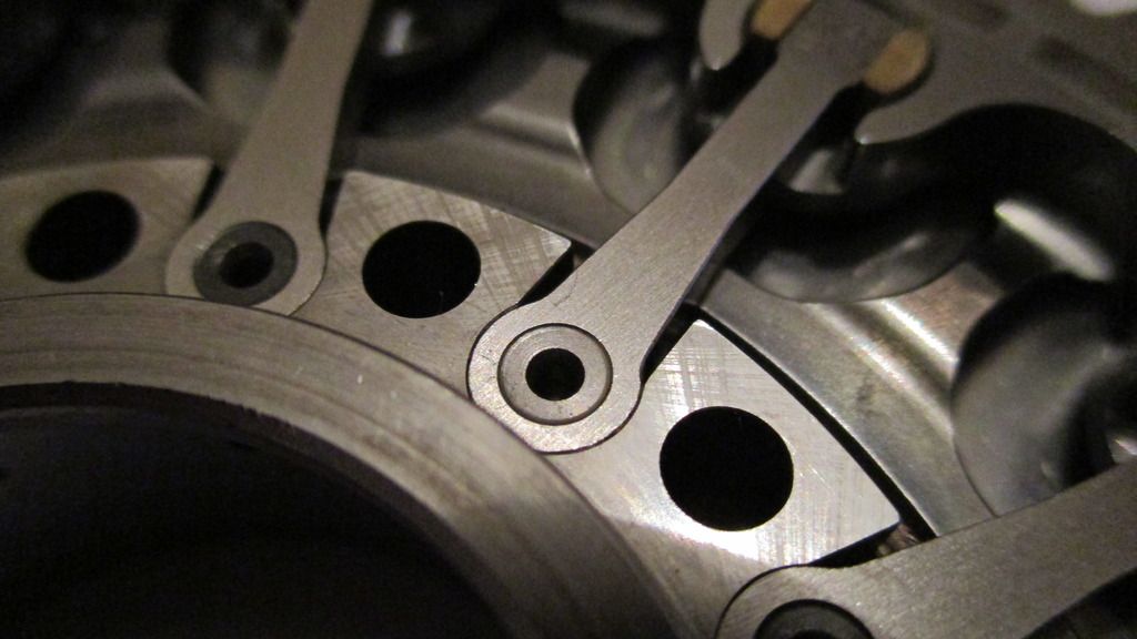
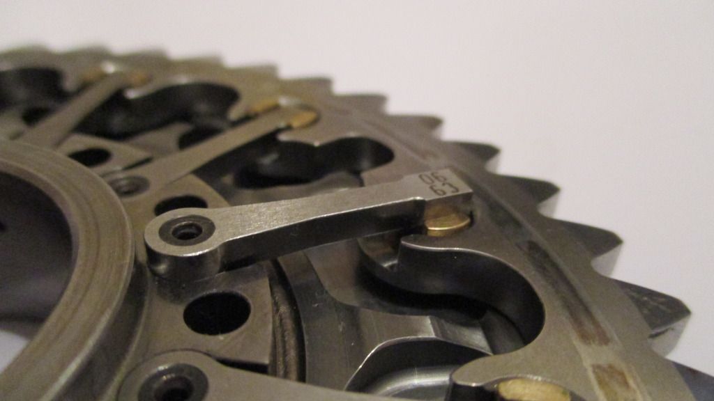
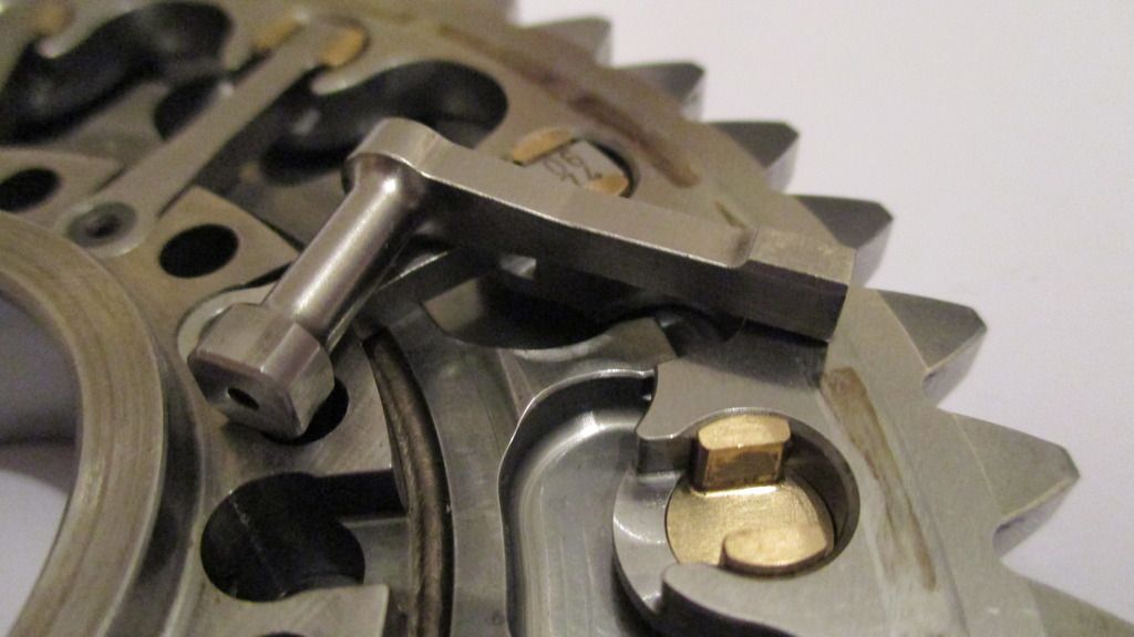
A few close-ups of the inside of the main gear assembly, notice the small torsion bars which are the only parts transferring rotational movement from the center hub, to the outer ring gear,
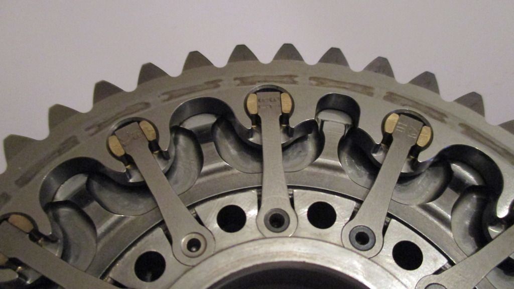
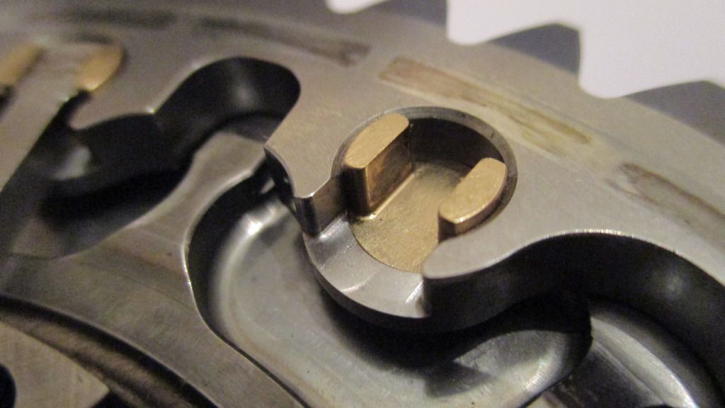
The small torsion bars are machined from one piece of steel and have small arms extending out to bushings in the outer ring gear,
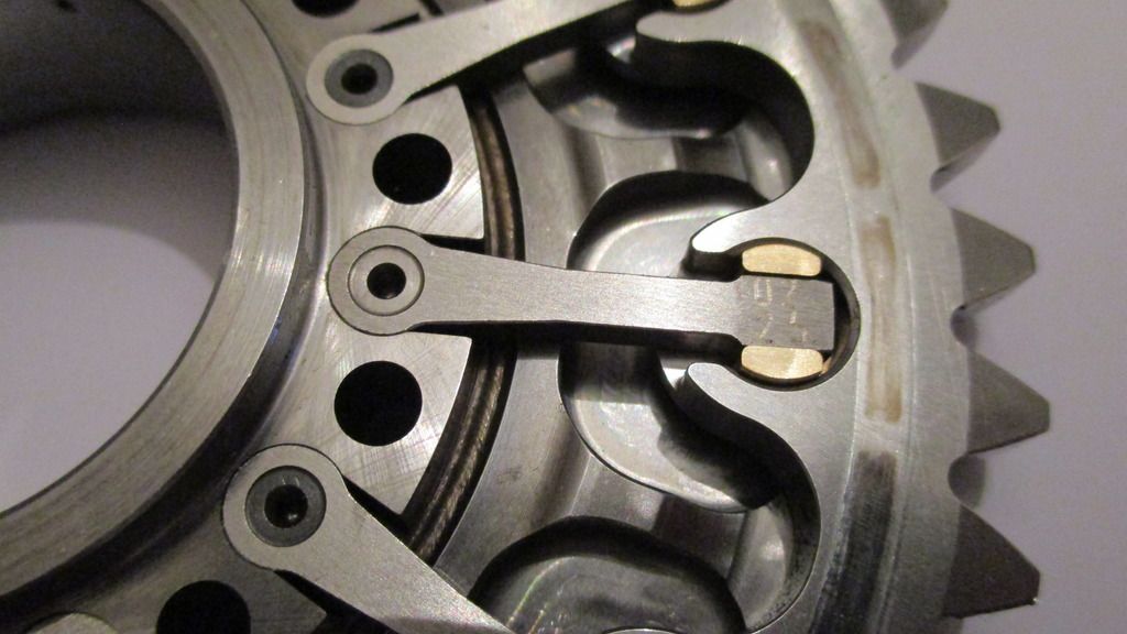
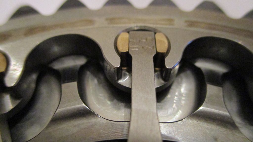
Although the torsion bars look to be two parts, the recess and holes are only there to accurately jig them for the torsion bar section(not shown) grinding operation. Like any torsion bar, the accuracy of the diameter directly relates to its torsional resistance so its extremely important the full set are all the same diameter so as to all act together. If one was slightly oversize then this would be susceptible to more torsional force due to higher resistance than all the others - which would lead to failure,
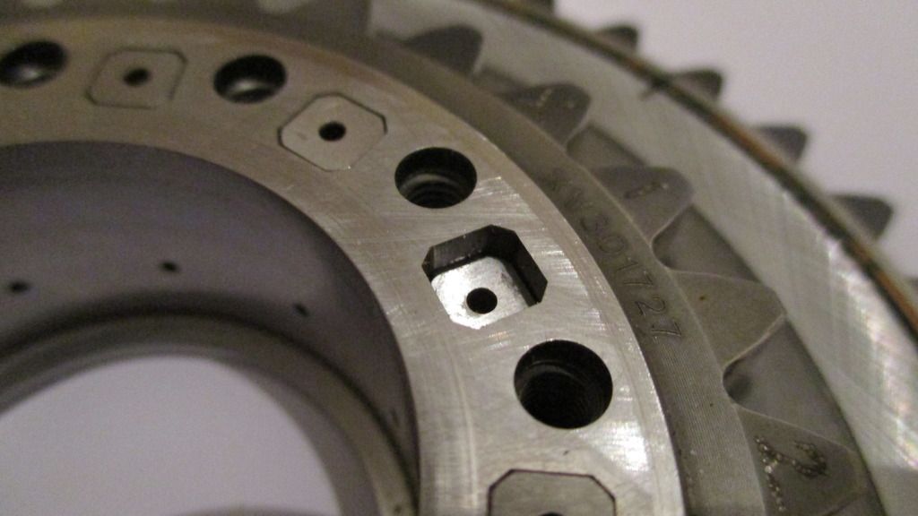
Flipping the F1 Timing Gear Damper over again to drive out one of the torsion bars - these sit in square wire edm'd holes under interference fit so as to stop them rotating,
Flipped over again it starts to emerge,
Out,
The Silicon Bronze location bush also removed, these are required since there is angular motion at the ends of the torsion bars,
Locates clearance fit on the end of bar,
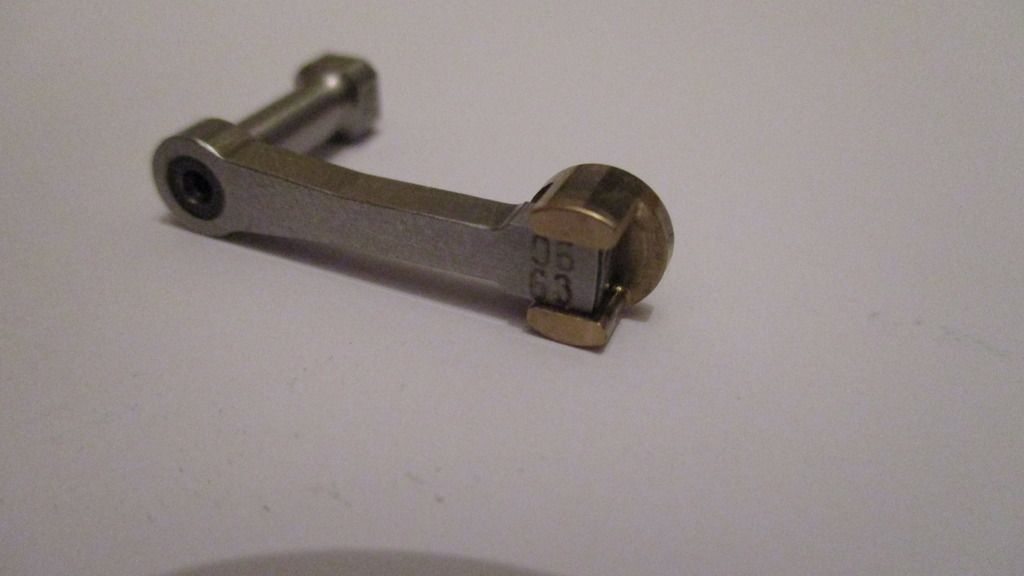
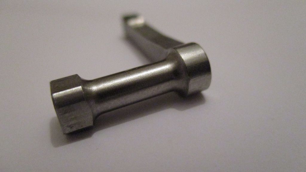
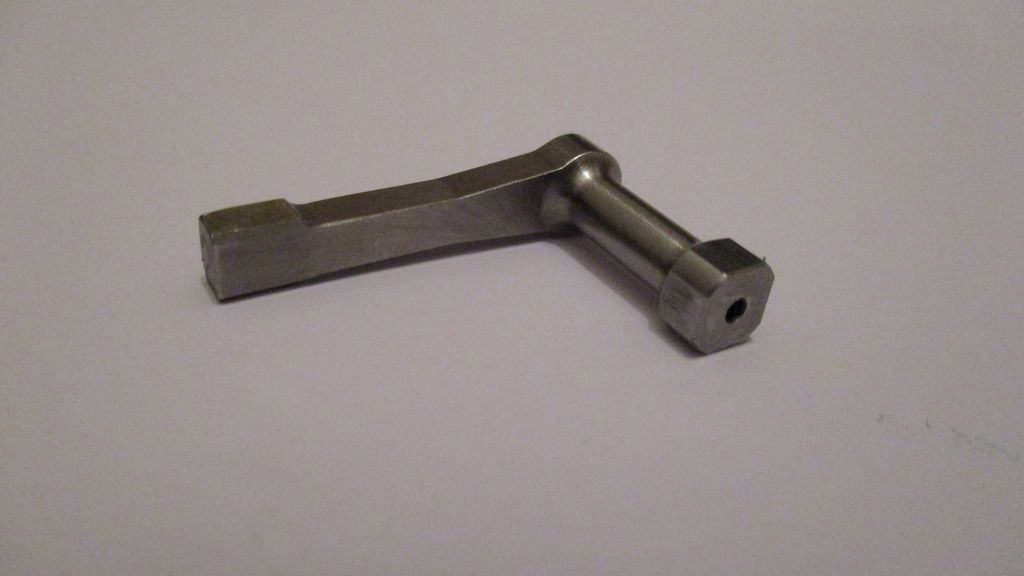
The torsion bar itself - the torsion section now in full view,
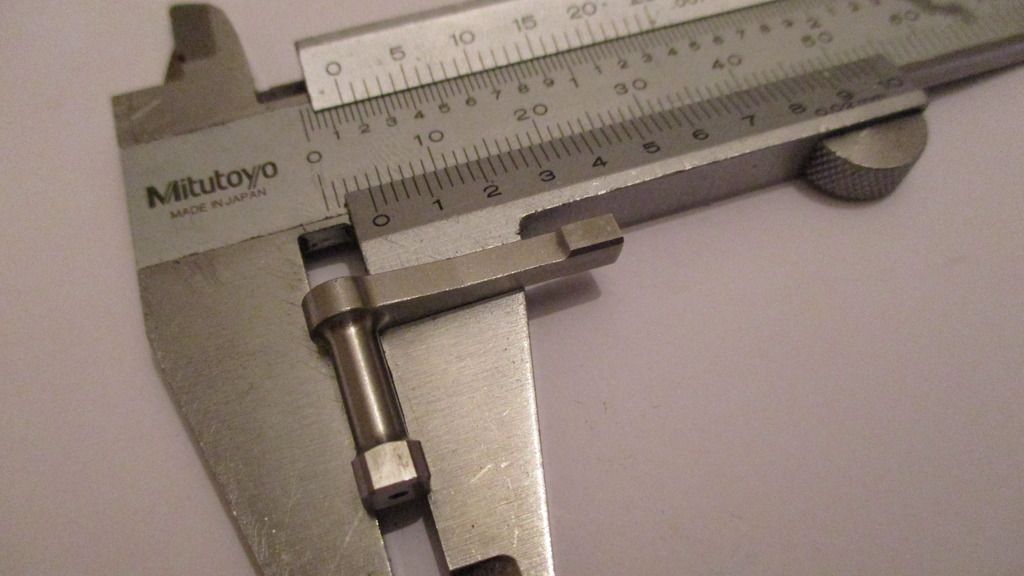
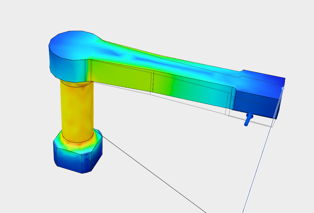
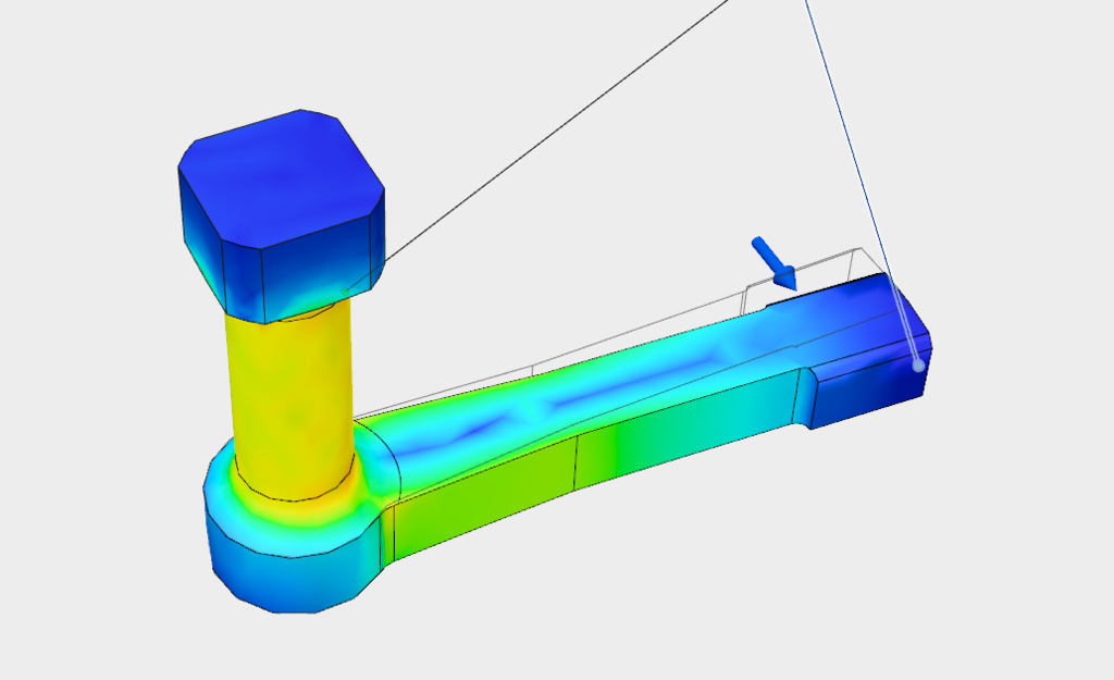
Because it wasn't fully apparent initially as to whether it was the round section, or the arm extending out to the outer ring gear that was the torsion/flexure section I accurately modeled the part in CAD and did a quick stress simulation as it would with the engine running,
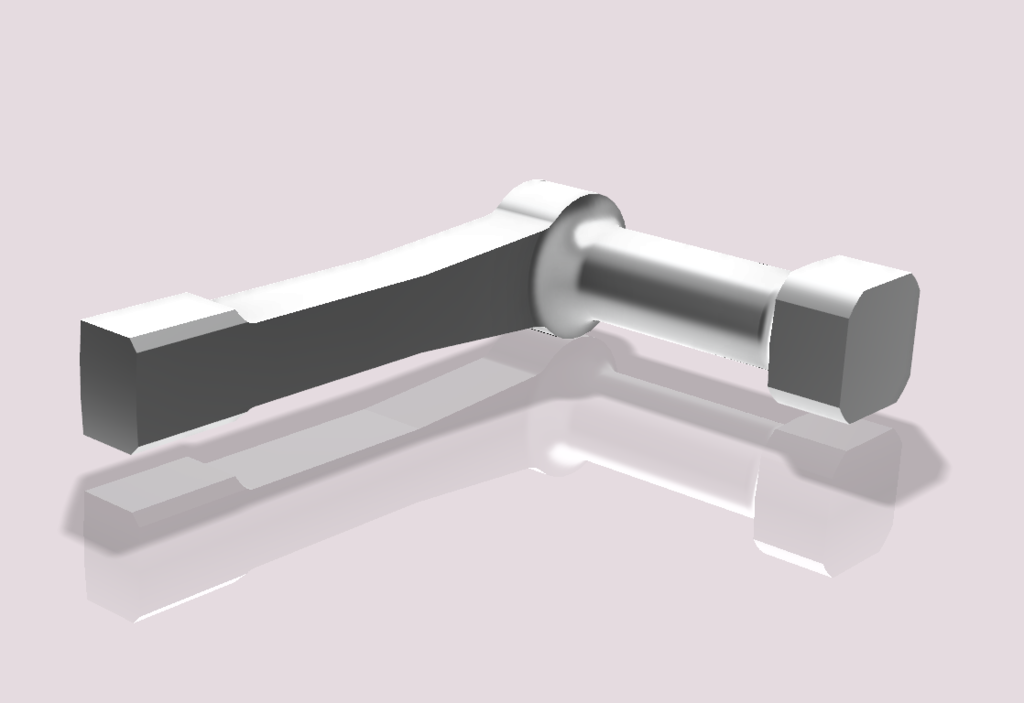
By making the square section fixed, and also inducing overly excessive force around the axis it became apparent that it was indeed the round torsion bar section that was the zone most in torsion, and not the bending of the arm out to the silicon bronze bush in the outer ring gear,
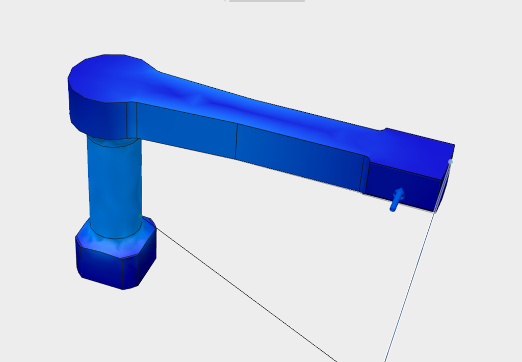
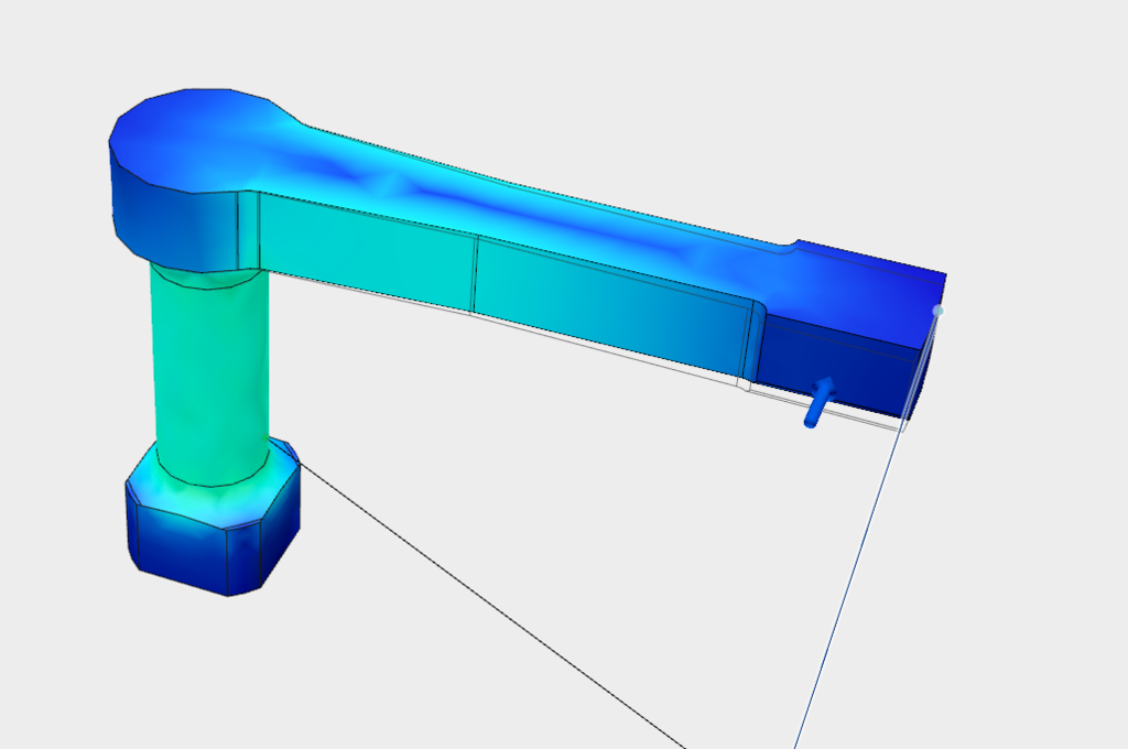
The area in Yellow displaying most strain below at full angular displacement,
So thats pretty much that, interesting part indeed and somewhat like a swiss watch inside when viewed first hand.
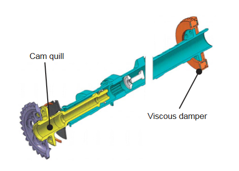
It would be wrong not to mention the same item Keith Duckworth came up with on the DFV back in the 70s...
As you can see below, it contains the same torsion bars - called "Drive Quills", the only difference with the DFV assembly was that it served both heads by using a gear on both sides - crank drive to middle gear hub. This was due to it not being designed in from day one and space being at a premium!
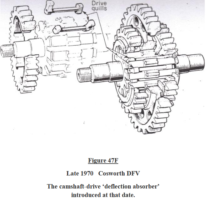
(Image Courtesy of Cosworth Historic - Google Search)
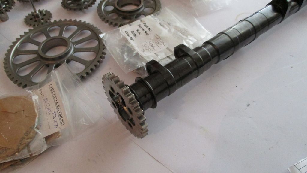
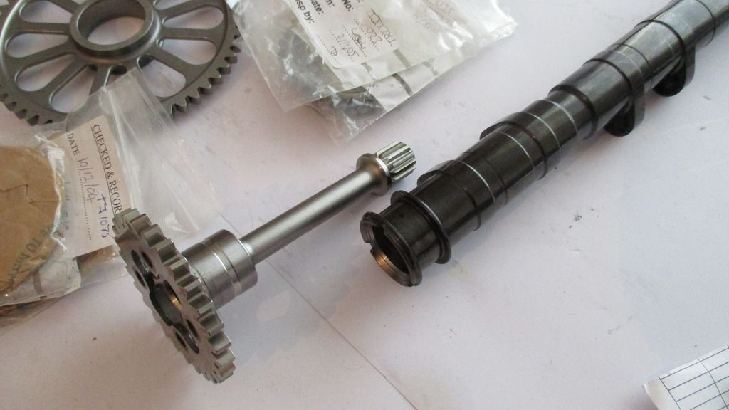
The Gear assembly disassembled below,
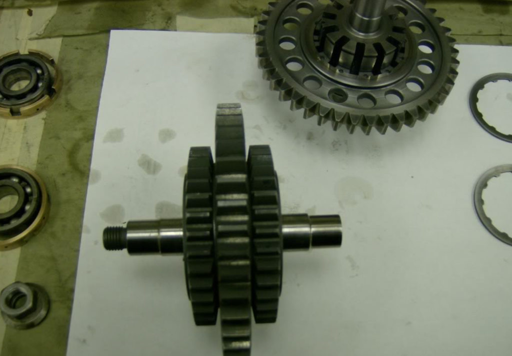
(Image Courtesy of Nick Slade - Google Search)
Drive quills bottom left,
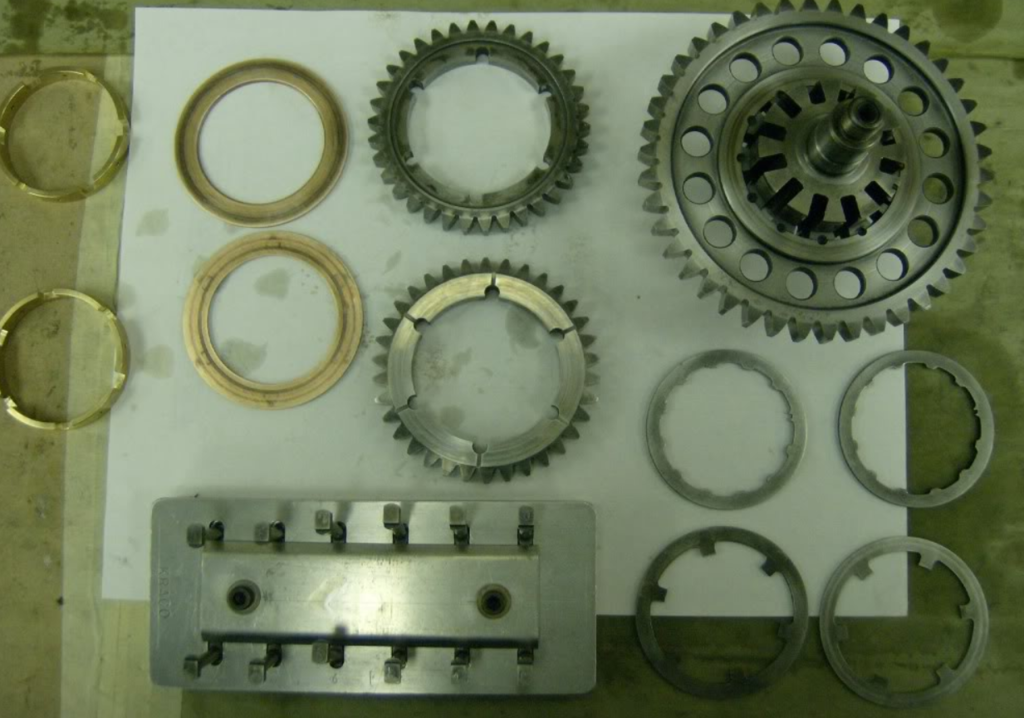
(Image Courtesy of Nick Slade - Google Search)
Because of this I'd like to dedicate this thread in memory of Keith Duckworth - its amazing to see his brain power still in use some 40years later - Once a good idea, always a good idea.
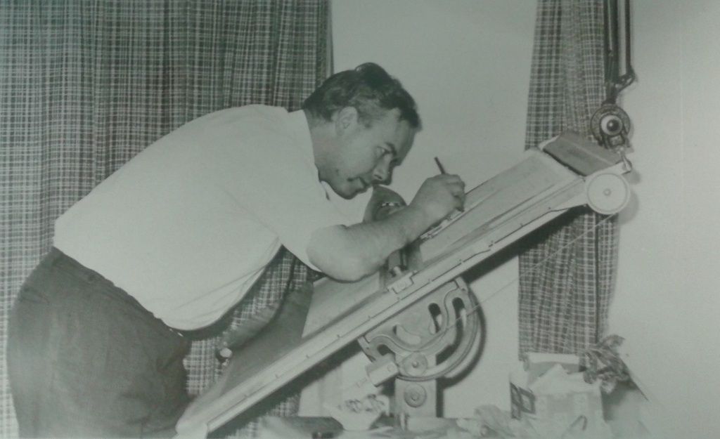
(Image Courtesy of Matt Grant @ Modatek)
With all of the above in mind I hope the thread and information here has helped everyone from Casual Viewers, Enthusiasts, F1 fans, Engineers, Designers, Students, and Teachers Worldwide - If you know anyone whom you think would like to see it please share this link.
All pictures are backed up and on prepay hosting so they are not going to vanish anytime soon - hopefully now there is less doubt as to what it takes to create one of the last and in my opinion the greatest ever modern day 20,000rpm Formula One Engines.
All the Best,
Brian Garvey.