Ferrari F2008 aero-mech development in 2008

Here are our CFD links and discussions about aerodynamics, suspension, driver safety and tyres. Please stick to F1 on this forum.
User avatar
Bob Brown
1
Joined: 24 Mar 2008, 05:20

Re: Ferrari F2008 aero-mech development in 2008

Post

yea I have to say that flute concept would not work well at all. Seems to be too flimsy for one, and if it does get hit, it'll shatter all over the place. Plus I don't really think having that many air intakes would be benefitial to the overall airflow?

Ogami musashi
Ogami musashi
32
Joined: 13 Jun 2007, 22:57

Re: Ferrari F2008 aero-mech development in 2008

Post

Conceptual: your design would be interesting but the problem is that the different holes result in mixing flow which means turbulent flows, so it would be pretty sensible inside the main channel.

If we think about an ideal case, were on the bottom of the nose you have high pressure, inside the main channel low pressure, and above low pressure, your system would provide for boundary layer suction on the bottom of the nose, and provided the pressure on the top of the nose is higher than in the channel (not guaranted) this would enhance downforce....BUT if for a reason (mixing flow, drag..) the pressures changes, like a stall in the main channel, the process is inversed. the main channel stalling will see its boundary layer sucked at the bottom of the nose which will increase the turbulence in this part, and the mixing with the top of the nose will provide lower pressure by boundary layer separation, then you have the inverse sitution with lift produced.


I also think the drag would be very big especially considering the shape and orientation of your "flute holes".

but who knows, maybe the idea is exploitable one day.

Conceptual
Conceptual
0
Joined: 15 Nov 2007, 03:33

Re: Ferrari F2008 aero-mech development in 2008

Post

Ogami musashi wrote:Conceptual: your design would be interesting but the problem is that the different holes result in mixing flow which means turbulent flows, so it would be pretty sensible inside the main channel.

If we think about an ideal case, were on the bottom of the nose you have high pressure, inside the main channel low pressure, and above low pressure, your system would provide for boundary layer suction on the bottom of the nose, and provided the pressure on the top of the nose is higher than in the channel (not guaranted) this would enhance downforce....BUT if for a reason (mixing flow, drag..) the pressures changes, like a stall in the main channel, the process is inversed. the main channel stalling will see its boundary layer sucked at the bottom of the nose which will increase the turbulence in this part, and the mixing with the top of the nose will provide lower pressure by boundary layer separation, then you have the inverse sitution with lift produced.


I also think the drag would be very big especially considering the shape and orientation of your "flute holes".

but who knows, maybe the idea is exploitable one day.
Ogami,

From what you just said, I would say that reducing the flutes to one, taking the air off of the large scoop on the front wing, that at higher speed "stall" it would generate lift.

Will that lift cancel drag or just downforce, because it sounds like it could be good to have it change effect at the stall point if you could tune a specific stall point at a certain speed.

Like a passively adjustable front wing.

Am I off on this?

Chris

User avatar
slimjim8201
12
Joined: 30 Jul 2006, 06:02

Re: Ferrari F2008 aero-mech development in 2008

Post

Conceptual wrote:Pics of my idea. Obviously not exact measurements, just conceptual.


The Fluted nosecone!

http://picasaweb.google.com/CKnopp/Conc ... 4TNfWzBQKA

Chris
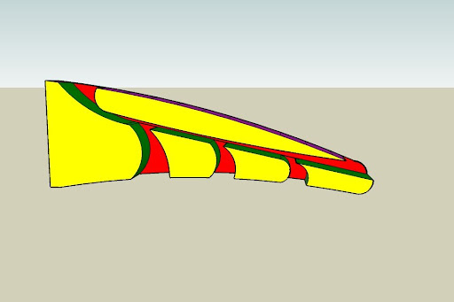
I guess I'm struggling to see what this design will do. From looking at the Ferrari cross section pics, it looks like the nose cone hole allows the air on the underside of the wing to stay attached for the full wing length before traveling up through the nose. Without the nose cone hole as relief, that air would have to divert around the whole nose cone section, and flow separation would occur much earlier on the wing, reducing downforce in that section.

Conceptual, I see your design here as being almost as restrictive as having no holes at all. One of the highest pressure points on the car is at the tip of the nose cone. This pressure will propagate through the nose cone passage until it reaches the exit on top (in your drawing) where the pressure will likely be slightly below atmospheric. I don't think the passage way will "suck" air upwards. Was that the intended design goal?

The big thing here isn't the nose cone or the nose cone shape, or the nose cone hole. It's how all of these factors relate to the real important piece, the front wing.

I nabbed your picture from Picasa...a bit better than just a link:

Image

furnik
furnik
0
Joined: 09 Dec 2005, 11:18

Re: Ferrari F2008 aero-mech development in 2008

Post

ferrari is coping porsche with there gt2 911 if have a look at the front of 911 bonnet there is a vent that is part of there accelerate stability set up the air comes through the centre cooling vent and out of the top vent. im waundering if thats how ferrari is geting around tracktion control ban. if you get a rush of air gets air though underneath and exits the top that would balance the traction a lot its just thought.

User avatar
slimjim8201
12
Joined: 30 Jul 2006, 06:02

Re: Ferrari F2008 aero-mech development in 2008

Post

More to come...

One interesting note. I aligned a cut surface (planar surface to view results on) inside the nose cone hole and I released 40-50 particle traces from this surface, uniformly spaced on the plane. This shows where the air will come from and where it ends up. A very large amount of the incoming air travels through this nose cone hole, and all of that air would otherwise be forced to turn around the nose cone, in the absence of said hole.

Image

Image

Image
Last edited by slimjim8201 on 05 May 2008, 19:34, edited 2 times in total.

Conceptual
Conceptual
0
Joined: 15 Nov 2007, 03:33

Re: Ferrari F2008 aero-mech development in 2008

Post

Anyone else have a problem seeing the pics?

And yes, SlimJim, I think that I will try a new sketch with only a single hole, with some more emphasis on intake shape interaction, as well as the bridgewing mount/vent scoop.

I wish that I had something better than Sketch Up to do these in. Does anyone have a link to a free modeler that exports to the CFD files?

Thanks!

Chris

User avatar
slimjim8201
12
Joined: 30 Jul 2006, 06:02

Re: Ferrari F2008 aero-mech development in 2008

Post

Should work better now. Still trying to figure out the best way to have files hosted. Picasa's not bad...

I'll have the non-hole nose cone simulation completed tonight. This little test is certainly not a full car simulation, but it is an apples to apples comparison. Adding wheels and suspension components would be nice, but frankly, I think these simplified models will tell a pretty big tale. The impact of this nose cone hole is something else...
Last edited by slimjim8201 on 05 May 2008, 19:30, edited 1 time in total.

Conceptual
Conceptual
0
Joined: 15 Nov 2007, 03:33

Re: Ferrari F2008 aero-mech development in 2008

Post

slimjim8201 wrote:Should work better now. Still trying to figure out the best way to have files hosted. Picasa's not bad...
I like it, and the email and included office suite is pretty nice as well!

Chris

alex1015
alex1015
0
Joined: 16 Apr 2008, 05:38

Re: Ferrari F2008 aero-mech development in 2008

Post

slimjim8201 wrote:More to come...
Looks nice, what CFD software are you using and what type (file type) of models does it load? Things from SolidWorks, Pro-E and Inventor I assume?

User avatar
Bob Brown
1
Joined: 24 Mar 2008, 05:20

Re: Ferrari F2008 aero-mech development in 2008

Post

nice pictures, but can I maybe put in a request for one where the air going into the intake is coming from under the front wing? because from that one Ferrari website picture, that was what they were showing so it might be interesting to see how that works

User avatar
slimjim8201
12
Joined: 30 Jul 2006, 06:02

Re: Ferrari F2008 aero-mech development in 2008

Post

alex1015 wrote:
slimjim8201 wrote:More to come...
Looks nice, what CFD software are you using and what type (file type) of models does it load? Things from SolidWorks, Pro-E and Inventor I assume?
CFD software is CFdesign. We have special program for FSAE groups, if you don't have it already. Files from any CAD package are just fine. The big three are SW, Pro and Inv.

User avatar
slimjim8201
12
Joined: 30 Jul 2006, 06:02

Re: Ferrari F2008 aero-mech development in 2008

Post

I threw this together in under 10 minutes so no flaming. I think it looks pretty good actually. Without seeing a really clear shot of the underside of the Ferrari nose cone, I can't really tell where the opening starts. We can see the leading edge of the rear most portion of the opening, but not the front. I've taken a wild guess.

The numbers:

The new, holed nose cone produces approximately 7.3% less drag and 0.9% more downforce than the original, non-holed design.


Image
Figure 1. Normal Nose Cone Traces

Image
Figure 2. New Nose Cone Traces

Image
Figure 3. Normal Nose Cone Traces (Transparent)

Image
Figure 4. New Nose Cone Traces (Transparent)

Image
Figure 5. Normal Nose, Top Side Front Wing Pressure

Image
Figure 6. New Nose, Top Side Front Wing Pressure

Image
Figure 7. Normal Nose, Bottom Side Front Wing Pressure

Image
Figure 8. New Nose, Bottom Side Front Wing Pressure

axle
axle
3
Joined: 22 Jun 2004, 14:45
Location: Norfolk, UK

Re: Ferrari F2008 aero-mech development in 2008

Post

Fantastic work :)

Thanks for sharing.
- Axle

User avatar
slimjim8201
12
Joined: 30 Jul 2006, 06:02

Re: Ferrari F2008 aero-mech development in 2008

Post

The single biggest difference I can see is the high pressure zone in the top center of the secondary front wing with the normal design. The trapped air slows down and the pressure rises. As it turns out, this added pressure doesn't show up in the lift numbers, but it most certainly shows up in the drag numbers. A 0.9% difference in lift is sort of a wash in my mind. These two simulations were produced with nearly identical mesh specifications, with the obvious exception of the design change through the nose.