One issue with hard anodize is that the coated surface has lots of small fractures that will propagate into the underlying aluminum material over time. To inhibit these surface fractures from propagating into the base material, the aluminum surface is normally shot-peened prior to applying a hard anodize coating.
As for PTFE impregnation treatments, it probably doesn't help over the long term. PTFE has extremely limited mechanical strength, and will readily shear off the surface it is applied to if subject to even modest sliding contact pressures.
"Q: How do you make a small fortune in racing?
A: Start with a large one!"
First let me say an immense THANKS to Brian.G for this thread!
I sure hope those in the know still check in here now and again. Even though this thread is now nearly a half a decade old it holds, for me anyway, a massive trove of useful information. I have become involved in a shade tree project to develop a Honda 900RR engine for drag racing purposes. One of the things I have been giving consideration to is pneumatic valve springs. We have basically zero constraints (well aside from available funds) and were considering a max HP/RPM effort, necessitating extravagant/harsh cam profiles that typically provoke very short spring life necessitating very high maintenance requirements as well as possible/likely engine damage due to outright spring brakeage.
So, I am given to understand that these pneumatic spring systems, in F1, typically run at pressures around 10 Bar with valve on the seat and a upper limit of about 20 Bar at max lift. So, gas pressures between 145 psi and 290 psi, now given a lifter area of roughly 1.18 square inches in my case, this would seem to indicate a seat load of 175 lbs. Now given the most aggressive springs I can find for the 900RR application top out at about 50 to 55 lbs. seat pressure, that 175 lbs. number seems pretty high?
So I wonder what the typical valve train weight is in this application and F1 applications in general.
Do they use steel or titanium alloys for valves, titanium buckets with hardened shim over lash inserts?
Further, if, the valve train weight in my application is less (smaller engine/smaller valves/titanium valves/ non-endurance application) would it be appropriate to reduce the seat pressure proportionally, or, is that seat pressure in some sense associated with net valve/cam lift and thereby a decrease in spring pocket volume to produce appropriate specific loading over the nose of the cam. Running some spit ball numbers through the ideal gas law for my case yields a gas pressure at full lift (10mm/0.400”) of about 380 psi and there for a load of about 450 lbs. between the lobe of the cam and the face of the lifter. Again well in excess of the most aggressive racing springs I have access to and yes I am aware that this number can be limited/controlled with a simple poppet valve. Still given the contact patch area for other cam/follower applications I am aware of this is not an excessively high or undoable load as far as the metallurgy goes.
It seems what little information I have been able to chase down (most/all?) F1 pneumatic springs use nitrogen gas as a working medium, I was wondering if anyone out in the real world knows of any disqualifying reasons to the use of CO2 in this application? We already have various mechanisms on the bike that use CO2 for actuations at 125 psi, which seems pretty close to the magic 10 Bar/145 psi number, which would save having a second source and regulator on board.
Finely anyone out there who could point me toward any papers or texts that might give me a primer in the general math and dynamics of these types of systems, I would greatly appreciate it.
Recent F1 engines have almost invariably used finger followers acting directly on a tool steel insert covering the valve stem end.
Intake valves have been titanium or titanium aluminide while exhaust valves have been some form of nickel superalloy or titanium sodium filled. Valve faces have been coated in chromium carbide or chromium nitride.
Bucket tappets are generally unsuitable for very high speed engines due to the poor stiffness and have been avoided.
Each pneumatic valvetrain system has its own set pressure requirement based on peak acceleration and valve mass. You'll have to do the maths for yours - can't really just pinch F1 numbers.
Peak acceleration occurs on the opening and closing ramps rather than at maximum lift - this is very important!
Generally speaking you will have to calculate the valve lift kinematics (valve lift versus cam angle) then derive twice to obtain acceleration. You will find that the valve acceleration is a function of the square of angular velocity - so no, you can't just scale the pressure requirement linearly.
Another important quantity is the first derivative of displacement which gives your valve seating velocity.
Knowing the valve mass and acceleration you can then calculate the pressure requirement and pneumatic bore diameter. The bore diameter will pretty much be limited by how much room you have between valves but generally speaking the larger the bore, the lower the pressure requirement and the longer the seal life.
An important aspect is oil purging. Oil tends to accumulate in the pneumatic body, effectively reducing the volume so pressure relieve valves have to be used.
Unfortunately as far as I am aware there are no off the shelf pneumatic seals and designing them is a very costly exercise. Secondly, you are unlikely to get anywhere without a dedicated cam rig.
Norton's Cam Design and Manufacturing Handbook is what you need to get.
I would also talk to Del West as I bet they have some 'stuff' sitting around that may get you through your first prototype...
I see one or two a month pop up on ebay or some other site, so they are out there. Someone somewhere has a full set for a V10 that they will probably part with.
Do start a thread on your project if you go forward!
I'd suggest F-F, that you do some due diligence/background inquiry,
& search for any existing examples of PV's in drag race usage..
Given the very short max-power runs.. likely perhaps - there is no advantage to be gained..
Certainly, Moto GP engines revving into the high teens use PV's ( 'cept for desmo-Ducati),
but are you really going to be hammering your old Honda mill - that hard, rpm-wise?
If you are, you might find quite a few more things to be concerned about, than valve springs..
"Well, we knocked the bastard off!"
Ed Hilary on being 1st to top Mt Everest,
(& 1st to do a surface traverse across Antarctica,
in good Kiwi style - riding a Massey Ferguson farm
tractor - with a few extemporised mod's to hack the task).
First let me say an immense THANKS to Brian.G for this thread!
Thanks once again for this great thread.
FastFreddy
Just seeing this now - thanks and glad it started some discussion even if it is old now.
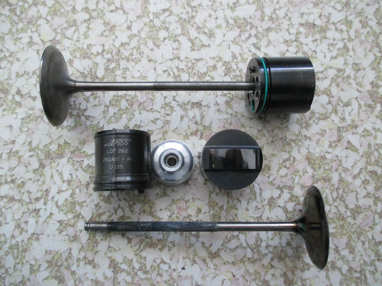
The valve pictured above is indeed the same as I have on hand here. My interest now lies in the newer design, with finger follower and steel sleeve as shown in this more recent thread below,
Ah yes, I do believe I have a copy of Norton’s Cam Design hanging about somewhere or other, I really didn’t remember I had it until you mentioned it. Thanks for that Mudflap.
A system using finger followers in our case seems likely to be well beyond our current technical capabilities, so we are kind of stuck with bucket followers even if they are less than optimal. Then again “hi rpm” is I suppose a relative term, currently we are looking at a best peak HP rpm of about 13250 in the current simulations based on the modified/base 900RR Honda engine, high but not exactly in the rarefied ranges seen in F1 engines.
I have looked at a number of O-ring/seal manufacturers design guides and it seems that there are plenty of off the shelf materials and seal types that are more than capable of dealing with the operational characteristics I envision at this point. Most seal manufacturers seem to agree that about 1500 surface feet per minute is the operational limit for O-rings. At 14000 engine rpm I get around 600 SFM as a maximum number the seals would be exposed to. Pressure, temperatures and oil compatibilities capabilities dependent on material type and are vastly above current expected operating parameters of this engine.
So it seems worth spending some time and money investigating. The basic idea here is to place a set of O-rings in the bores the buckets ride in and replacing the conventional spring retainer with a somewhat similar machined part that would seal the valve stem and also seal to the inside of the bucket thus sealing the assembly. Machine passages in the head casting for inlet and outlet ports with appropriate adjustable one directional valves, slam bam thank you mam got yourself a prototype PV for a Honda 900RR. Add a bit of fixturing and an electric motor to drive the cam in a cast off donor/prototype head and spin it till it flies apart, modify and repeat until reasonably stable.
Thoughts and comment, pro and con, gratefully accepted.
Brian has started to dive into the cam and followers for this same engine in a new thread: viewtopic.php?p=774640&f=4#p774640 He is doing his typically wonderful job of documentation and photography.
The max lift figure (@ the valve) is 16mm: For an engine that revs this hard (19,000 RPM) it's pretty staggering, and makes the need for pneumatic valve-springs blaringly apparent. Thought this detailed cam info would be of particular interest to Fast Freddy as he plots his drag racing domination...
Wanted to make sure everyone caught the new thread as it's really a continuation of what he shared here.
Actually e-jon, AFAIR, the World Championship winning Moto GP Ducati 800cc machine also revved to ~19,000rpm,
of course utilizing their longstanding desmodromic - positive mechanical valve control - set-up.
Ducati still use this system, & of course, when this fails, it goes bang in a big way, as happened recently
(& 'oddly enough', shortly after achieving a circuit top-end speed 'record' - of over 350 Km/h)..
"Well, we knocked the bastard off!"
Ed Hilary on being 1st to top Mt Everest,
(& 1st to do a surface traverse across Antarctica,
in good Kiwi style - riding a Massey Ferguson farm
tractor - with a few extemporised mod's to hack the task).
I have an "F1 Conrod" thread going and I've been going back as far as I can to find examples. I found a 1989 Ferrari V12 rod and went looking for specs on that engine: DESMO valvetrain and a roller-bearing crankshaft! I bet the insane-asylums all over Italy are still full of team mechanics from that year...
To your point, Fast Freddy could buy all of the needed parts at the local Ducati dealership and get on with it. I think the 'stock' parts are good to 15K plus, and with pretty big valves, for the twins anyway.
Sorry to Brian as I've contributed to off-topic-ness.
Norton's Cam Design and Manufacturing Handbook is what you need to get.
As a small 411 for others who might find more camshaft design references texts useful, here is an on line PDF for Cam Design Handbook: Dynamics and Accuracy edited by Harold A. Rothbart published by McGraw-Hill. https://besthope.files.wordpress.com/20 ... k_2004.pdf
Is it possible to use this tech on other engine components besides cylinders like the head or turbo etc?
You mean combustion chamber or ports, or the exhaust manifold? I don't know how you could use it in the combustion chamber itself, wouldn't affect air flow any appreciable way. Or do you mean the valve train? Turbo or MGU-H bearings perhaps?