Using intermediate components to exceed 4MJ per lap energy transfer between ES and MGUK

All that has to do with the power train, gearbox, clutch, fuels and lubricants, etc. Generally the mechanical side of Formula One.
User avatar
henry
324
Joined: 23 Feb 2004, 20:49
Location: England

Re: Using intermediate components to exceed 4MJ per lap energy transfer between ES and MGUK

Post

saviour stivala wrote:
29 Jul 2018, 21:29
Red Rock Mutley wrote:
29 Jul 2018, 12:55
henry wrote:
29 Jul 2018, 11:08
...in particular the note that there are just 2 sensors measuring all the flows in and out of the ES and K.

Do determine if flow from one sensor arrived at the other directly I think there must be some time constraint. Any flows, in direction and magnitude, happening “simultaneously” will be counted towards the flow control restrictions
That's an interesting point. It doesn't seem possible to measure the transfer of energy between the MGU-K and the ES with those 2 sensors. Looking at just the ES, the reg says " One sensor is connected to measure all the electrical energy in/out of the Energy Store". A quick look at the energy flow diagram reveals multiple flow paths of energy in and out of the ES. It doesn't seem possible to seperate the flows using 1 sensor; by definition the flows are combined (summed) before entering and exiting the sensor. More than that, as 2 of the flow paths are marked "unlimited", the total permissible flow in and out of the energy store is similarly "unlimited". So whilst the energy flow can be measured, it doesn't seem possible to separate out the different energy flow paths. And consequently it doesn't seem possible to regulate the 2/4MJ per lap energy transfer limit between the ES and MGU-K

Those sensors are useful in regulating other parts of Appendix 3. Given the ES sensor measures total energy flow in and out, it can regulate the 4MJ limit in difference between the minimum and maximum state of charge of the ES. While the MGU-K sensor can measure the power output of the MGU-K
I am not an electrical engineer but reading the paragraph that ends “consequently it doesn’t seem possible to regulate the 2/4MJ per lap energy transfer limit between the ES and MGU-K” leads me to ask, how is it possible for the governing body the caliber of the FIA to write rules and device the means so as to be able to police their own rules and after 5 years said rules and policing have been in use “it now doesn’t seem possible to regulate the 2/4MJ per lap energy transfer limit between ES and MGU-K?.
They are policing their own rules. However there is an interpretation in the letter of the rules that they didn’t expect.
Fortune favours the prepared; she has no favourites and takes no sides.
Truth is confirmed by inspection and delay; falsehood by haste and uncertainty : Tacitus

User avatar
henry
324
Joined: 23 Feb 2004, 20:49
Location: England

Re: Using intermediate components to exceed 4MJ per lap energy transfer between ES and MGUK

Post

sosic2121 wrote:
29 Jul 2018, 22:08
henry wrote:
29 Jul 2018, 13:27
Red Rock Mutley wrote:
29 Jul 2018, 12:55
So whilst the energy flow can be measured, it doesn't seem possible to separate out the different energy flow paths. And consequently it doesn't seem possible to regulate the 2/4MJ per lap energy transfer limit between the ES and MGU-K

As I said above my supposition is that the counter(s) are synchronised in some way.
This is something I also couldn't get my head around. Basically 2 sensors to messure 3 things.

But Henry proposed elegant idea.
This would mean that MGU-H switching period has to be greater than the sensor resolution.
I suspect the sensor measurement periods are much shorter than the switching periods.
Fortune favours the prepared; she has no favourites and takes no sides.
Truth is confirmed by inspection and delay; falsehood by haste and uncertainty : Tacitus

User avatar
henry
324
Joined: 23 Feb 2004, 20:49
Location: England

Re: Using intermediate components to exceed 4MJ per lap energy transfer between ES and MGUK

Post

Tzk wrote:
29 Jul 2018, 22:27
I assume that sending energy through the H without using it to do any work inside the H (es > h > k) is against the „spirit of the rules“ as it would only happen to try to get around the 2mj/4mj rule.

That said, i assume that the mgu-h may only harvest OR deploy at the same time. This leads to the conclusion that two sensors actually are enough to measure all three devices. Hondas way would work too, as they use the mgu-h as flywheel and switch between harvest+deploy.
The use of the “flywheel” is just to provide a storage mechanism. They might also use the CU storage allowance, 5kJ, or a combination of both.
Fortune favours the prepared; she has no favourites and takes no sides.
Truth is confirmed by inspection and delay; falsehood by haste and uncertainty : Tacitus

User avatar
henry
324
Joined: 23 Feb 2004, 20:49
Location: England

Re: Using intermediate components to exceed 4MJ per lap energy transfer between ES and MGUK

Post

PhillipM wrote:
29 Jul 2018, 14:50
Which may be why the FIA had to put extra software on Ferrari's car to check they were doing it legally at the time.
My understanding was that the FIA was concerned about the SOC and use of two “batteries” in the ES. That, I think, is a different issue to the one we’re discussing.

That’s not to say that Media reporting was accurate, or even that the FIA spokespeople really knew what was happening.

If implemented as I suggest you would need to measure other things to control it and the FIA have no mandate to require the logging or processing of those new measurements.
Fortune favours the prepared; she has no favourites and takes no sides.
Truth is confirmed by inspection and delay; falsehood by haste and uncertainty : Tacitus

Tommy Cookers
617
Joined: 17 Feb 2012, 16:55

Re: Using intermediate components to exceed 4MJ per lap energy transfer between ES and MGUK

Post

henry wrote:
29 Jul 2018, 23:24
The use of the “flywheel” is just to provide a storage mechanism. They might also use the CU storage allowance, 5kJ, or a combination of both.
the CU-H isn't part of the MGU-H
so imo using CU storage (without H flywheeling) doesn't comply with rules permitting energy transfer routed via the MGU-H

User avatar
henry
324
Joined: 23 Feb 2004, 20:49
Location: England

Re: Using intermediate components to exceed 4MJ per lap energy transfer between ES and MGUK

Post

Tommy Cookers wrote:
30 Jul 2018, 00:15
henry wrote:
29 Jul 2018, 23:24
The use of the “flywheel” is just to provide a storage mechanism. They might also use the CU storage allowance, 5kJ, or a combination of both.
the CU-H isn't part of the MGU-H
so imo using CU storage (without H flywheeling) doesn't comply with rules permitting energy transfer routed via the MGU-H
Good point. So the temporary storage has to be at the MGU-H.
Fortune favours the prepared; she has no favourites and takes no sides.
Truth is confirmed by inspection and delay; falsehood by haste and uncertainty : Tacitus

User avatar
Big Tea
99
Joined: 24 Dec 2017, 20:57

Re: Using intermediate components to exceed 4MJ per lap energy transfer between ES and MGUK

Post

Not sure this is the right place to ask, but it is tied in to the thinking and it will sound stupid where ever I ask it, so here goes.
There must be many ways that are not feasible as stand alone but could be used to get unrestricted 'boost'
As mentioned above, Pneumatic energy would be small but stored in an airtank useful for short bursts.
There must be things being looked at, or not, because the returns seem small until added to a restricted amount that other teams do not get.

There is a lot of heat 'floating around' there which is seen a s a problem needing to be disposed of, could it possibly be getting used?

Sterling engine constantly 'topping up' a flywheel? Will not be very efficient in a car,but there is a minimum weight so just as well use it to generate unregulated energy

Thermoelectric generator? I know each is a tiny output individually, but if banks of them are used for shielding it offsets weight.

Hamster in a wheel?
When arguing with a fool, be sure the other person is not doing the same thing.

Dr. Acula
46
Joined: 28 Jul 2018, 13:23

Re: Using intermediate components to exceed 4MJ per lap energy transfer between ES and MGUK

Post

Big Tea wrote:
30 Jul 2018, 11:56
There must be many ways that are not feasible as stand alone but could be used to get unrestricted 'boost'
As mentioned above, Pneumatic energy would be small but stored in an airtank useful for short bursts.
This would breake the rules.
Technical Regulations wrote:5.1.6 Pressure charging may only be effected by the use of a sole single stage compressor linked to a sole single stage exhaust turbine by a shaft assembly parallel to the engine crankshaft and within 25mm of the car centre plane. The shaft must be designed so as to ensure that the shaft assembly, the compressor and the turbine always rotate about a common axis and at the same angular velocity, an electrical motor generator (MGU-H) may be directly coupled to it. The shaft may not be mechanically linked to any other device.

5.14.1 With the exception of incidental leakage through joints or cooling ducts in the inlet system (either into or out of the system), all air entering the engine must enter the bodywork through a maximum of two inlets which are located:
a) Between the front of the cockpit entry template and a point 500mm forward of the rear wheel centre line longitudinally.
b) No less than 200mm above the reference plane vertically.
c) On vertical cross-sections parallel to C-C.
Furthermore, any such inlets must be visible in their entirety when viewed from the front of the car without the driver seated in the car and with the secondary roll structure and associated fairing removed (see Article 15.2.6).
There is a lot of heat 'floating around' there which is seen a s a problem needing to be disposed of, could it possibly be getting used?

Sterling engine constantly 'topping up' a flywheel? Will not be very efficient in a car,but there is a minimum weight so just as well use it to generate unregulated energy
Would also break the rules, because you aren't aloud to connect it mechanicaly in any way to the drive train and for the ERS only the MGU-K and MGU-H are aloud in the car and you can't connect it to the MGU-H either because of Article 5.1.6 already posted above.
5.2.1 The use of any device, other than the engine described in 5.1 above, and one MGU-K, to propel the car, is not permitted.
Thermoelectric generator? I know each is a tiny output individually, but if banks of them are used for shielding it offsets weight.
Same problem, the rules...
Hamster in a wheel?
You monster! Why would you trap a tiny sweet Hamster in the back of a F1 car. What has the Hamster ever done to you to deserve this?

User avatar
Big Tea
99
Joined: 24 Dec 2017, 20:57

Re: Using intermediate components to exceed 4MJ per lap energy transfer between ES and MGUK

Post

Dr. Acula wrote:
30 Jul 2018, 13:46
Big Tea wrote:
30 Jul 2018, 11:56
Would also break the rules,.
[quote[/quote]
Same problem, the rules...
Hamster in a wheel?
You monster! Why would you trap a tiny sweet Hamster in the back of a F1 car. What has the Hamster ever done to you to deserve this?
[/quote]
Is it ruled out? small rodents need employment too

There seem to be 'rules' and RULES though :D
There seems to be a way around them 'if' it is being done
When arguing with a fool, be sure the other person is not doing the same thing.

User avatar
Red Rock Mutley
11
Joined: 28 Jul 2018, 17:04

Re: Using intermediate components to exceed 4MJ per lap energy transfer between ES and MGUK

Post

henry wrote:
29 Jul 2018, 23:17
I’m not sure the energy needs to be stored kinetically. There may be enough energy storage in the CUs to make that unnecessary.
I had to think hard about that one. I get there with the engineering equivalent of a shaggy dog story, but as we know, shaggy dogs win races

There's a question mark of where the sensors are placed. As the CU's are unique, presumably the FIA comes to an arrangement with the engine manufacturer. Further uncertainty surrounds where the single sensor is placed in the permitted dual battery system (because there are 2 battery connections to monitor with 1 sensor)

As a thought exercise, consider this:

We know it is permissible to segment the Energy Store (battery pack). One scheme could be to allocate each MGU a segment of the ES. We know the relative demands on the battery, so the MGU-K would have a large segment (of the battery), while the MGU-H a small segment

The flow paths in and out the MGU-H (to/from ES and MGU-K) are unregulated. In that sense there seems no need to measure the per lap energy transfer in and out of the segment of the ES connected to the MGU-H

During normal (race) conditions the MGU-H transfers energy to the ES only in the final stage of acceleration (when the rain light flashes, and both MGU's are harvesting) otherwise energy is delivered to the MGU-K for extra power

On exiting a corner, when the turbo would otherwise be off-boost, the energy flow is reversed and the MGU-H is driven in motor mode (electric supercharger). This is an intrinsic part of how the hybrid power unit operates

So, the segment of the ES connected to the MGU-H can be said to be a transient (short-term) energy store. It receives and releases energy either side of the braking phase. Consequently, the energy storage of this segment can be made small

[During quali, the MGU-K doesn't harvest at the end of the straight, but MGU-H may switch to charging the ES during the same phase, or the MGU-K could charge both segments of the ES during the braking phase]

[Shaggy dog alert] One possible way around the problem of separating the energy flows for measurement purposes is to use a known value for some of the less dominant paths. For example, the "other ancillaries" path could have a rev-dependant energy consumption figure that can be reasonably estimated by calculation (this can be checked by inspection)

If the small segment of the ES can be shown to have a negligible effect on the total effective capacity of the ES, then it would seem reasonable to use a calculated figure for this path too. As there is no need to measure this path, you would place your 1 ES sensor on the other segment of the ES (the one connected to MGU-K, over which nearly all the energy flows)

During use the energy in and out of the MGU-H is so small and so time limited it would have little effect on the permitted 4MJ effective capacity. However, it would seem reasonable to subtract the calculated effective capacity of the small segment from the total permissible amount and apply that new figure as a new, lower limit, to the large segment [For sake of comprehension, let say the small segment is calculated as 0.1MJ, so we need to apply a measurement limit of 3.9MJ to the large segment]

I believe that now gives the required separation of CU electronics and energy paths (one of which is now unmonitored) to enable your electronic transfer of energy

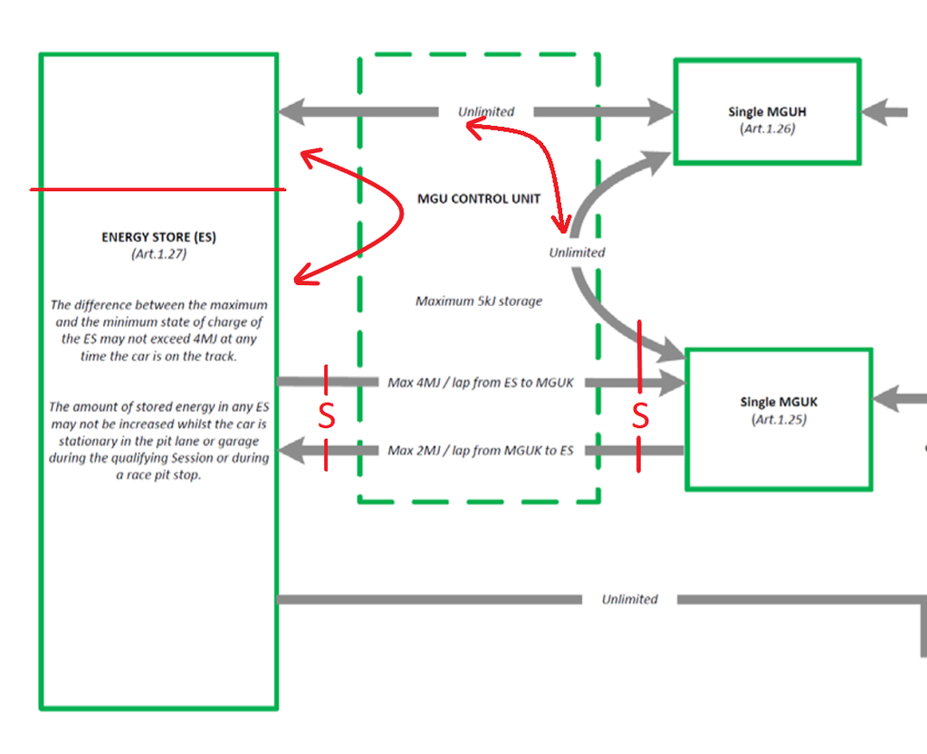
User avatar
Red Rock Mutley
11
Joined: 28 Jul 2018, 17:04

Re: Using intermediate components to exceed 4MJ per lap energy transfer between ES and MGUK

Post

The flow diagram would look something like this

Image

roon
412
Joined: 17 Dec 2016, 19:04

Re: Using intermediate components to exceed 4MJ per lap energy transfer between ES and MGUK

Post

....
Last edited by roon on 30 Jul 2018, 21:25, edited 1 time in total.

Dr. Acula
46
Joined: 28 Jul 2018, 13:23

Re: Using intermediate components to exceed 4MJ per lap energy transfer between ES and MGUK

Post

Red Rock Mutley wrote:
30 Jul 2018, 16:28
The flow diagram would look something like this
Unfortunately you cut an importent section of the flow chart off. In the original one is stated in left lower corner
Control of Energy Managment
  • One sensor is connected to measure all electrical energy into and out of the energy store
  • One sensor is connected to measure all electrical energy into and out of the MGU-K
  • The DC-DC converter may only consume energy. This will be verified by inspection.

User avatar
henry
324
Joined: 23 Feb 2004, 20:49
Location: England

Re: Using intermediate components to exceed 4MJ per lap energy transfer between ES and MGUK

Post

Red Rock Mutley wrote:
30 Jul 2018, 16:28
The flow diagram would look something like this

http://s50.photobucket.com/user/3874619 ... u.png.html
It’s an interesting thought.

It does rather rely on a gentleman’s agreement between Ferrari and the FIA. Ferrari say “we only use this little bit of ES for the MGU-H, because we only use it to deal with turbo lag, like you intended.” And the FIA say “OK”.

In reality at, say, Spa they will run electric supercharger for most of the run through Eau Rouge and up past Rascasse, feeding more than 0.5MJ to the MGU-H and twice that to the MGU-K.

I’m not convinced the FIA don’t know that.
Fortune favours the prepared; she has no favourites and takes no sides.
Truth is confirmed by inspection and delay; falsehood by haste and uncertainty : Tacitus

Tzk
Tzk
33
Joined: 28 Jul 2018, 12:49

Using intermediate components to exceed 4MJ per lap energy transfer between ES and MGUK

Post

As acula pointed out, any bypassing of the current sensor which is placed at the ES would break the rules. You may only run energy through the sensor from or to the ES. There‘s no room for your „agreement“ in the rules.

I belie e that ferrari splits the battery internally into two sections, but still has to run all current through the sensor (energy from/to H and K)