2 stroke thread (with occasional F1 relevance!)

All that has to do with the power train, gearbox, clutch, fuels and lubricants, etc. Generally the mechanical side of Formula One.
manolis
107
Joined: 18 Mar 2014, 10:00

Re: 2 stroke thread (with occasional F1 relevance!)

Post

Hello Pinger

You write:
“but what does the tilting valve bring to the table? Asymmetric timing and if so, in which direction - late?”


In theory the tilting valve enables a different control over the gas flow.

The scavenging starts with a higher pressure just before the transfer ports (outside the cylinder).
At the beginning of the scavenging the fresh gas bursts into the cylinder (which enables an earlier opening of the transfer relative to the opening of the exhaust; the transfer port opens after the exhaust port).
The scavenging starts “positive”: from the opening of the transfer port to the BDC (Bottom Dead Center), the piston (with the tilting valve sealing its back end, and due to the small dead volume in the scavenge pump) displaces the air-fuel mixture into the cylinder positively (it resembles with the exhaust cycle of the 4-stroke engines: no matter what the pressure in the exhaust manifold is, the piston will push positively the burnt gas outside the cylinder).

Things change near the BDC wherein the tilting valve opens.
Now the space inside the piston (i.e. the “crankcase” of the OPRE Tilting) is free to communicate with the cylinder through the open scavenge port, and the scavenging turns from “positive” to “inertial”.
With the inertia of the fast moving gas “column” in the transfer - cylinder - exhaust, the transfer continuous strong till the closing of the transfer port, sucking gas from the space inside the piston and the inlet port.
At the end of the transfer, with the flow of the fresh gas from inside the piston towards the “scavenge pump” (and from the inlet port towards the space inside the piston) already strong, the filling (or overfilling) of the scavenge pump space with fresh gas continues uninterrupted till the closing of the tilting valve near the TDC. After the TDC the already established flow of fresh gas from the inlet port into the “crankcase” continues uninterrupted, while at the same time the gas trapped into the scavenge pump undergoes a compression by the outwards moving piston.

The bigger the tilting valves, the better the breathing at high revs.
The over-square design enables bigger tilting valves to be used (look at the openings between the tilting valve and the back end of the piston):

Image

In the prototype (Opposed Piston) there are two big tilting valves (one per piston), each serving 333/2=166cc of cylinder capacity.
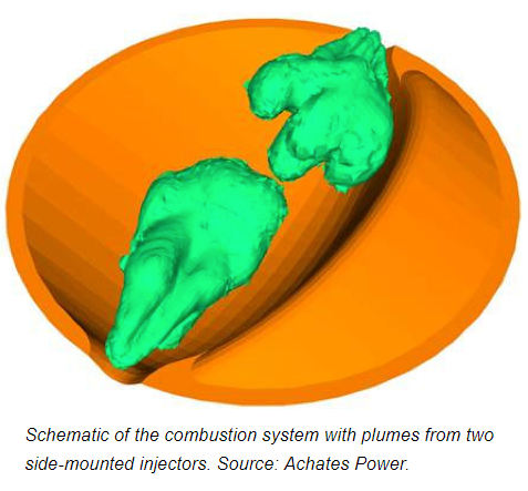
The over-over-square design (84mm bore for 30mm piston stroke in the prototype) besides enabling big tilting valves it is also enabling a “cross” (not loop) scavenging (you can call it cross uniflow) that prevents the mixing of the burnt gas with the fresh gas (say, similar to the through scavenging along the cylinder axis of the Junkers Opposed Piston Air engines).

The pulling-rods is another parameter which relates with the tilting valves: around the BDC the gas and the scavenging feels as working into an engine running at, say, 30% higher revs, which augments anything related with the inertia of the gas.

Regarding the “asymmetry”:
While geometrically the transfer and the exhaust are symmetrical, in practice the transfer appears strongly asymmetrical because it starts true positive (at the expense of some energy for the compression of the gas in the scavenge pump) and continues inertial after the BDC.
The intake is heavily asymmetrical (the inlet port is permanently open, the tilting valve makes the difference).


In practice:

Without reed valves it is saved bulk, weight, cost, noise and problems (what is omitted cannot fail).
The tilting valves (which are nothing but extensions of the connecting rods at their small ends) is reliable, adds no weight, makes easier the lubrication of the wrist pin, etc.

With one only prototype of worse than bad manufacturing quality, the timing used and the dyno test are meaningless. The carburetor used is inappropriate. The spark advance is constant.
With such an attenuated (bad) combustion chamber (worse than Wankel rotary) and the spark plug on the cylinder liner, it should misfire, at least. Yet, the prototype runs without misfiring.
The next cylinder is going to have this combustion chamber:

Image

with spark plugs near its center and strong squeeze; the cross uniflow scavenging is not at all affected by the central narrowing of the cylinder.


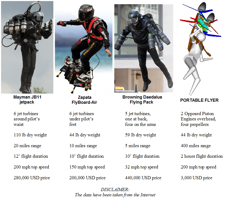
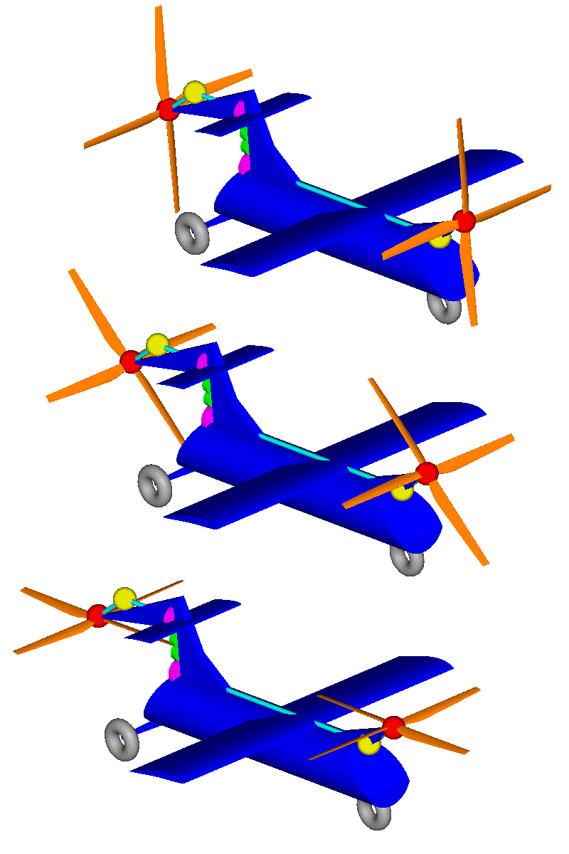
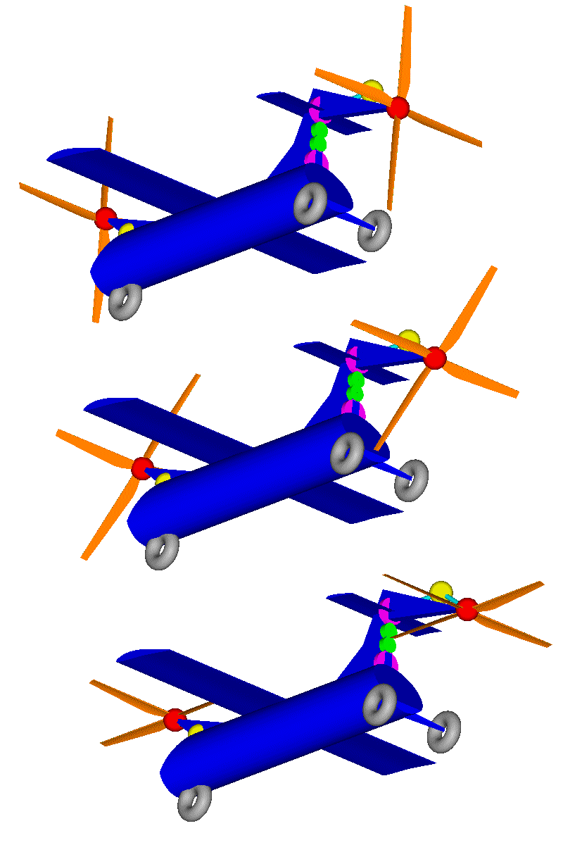
The purpose of the OPRE Tilting engine is to power the Portable Flyer (as it is filed in the GoFly / Boeing competition at http://www.pattakon.com/GoFly/index.html ).
Theoretically, at least, for the high revs it is to work permanently . . .

Thanks
Manolis Pattakos

Pinger
9
Joined: 13 Apr 2017, 17:28

Re: 2 stroke thread (with occasional F1 relevance!)

Post

Thanks for the reply Manolis.
We're not on the same page re our views on scavenging (possibly I am overly conservative) but the answers will emerge during further testing - for which I genuinely wish you good luck.

If 2T is ever to gain (market) traction I think it will be in an OP format. An advantage of yours that you have not mentioned is the close proximity of the crankshafts to each other making a simple two gear connection possible.

I think, unless you can thoroughly cool your proposed addition in the combustion chamber, it will cause you problems both in longevity and a propensity to detonation. Simply providing the pistons with domed crowns (as per early Fiat design) and a very moderate swirl imparted to the incoming charge will achieve your objectives more reliably - IMO.

Don't overlook the necessity of checking for UBHC emission as early as possible (at low loads this can be done with a low cost gas leak tester and suitably sized exhaust reservoir chamber in which the exhaust gases can cool). Unless you intend using direct fuel injection or your proposed end market (flier) is exempt from any emission regulation, then marketing your design may be impossible if it does not adequately restrain UBHC emission.

manolis
107
Joined: 18 Mar 2014, 10:00

Re: 2 stroke thread (with occasional F1 relevance!)

Post

Hello Pinger.

In the Opposed Piston engines the central location of the spark plugs or of the injectors was, and still is, an unsolved issue.

In this drawing of Achates Power Opposed Piston engine they are shown the one piston top and the two fuel sprays injected by two fuel injectors located on the periphery of the cylinder liner:

Image


With its “cross” uniflow, the OPRE Tilting fits with a narrowing at the center of the cylinder, enabling a fat/compact combustion chamber, strong squeeze, and more central location of the spark plugs / injectors.


The “narrowing” is also used in the Opposed Piston PatATi prototype engine (asymmetric transfer and asymmetric intake, loop-scavenged 2-stroke):

Image


More for the PatATi at: http://www.pattakon.com/pattakonPatAT.htm

By thinking of the Opposed Piston PatATi as comprising by two independent halves like the following one:

Image

it becomes obvious the saving over the wall surface and over the thermal loss as compared with a conventional non-opposed-piston 2-stroke (more than half of the cylinder head is missing).


Back to the OPRE Tilting:

The next step will be to eliminate the narrowing and turn the OPRE Tilting into PatBam HCCI, wherein auto-ignition starts at the very center of the cylinder:

Image


Regarding the exhaust emissions:

The three “legal” Jet-Packs have some 100 times lower mileage as compared with the Portable Flyer at right:

Image

If the big issue is the CO2 emissions, they pollute 100 times more.
If the big issue is the UBHC (unburned HydroCarbons), even if all the fuel consumed by the OPRE Tilting exits unburned . . .

Thanks
Manolis Pattakos

Pinger
9
Joined: 13 Apr 2017, 17:28

Re: 2 stroke thread (with occasional F1 relevance!)

Post

manolis wrote:
27 Oct 2018, 05:49
Hello Pinger.

In the Opposed Piston engines the central location of the spark plugs or of the injectors was, and still is, an unsolved issue.

In this drawing of Achates Power Opposed Piston engine they are shown the one piston top and the two fuel sprays injected by two fuel injectors located on the periphery of the cylinder liner:
In the few OP SI engines there have been, domed pistons and duplicated spark plugs are fine. OP CI's have the perennial problem of achieving good scavenging across the entire speed range due to the necessity of extreme swirl. SI is much more tolerant.
manolis wrote:
27 Oct 2018, 05:49

With its “cross” uniflow, the OPRE Tilting fits with a narrowing at the center of the cylinder, enabling a fat/compact combustion chamber, strong squeeze, and more central location of the spark plugs / injectors.
Spark plug bosses require cooling.

manolis wrote:
27 Oct 2018, 05:49
it becomes obvious the saving over the wall surface and over the thermal loss as compared with a conventional non-opposed-piston 2-stroke (more than half of the cylinder head is missing).
An established advantage of OP format.


manolis wrote:
27 Oct 2018, 05:49
Regarding the exhaust emissions:

The three “legal” Jet-Packs have some 100 times lower mileage as compared with the Portable Flyer at right:


If the big issue is the CO2 emissions, they pollute 100 times more.
If the big issue is the UBHC (unburned HydroCarbons), even if all the fuel consumed by the OPRE Tilting exits unburned . . .
CO2 is inevitable and accepted. UBHC is not. Not in road use, hand held tool use, or recreational. Possibly 'aviation' runs to different rules, but is it a market sizeable enough to justify productionising a new engine design when small engined hand held tool sales are in the tens of millions annually?

Tommy Cookers
617
Joined: 17 Feb 2012, 16:55

Re: 2 stroke thread (with occasional F1 relevance!)

Post

afaik all aircraft piston engines run very rich at max power and rich (possibly very rich) otherwise unless leaned manually
so lots of hydrocarbon and carbon monoxide except in cruise

manolis
107
Joined: 18 Mar 2014, 10:00

Re: 2 stroke thread (with occasional F1 relevance!)

Post

Hello all.

Here is a demo PatDan CVJ prototype made of PLA plastic on a 3D-printer:


Thanks
Manolis Pattakos

gruntguru
563
Joined: 21 Feb 2009, 07:43

Re: 2 stroke thread (with occasional F1 relevance!)

Post

manolis wrote:
23 Nov 2018, 10:12
Hello all.

Here is a demo PatDan CVJ prototype made of PLA plastic on a 3D-printer:

Thanks
Manolis Pattakos
Hi Manolis. For a 3D printed part to spin so smoothly is very impressive. Your claim of true constant velocity ratio and high articulation angles is obviously verified. I am also impressed that you didn't edit out the destructive testing at the end. What is the final rotational speed in the video?
je suis charlie

manolis
107
Joined: 18 Mar 2014, 10:00

Re: 2 stroke thread (with occasional F1 relevance!)

Post

Thank you Gruntguru.

In the Youtube video the PatDan CVJ plastic prototype is driven by a blender. The first gear gives 350rpm, the second 500rpm and the final gear (where the mechanism falls apart) gives 700rpm.

It is not exactly the speed that caused the “explosion”.
The 3D-print prototype is the design of the 3D animation:

Image

If you look at the animation carefully (slide-by-slide) at 60 degrees operating angle the “big” ends of the red and blue yokes slightly touch each other. The touching combined with the revs and the poor support of the shafts caused the “problem”.
The prototype is repaired and operational again.

By the way, with 700rpm on the wheels, a typical car goes at about 80Km/h (50mph). The 60 degrees of the CVJ at the driveshaft of each wheel correspond to a U-turn on a narrow road, where the speed of the car is almost zero (and the revs of the driveshaft are way lower than 700rpm).


Worth to mention:

More than 60 degrees operating angle is attainable with proper design of the PatDan CVJ; as for its mechanical efficiency, the way it transfers the motion is quite efficient (think how efficiently the wrist pin between the piston and the connecting rod operates).

In comparison the world's highest maximum operating angle of the Rzeppa CV joints of the automobile drive shafts is only 54 degrees (while the conventional design of the Rzeppa CV joint limits the maximum operating angle to less than 50 degrees).
At wide angles the mechanical efficiency of the Rzeppa CV joint is anything but good. On the other hand, the Rzeppa joints of the front-wheel-drive cars rarely operate at wide angles under heavy load and high revs.


Combining its extreme operating angles with its low-friction and its vibration-free operation, the PatDan CVJ points to some interesting applications, like for instance the following “anti-Osprey” airplane design:

Image

Image

wherein instead of supporting “tilting” engines and transmissions at the ends of the wings of the Osprey V-22:

Image

the engines / transmissions are secured on the fuselage and the only that is tilting is a rotor / propeller at the nose of the airplane and another “pusher” rotor / propeller at the tail of the airplane (counter-rotating at takeoff, and rotating at the same direction at cruising).

Thanks
Manolis Pattakos

manolis
107
Joined: 18 Mar 2014, 10:00

Re: 2 stroke thread (with occasional F1 relevance!)

Post

Hello all

A correction here:

According the drawings,
the two rotors are counter-rotating not only at vertical take-off, at vertical landing and at hovering, but also at cruising.

Having said that,
the “gyroscopic” torque required to change the direction of the disk of the front rotor is permanently equal and opposite to the “gyroscopic” torque required to change (by the same amount and into the same time) the direction of the disk of the rear rotor.

While these two “gyroscopic” torques do load the fuselage of the "Chinook-Osprey-Hybrid", they cancel each other inside the fuselage.

This means that the Chinook-Osprey-Hybrid needs not to lean at some direction to create / provide some “reaction” torque with each weight in order to cancel out the total “gyroscopic” torque, because the total “gyroscopic” torque generated by re-orientation of the two rotors is permanently zero.

Thanks
Manolis Pattakos

J.A.W.
109
Joined: 01 Sep 2014, 05:10
Location: Altair IV.

Re: 2 stroke thread (with occasional F1 relevance!)

Post

Find linked below, a couple of thread relevance/potential topical interest items:

1, Discussion of 'boost bottle' - 2T inlet-tract plenum/resonance chamber tech:

http://www.dragonfly75.com/moto/YEIS.html

2, Honda dyno chart showing outputs of some of their 2T G.P. racing engine designs, from the mid `90s:

https://www.kiwibiker.co.nz/forums/atta ... 1546116747
"Well, we knocked the bastard off!"

Ed Hilary on being 1st to top Mt Everest,
(& 1st to do a surface traverse across Antarctica,
in good Kiwi style - riding a Massey Ferguson farm
tractor - with a few extemporised mod's to hack the task).

noice
1
Joined: 15 Apr 2018, 06:01

Re: 2 stroke thread (with occasional F1 relevance!)

Post

Sorry to quote from way back but there is awful info on 2 stroke slow speed engines.
roon wrote:
16 Jul 2018, 03:56
gruntguru wrote:
16 Jul 2018, 01:56
PlatinumZealot wrote:
15 Jul 2018, 22:00
A cross-head design means blow by . . .
You mean "reduced blow by"?
Blow-by designed in, may be what he means. The piston doesn't need rings nor touch the cylinder wall. The volume beneath the cylinder can be used as a pump as a sort of forced induction. Blow-by would manifest as a sort of EGR, while being oil-free. The piston rod is what gets sealed from the crankcase, and also acts as the piston guide.
This is all incorrect. There used to be PUP (Piston Underside Pumping) in some engines to use the underside of the piston to provide some pressure but I've never seen in use, only description in text.

Blow by will ruin the cylinder, there is 3 compression rings and one oil control ring.

The piston touches the wall, look at the bands on the piston skirt below the rings, they are made of bronze and allow the rings not to get overloaded by friction.

Image

Piston rod is sealed by the stuffing box, it is a series of brass and cast iron scraper rings that are spring loaded against the piston rod. They cannot support any weight. The crosshead and bands on the piston skirt locate the piston.

Image
PlatinumZealot wrote:
19 Jul 2018, 01:03
The speed is just above 103 rpm to 125 rpm at full load for the slow speed engines ( power generation - I am not familiar with their use on ships, but ships require variable operating loads and speeds). You can hear each explosion when you stand beside the cylinders.
Smaller two stroke engines run at 90-130 rpm, stuff in the 10,000-20,000HP range. Larger engines will be 90-100rpm area, long stroke engines may be lower than that.

The bigger the ship, normally the propeller becomes larger, tip speed starts to cause cavitation that damages the blade so the speed of the shaft is lowered.

130 rpm is the highest I have seen on 600ft tankers with a 16-18KHP engine.

94 rpm is the lowest I have seen on 1000ft containership with a 77KHP engine.

There is of course ships above and below this, but of the 20 or so ships I have been an engineer on, that is the trend I have seen.

Tommy Cookers
617
Joined: 17 Feb 2012, 16:55

Re: 2 stroke thread (with occasional F1 relevance!)

Post

recently a stroked version of a slow-speed marine engine was announced as able to run continuously at 7 rpm for 10% power
in 1911 the first Diesel loco had direct drive (2 stroke V4 engine run at high load as a compressed air engine up to 7 mph)
it worked tolerably well - well enough to break its transmission
others were similar in design philosophy (eg even using steam for starting at full load)

hybrid F1 is fuelled notionally for constant torque up to 10500 rpm
and has technology to control fuelling/combustion to '0 rpm' rate - as true Diesels were doing over a century ago
with eg its electrically driven supercharging F1 could have its maximum torque notionally at 0 rpm
as did such differentially boosted CI engines as were made and successfully tested 50 years ago

surely it's now possible to make a piston ICE that will directly drive an F1 car (or a road car) ?
the technology exists (controlling combustion rate and charge) for the ICE to pull maximally (ie hill starts) from 0 rpm
(ok it might always be better to involve the electric motor with the ICE in road vehicles)

PhillipM
385
Joined: 16 May 2011, 15:18
Location: Over the road from Boothy...

Re: 2 stroke thread (with occasional F1 relevance!)

Post

manolis wrote:
25 Nov 2018, 09:23
More than 60 degrees operating angle is attainable with proper design of the PatDan CVJ; as for its mechanical efficiency, the way it transfers the motion is quite efficient (think how efficiently the wrist pin between the piston and the connecting rod operates).
- Because it's floating on a constant oil wedge - I think you'd be struggling massively to pressure feed oil to journal bearings in that.
Your alternative is large ball bearings on every joint and the whole thing encased in grease or oil bath, which would lead to some formidable power losses at anything approaching high speeds with all those linkages running in it.
manolis wrote:
25 Nov 2018, 09:23
In comparison the world's highest maximum operating angle of the Rzeppa CV joints of the automobile drive shafts is only 54 degrees (while the conventional design of the Rzeppa CV joint limits the maximum operating angle to less than 50 degrees).
At wide angles the mechanical efficiency of the Rzeppa CV joint is anything but good. On the other hand, the Rzeppa joints of the front-wheel-drive cars rarely operate at wide angles under heavy load and high revs.
Heavy load is exactly where they take the highest angles - when the car is at low speeds in a low gear with the most wheel torque being delivered. A Rzeppa is also going to be far more compact for the same torque capacity compared to that design, and CV joint size is a huge design issue in vehicles.

You also have no facility for driveshaft plunge in that design, without using external sliding spines or similar, which are awful in terms of NVH due to the high friction levels. Or a ball-spline shaft which is even more bulk and weight.

gruntguru
563
Joined: 21 Feb 2009, 07:43

Re: 2 stroke thread (with occasional F1 relevance!)

Post

PhillipM wrote:
04 Feb 2019, 00:11
manolis wrote:
25 Nov 2018, 09:23
More than 60 degrees operating angle is attainable with proper design of the PatDan CVJ; as for its mechanical efficiency, the way it transfers the motion is quite efficient (think how efficiently the wrist pin between the piston and the connecting rod operates).
- Because it's floating on a constant oil wedge - I think you'd be struggling massively to pressure feed oil to journal bearings in that.
Your alternative is large ball bearings on every joint and the whole thing encased in grease or oil bath, which would lead to some formidable power losses at anything approaching high speeds with all those linkages running in it.
manolis wrote:
25 Nov 2018, 09:23
In comparison the world's highest maximum operating angle of the Rzeppa CV joints of the automobile drive shafts is only 54 degrees (while the conventional design of the Rzeppa CV joint limits the maximum operating angle to less than 50 degrees).
At wide angles the mechanical efficiency of the Rzeppa CV joint is anything but good. On the other hand, the Rzeppa joints of the front-wheel-drive cars rarely operate at wide angles under heavy load and high revs.
Heavy load is exactly where they take the highest angles - when the car is at low speeds in a low gear with the most wheel torque being delivered. A Rzeppa is also going to be far more compact for the same torque capacity compared to that design, and CV joint size is a huge design issue in vehicles.

You also have no facility for driveshaft plunge in that design, without using external sliding spines or similar, which are awful in terms of NVH due to the high friction levels. Or a ball-spline shaft which is even more bulk and weight.
"Large ball bearings" would be unusual in an application like this eg needle rollers are well proven in Hookes joint usage.

The high angle joint in most cars (the outer joint) doesn't usually accommodate plunge. That is normally done at the inner joint which could remain a Rzeppa, tripod etc.
je suis charlie

PhillipM
385
Joined: 16 May 2011, 15:18
Location: Over the road from Boothy...

Re: 2 stroke thread (with occasional F1 relevance!)

Post

But if you run Hookes at large misalignment angles you get pretty severe fretting on the needles usually.

A lot of the really high angle joints aren't normal passenger cars but long-travel offroad or 4x4 vehicles, many of which still require plunge at the outer joint simply because the inner joint can't cope with enough, not so much on more modern suspension systems but they are also the ones where the size of this would rule it out straight away.

Post Reply