Cosworth TJ V10 Piston

All that has to do with the power train, gearbox, clutch, fuels and lubricants, etc. Generally the mechanical side of Formula One.
63l8qrrfy6
368
Joined: 17 Feb 2016, 21:36

Cosworth TJ V10 Piston

Post

Earlier this year I've acquired an used TJ piston as well as a rod courtesy of BrianG.
I thought it would be an interesting exercise to attempt to calculate the piston thermal and mechanical loads based on the information available on these engines.

The TJ was Cosworth's last F1 V10 having been introduced in 2003 and replaced in 2006 by the CA V8. Towards the end of its development it reached 19,000 RPM and a peak power of about 920 hp. Engine life was 800-900 km.

The piston is of a fairly standard box bridged construction and made of A2618 which has been used in Cosworth pistons since the DFV. The billet is forged, then machined. The undercrown is shot peened and polished while the crown is simply just polished. The skirts are Xyalan (1000s series) coated. DLC coatings were experimented with but the processes for applying DLC to aluminium were still in their infancy at the time and usually resulted in poor substrate adhesion or reduction in strength due to the high temperatures required.

The exhaust valve pockets break out into the top land, while the intake pockets are fully contained within the crown and form a thin wall at the closest point to the top land. As the TJ did not have compound valve angles the crown dome is fairly clean.

Image

An interesting feature is the small pocket on the under crown that matches the intake squish land.
The pin bore ribs are slightly angled, presumably to direct the load towards the T rib. This sometimes has the disadvantage of reducing the ring belt support, particularly for larger bore pistons. By contrast, the 98 mm diameter CA piston had straight pin bore ribs aligned with the T ribs.
The ribs blend nicely into the crown with approx. 4 mm rad fillets.

Image
Image

The top ring land is relatively high. There are no gas slots - the gasses energizing the top ring have to travel through the clearance between the ring and the groove. Below the top ring there is a standard vee shaped accumulator groove. The oil control ring groove contains 8 oil drain holes.

Image

The piston skirt has an ample relief at the bottom - this is evident in the wear pattern since the xylan coating is almost untouched.

Image

The rod thrust faces have shallow angled grooves machined to provide lubrication. These grooves break out into small axial relieves in the pin bore.
The piston pin runs straight into the aluminium bore.
Each pin bore half has edge relieves at both sides. Again this is evident from the dark contact marks which are offset away from the edges.

Image

To be able to analyze the piston I created a rough but hopefully representative CAD model.
There is a slim chance I might be able to CMM it at work next year but for now it will have to do.

Image

Some general dimensions in mm:

Image
Image

Next on the list was to create an engine cycle simulation model to estimate the cylinder pressure, gas temperature and crown heat transfer coefficient. This was achieved by building a single cylinder model in a free version of Lotus Engine Simulation available online.

The objective was to tweak the model in order to achieve a peak cylinder pressure of around 100 bar as this was the maximum suggested by Honda at peak torque during the V8/V10 eras. The simulation used an unmodified Vibe curve for heat release and Annand's correlations for HTC prediction.

Image
Image

The cycle average temperature and HTC were used to define the boundary conditions in a thermal FEA.
For cooling, the piston spray velocity was calculated by solving Bernoulli across the nozzle (assuming 0 velocity within the oil gallery) for 8.5 bar oil pressure. The nozzle velocity obtained was 45.8 m/s. This might seem high but Cosworth have stated that the CA piston (42.4 m/s peak velocity) could outrun the spray at peak engine speed since the engine was running 1 bar lower oil pressure.

The calculated spray velocity was used to compute Re for use with a jet HTC correlation (Jigi and Dagn in this case). For piston surfaces not directly sprayed the flat plate correlation was used taking mean piston speed for Re calculation.

As such the thermal boundary conditions are:

Image

These were used in an Ansys FE model to predict temperature distribution. Since I ran most of the simulations at home on the work laptop I had to keep the size of the models very small. As such I was forced to use a piston quarter model, even though the piston is not exactly symmetric about the pin axis.

Temperature distribution in °C is predicted to be:

Image
Image

The cylinder pressure trace was used to calculate piston loads at 19000 RPM over an engine cycle. The maximum vertical, minimum vertical and maximum lateral (thrust) loads were extracted from the loading history and used for FEA and fatigue analysis.

The piston load history is shown below:

Image
Image

At peak cylinder pressure a part of the load is relieved by the piston inertia acting in the opposite direction. This is commonly referred to as inertia relief. At this particular point, reducing either the piston mass or the engine speed would results in an increase in piston load. It is again known that when FIA imposed engine speed restrictions during the V8 era some manufacturers (Cosworth included) had to redesign their piston for this particular reason.

Notice that the 100 bar cylinder pressure given by Honda was given at peak torque, while I have used it at peak power. For a proper piston analysis all relevant engine speeds with the correct pressure trace should be represented.
As a consequence, the piston loading for these calculations will be over-estimated. This will be obvious when looking at the fatigue results later.

As a reference for how much the cylinder pressure can be expected to decrease between peak torque and peak power engine speeds I've estimated that the CA piston only saw 70 bar pressure based on piston loads published by Cosworth in RET.

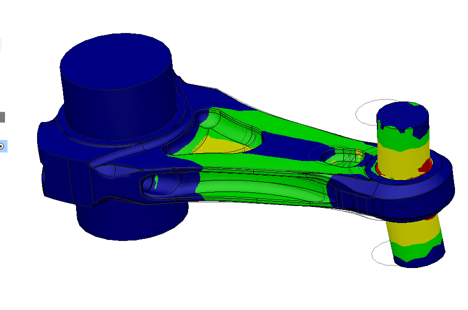
Some FE results of pin bore contact pressure are shown below.

Contact pressure distribution during peak cylinder pressure at 19000RPM (just after TDC, power stroke):
Image

Contact pressure distribution during maximum vertical load at 19000RPM (TDC, exhaust stroke):
Image

Maximum tensile stress:
Image

Maximum compressive stress:
Image

Maximum compressive stress at peak piston thrust:
Image

The stress history was brought into nCode DesignLife for fatigue calculations.
Assuming that the engine operates at an average speed of 15000 rpm for 900 km the required life of the piston is 1e7 cycles. In the plot below black denotes failure at fewer than 1e7 cycles.

Image

In reality the engine would operate at full load/ full speed for maybe half of its life. The fatigue prediction is overly conservative since I do not know the actual duty cycle and I have over-estimated the firing loads. It is interesting that all traditional piston failure areas are highlighted: the pin bore, the bore strap, valve pockets and the blends between ribs and crown.

I have left out a a fair bit of data in order to make this more accessible but I am open to go into more detail if requested.

Time permitting I will have a stab at doing something similar with the rod from Brian.
Last edited by 63l8qrrfy6 on 01 Jan 2019, 19:55, edited 3 times in total.

User avatar
henry
324
Joined: 23 Feb 2004, 20:49
Location: England

Re: Cosworth TJ V10 Piston

Post

Thanks for that. I find it fascinating to see the relationships between the various tools you have used. I’ll need to return to this a few times.

Late entrant but I’d say post of the year.
Fortune favours the prepared; she has no favourites and takes no sides.
Truth is confirmed by inspection and delay; falsehood by haste and uncertainty : Tacitus

trinidefender
317
Joined: 19 Apr 2013, 20:37

Re: Cosworth TJ V10 Piston

Post

You may have seen this but it still has some nice information that may be able to help. It alludes to maximum power at close to 18,000 rpm.

http://www.heron.co.at/_lccms_/download ... nglish.pdf

Just note that this is for the Mercedes FO110 although I would imagine that the information is relatively applicable.

Brian.G
334
Joined: 10 Dec 2010, 23:52
Location: Ireland
Contact:

Re: Cosworth TJ V10 Piston

Post

Mudflap - top thread!

To save you trouble maybe - I must tell you I now have the entire TJ engine in CAD. I also used CMM and various other methods.

While I don't want to share the full CAD assembly, I can send you the Conrod file if you were willing to send me the piston file - its the one part I had left and didn't get a chance to CMM this year.

Its important to note also my full CAD assemble is going towards a mega thread on here shortly so the piston file would be brilliant if you are willing.

Image

Once again, great work above!

Brian,
Last edited by Brian.G on 23 Dec 2018, 17:22, edited 1 time in total.
If you think you cant, you wont, If you think you can, you will

bill shoe
151
Joined: 19 Nov 2008, 08:18
Location: Dallas, Texas, USA

Re: Cosworth TJ V10 Piston

Post

Wonderful to see GPT members apply their expertise to F1 parts.

63l8qrrfy6
368
Joined: 17 Feb 2016, 21:36

Re: Cosworth TJ V10 Piston

Post

Thanks trinidefender, I did not know about that paper - it would have helped massively.

Brian, I am happy to share the CAD files with everyone - what's a good convenient file sharing service nowadays ?

User avatar
dren
226
Joined: 03 Mar 2010, 14:14

Re: Cosworth TJ V10 Piston

Post

Excellent read Mudflap, thanks for the parts sharing BrianG!
Honda!

User avatar
djos
113
Joined: 19 May 2006, 06:09
Location: Melbourne, Australia
Contact:

Re: Cosworth TJ V10 Piston

Post

Amazing work Mudflap, thankyou. =D>
"In downforce we trust"

User avatar
JohnP
1
Joined: 03 May 2018, 15:34

Re: Cosworth TJ V10 Piston

Post

Mudflap - I wanna pick up what you wrote about the CA engine.
The piston pin runs straight into the aluminium bore. Copper bushes were only introduced for the CA.
Each pin bore half has edge relieves at both sides. Again this is evident from the dark contact marks which are offset away from the edges.
The CA piston pin runs also in a aluminum bore. The attached picture of my CA(2010-2013) piston shows a aluminum bore. https://www.dropbox.com/s/bby3j1sz5ncvc ... n.jpg?dl=0

I appreciate your amazing thread with certainly much efforts. =D>

63l8qrrfy6
368
Joined: 17 Feb 2016, 21:36

Re: Cosworth TJ V10 Piston

Post

JohnP wrote:
28 Dec 2018, 23:54
Mudflap - I wanna pick up what you wrote about the CA engine.
The piston pin runs straight into the aluminium bore. Copper bushes were only introduced for the CA.
Each pin bore half has edge relieves at both sides. Again this is evident from the dark contact marks which are offset away from the edges.
The CA piston pin runs also in a aluminum bore. The attached picture of my CA(2010-2013) piston shows a aluminum bore. https://www.dropbox.com/s/bby3j1sz5ncvc ... n.jpg?dl=0

I appreciate your amazing thread with certainly much efforts. =D>
My mistake - you are correct. I have removed that comment from the post.
Thanks again.

User avatar
PlatinumZealot
550
Joined: 12 Jun 2008, 03:45

Re: Cosworth TJ V10 Piston

Post

Great work mudflap =D>

Good technique of connecting different models and calculations. That is something to be respected and applauded.

Question time..

How did you connect the oil jet velocity to the cooling? You assumed complete coverage of the piston underside?

What about friction generated heat (from rings and liner) at the ring groove area? Looking at adding a model for that?

Since you went into the topic of fatigue.. Thermal fatigue is also a concern (even more depeneding on the alloy of course). Is that something you will touch on or it is just mechanical for now?
🖐️✌️☝️👀👌✍️🐎🏆🙏

63l8qrrfy6
368
Joined: 17 Feb 2016, 21:36

Re: Cosworth TJ V10 Piston

Post

PZ,

The heat generated by ring friction is tiny compared to the heat input from combustion.In addition only a fraction of that friction generated heat goes into the ring. As a guideline, between 60% to 75% of the heat generated in lubricated joints goes straight into the oil. Factor in the relatively poor thermal contact between ring and piston and it's quite obvious that one can completely ignore friction without any loss of accuracy in piston thermal distribution.

On the other hand it would be an interesting exercise to calculate ring friction over an engine cycles however I don't have any data on ring tension nor representative Stribeck curves.

For oil cooling HTC calculations I've used fairly standard Nusselt number correlations (empirically determined coefficients that relate the Nusselt number to Reynold and Pradl numbers). The jet velocity is required to calculate Reynold number.
The spray is only assumed to act in the piston pockets (undercrown + adjacent fillets). The HTC for all other oil mist wetted surfaces is much lower as predicted by a different set of correlation coefficients (standard flat plate - see here https://www.engineersedge.com/heat_tran ... _13856.htm).

Of course these are all assumptions since I don't have info on the exact nozzle configuration used. I know from experience that the numbers are in the right ballpark though.

The fatigue life calculated did include thermal stresses as well. All stress plots shown are a combination of thermal and mechanical loads. I have defined SN curves for 150°C and 300°C. The fatigue software automatically interpolates new curves for each nodal temperature.

Purely thermal stresses:

Image
Image

S-N Curve:

Image

I did not consider low cycle fatigue caused by cycling between cold and hot states (i.e. fire-ups) due to the very low number of cycles (most likely less that 100 or so).

Some quick calculations reveal that the damage caused by this condition is very low:
Assuming that the maximum compressive stress shown above is uniaxial such that stress cycle is between 0 (at room temperature) and 150 MPa the alternating stress is equal to the mean stress and equals 75 MPa. Taking an UTS of about 260 MPa at 250°C the equivalent fully reversed stress is ~105 MPa. From the SN curve this is enough for about 10000 cycles. In other words it only accounts for 1% of fatigue damage considering 100 fire-ups. All this is ignoring the fact the fully compressive cycles are actually less damaging.

Of course for other engines the piston low cycle fatigue is critical - many of the high mileage diesel pistons will show radial cracks all around the combustion bowl rim caused by thermal cycling however this is rarely (if ever) an issue in racing engines.

piston_peetie
0
Joined: 27 Feb 2019, 06:41

Re: Cosworth TJ V10 Piston

Post

This is remarkable work!

Will anyone be sharing drawing files? Would love to snatch some of those up!

saviour stivala
51
Joined: 25 Apr 2018, 12:54

Re: Cosworth TJ V10 Piston

Post

The weight of the Honda F1 pistons stood at 255g in year 2000, the weight had been reduced to 210g by 2004, by the use of MMC pistons, which increased high temperature strength by 30%, and contributed to this reduction in weight, 6 piston oil cooling jets per piston was used. When MMC was banned and Honda went back to 2000 aluminum cracks was a big problem, development resulted in the use of 24 oil cooling jets per piston. The jets flow over 10-l/min of oil.

User avatar
humble sabot
27
Joined: 17 Feb 2007, 10:33

Re: Cosworth TJ V10 Piston

Post

24? That's fully double of any installation I've actually seen. I'd love to know what that actually looks like.
the four immutable forces:
static balance
dynamic balance
static imbalance
dynamic imbalance