In this thread I will be unlocking a few secrets hidden within this part - The F1 Timing Gear Cover, mainly its construction, oil-ways, and some other features. In the past I have already shown the Pneumatic Valve Spring from the same engine this timing cover is from. It was one of the last V8 engines, and one that had a 20,000rpm+ rev limit. Given the new lower engine rpm operating range which is now in place we may never again see or have use for such assemblies of which huge performance demands were placed upon them.
If you have not read the discussion about the Pneumatic Valve Spring since it features briefly in this discussion it can be viewed here > https://www.f1technical.net/forum/viewt ... =4&t=24821
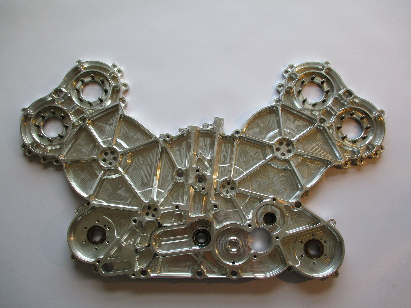
So onto the timing cover. On seeing it for the first time its lightness surprised me - it is machined from I would guess a 2 series aluminium and is left in its raw machined state.
If you have not yet seen an F1 engine - v8 or otherwise their smallness is always surprising. The timing cover in this thread is a great piece to display the engines compactness since it spans nearly all of the engines cross-section.
I'll first show a few general pictures of the part, then dive a little deeper into some of its finer details after.
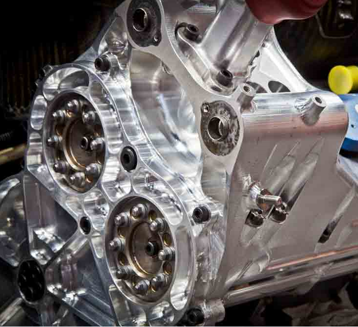
The front side of the cover shown below - this side of the cover is facing the drivers back and also houses the oil tank for the dry sump system. The fully dressed engine below shows tank and also the timing gear cover. There were a few versions of this engine over the years so my cover may differ slightly.
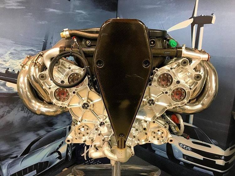
(Image Credit - Stew.Mitch via instagram - Public domain)
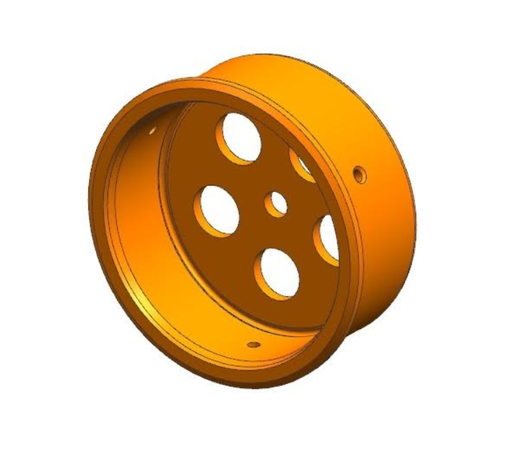
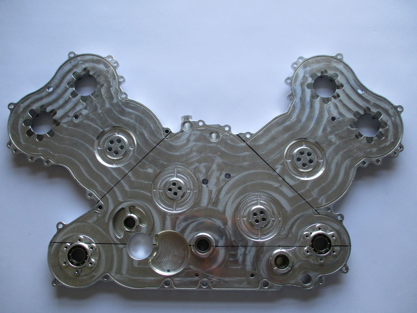
And the bare cover,
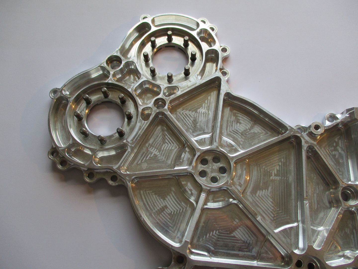
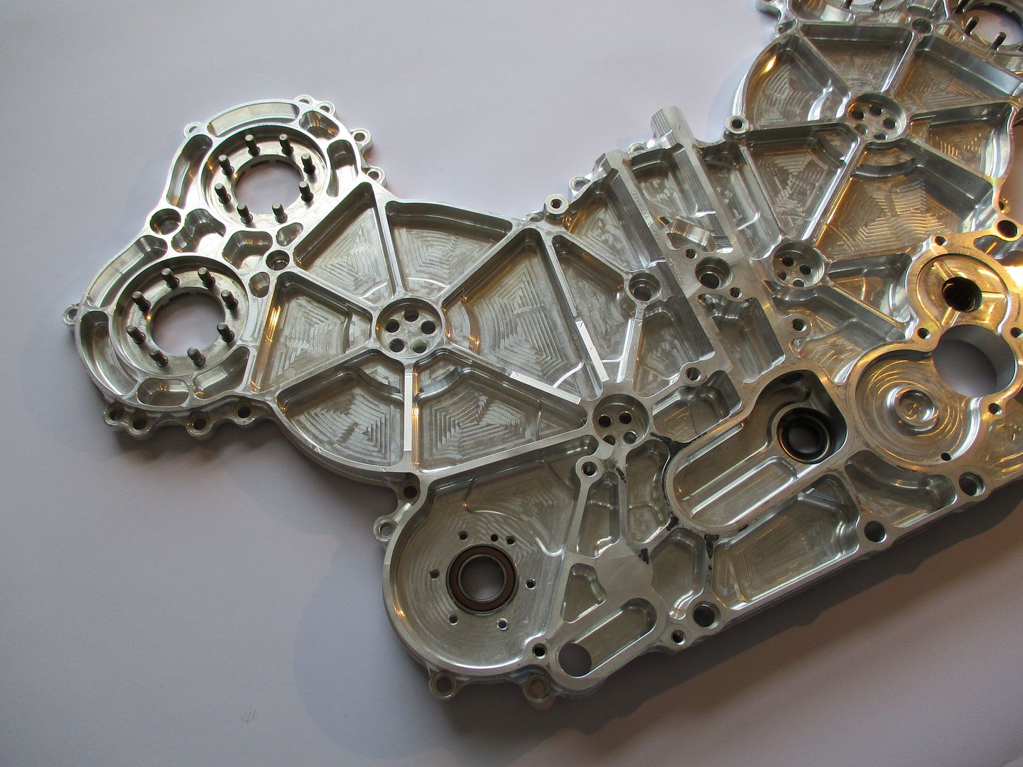
A close up of the machining detail, large step overs here - high fidelity not really required here really so long as material is hogged way for lightness,
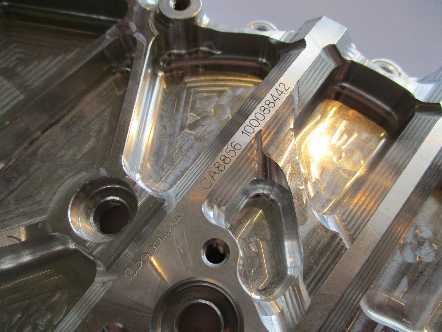
The ribs extending out from the timing gear shaft bosses ramp down,
Looking closer at the tooling marks, plus a few other machining details I would think this was machined on a 5 Axis machining center. It would make a lot of sense to do so on a part like this due to the high number of features on the edges, and at various angles. Multiple fixturing on a 3 axis machining center can allow tolerances to slide a little.
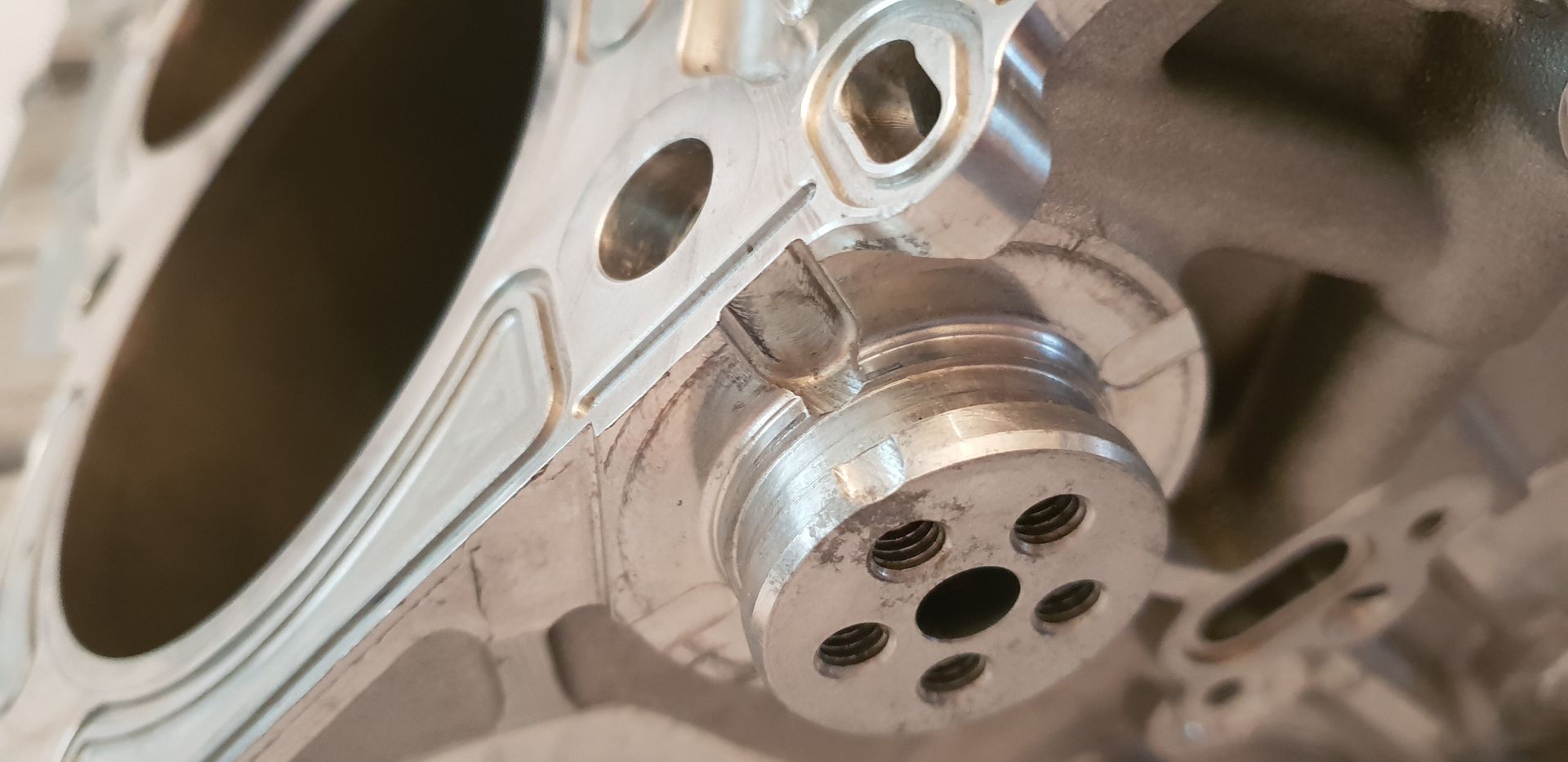
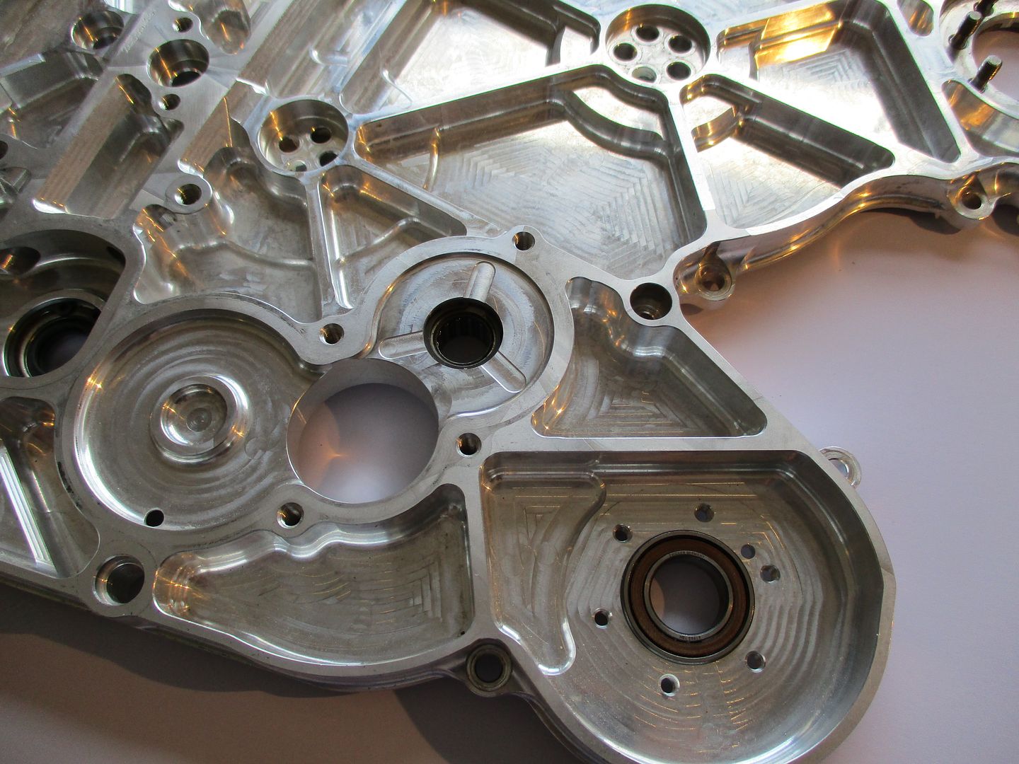
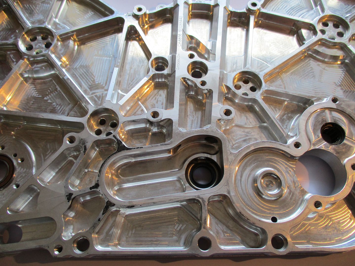
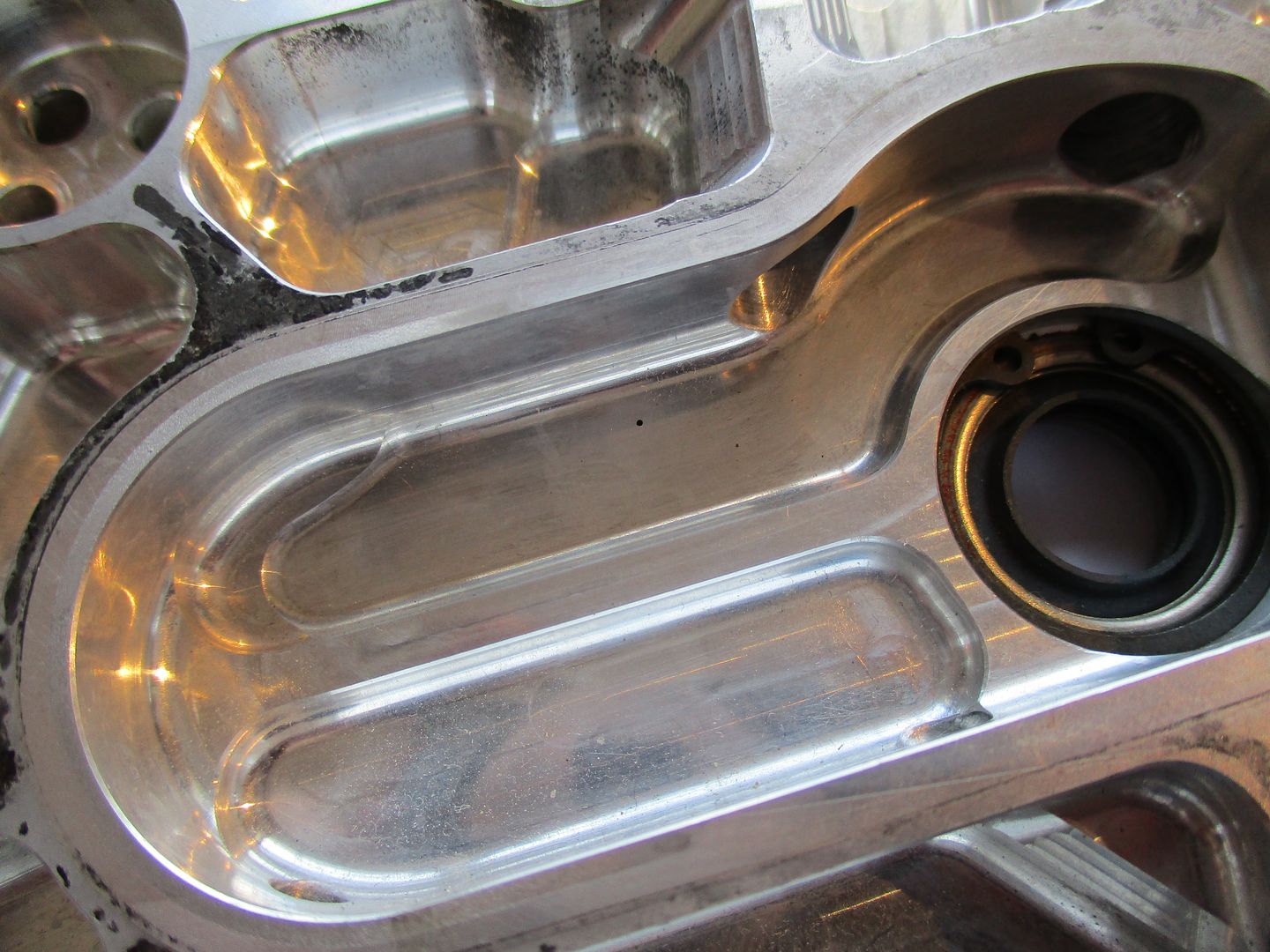
A closer shot of the main crank seal shows it is a double lip layout. Its important to note that the crankshaft big ends are supplied with pressurized oil through its nose from a high pressure compartment within the timing gear cover. Therefore, the seal arrangement has to hold back the high pressure oil from entering the sump around the crank nose, and also contain the vacuum present within the sump from the oil scavenge system. So this seal is critical on both sides.
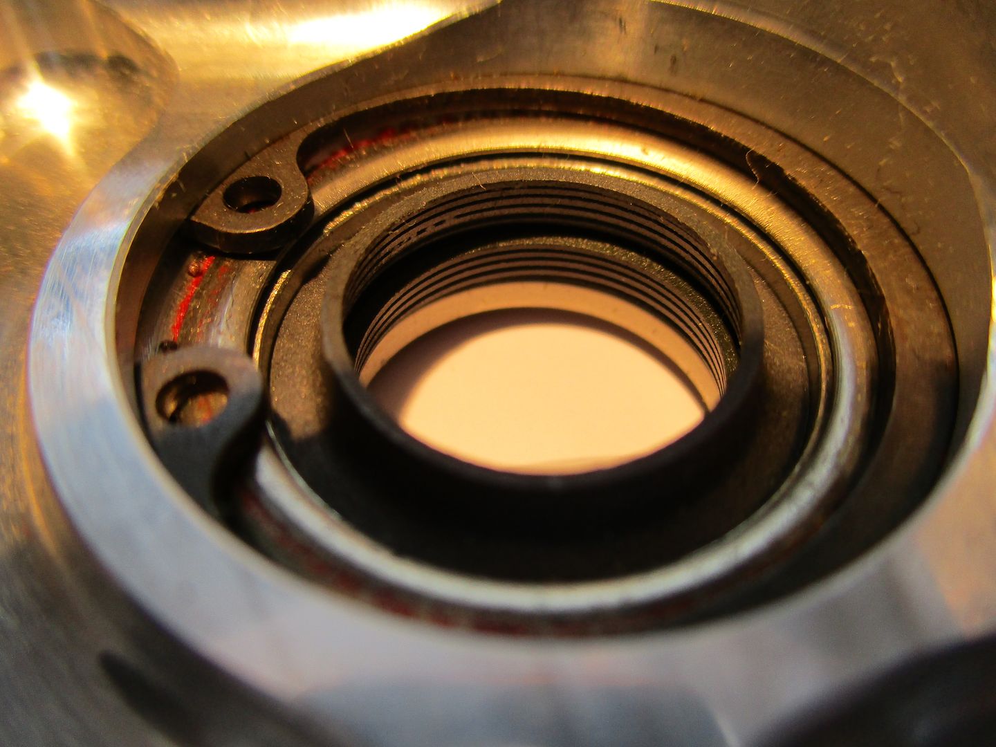
A larger shot of high pressure compartment the crank nose exits past the seal into,
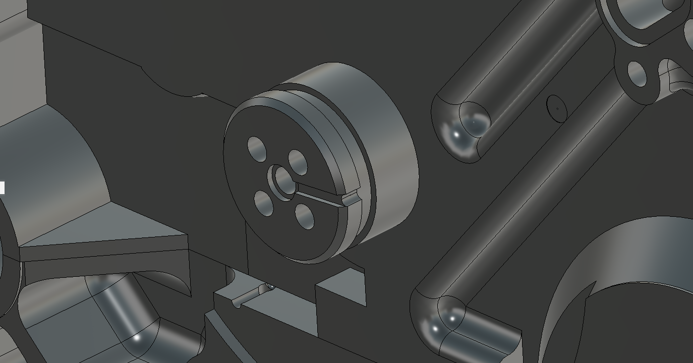
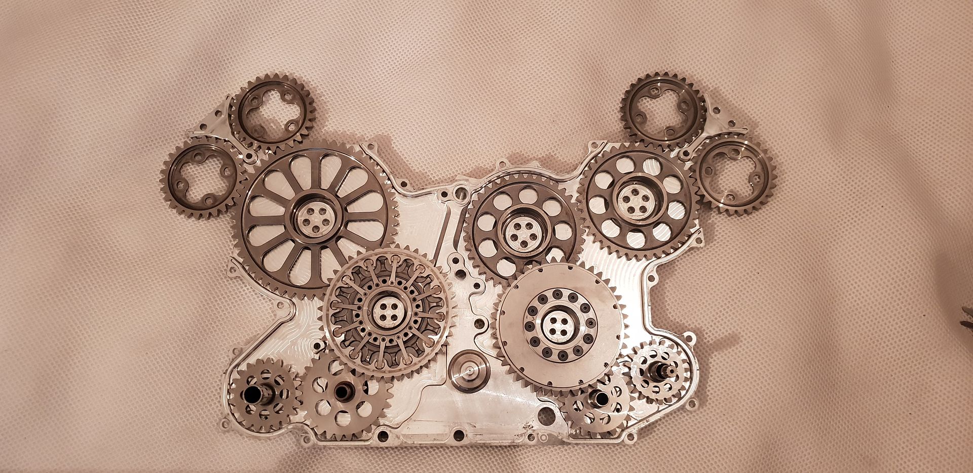
A shot of the same engine and extended crank nose/drilling as well as the gears which I'll be touching on again later,
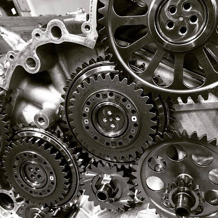
(Image Credit - Luke_Bywater_ via instagram - Public domain)
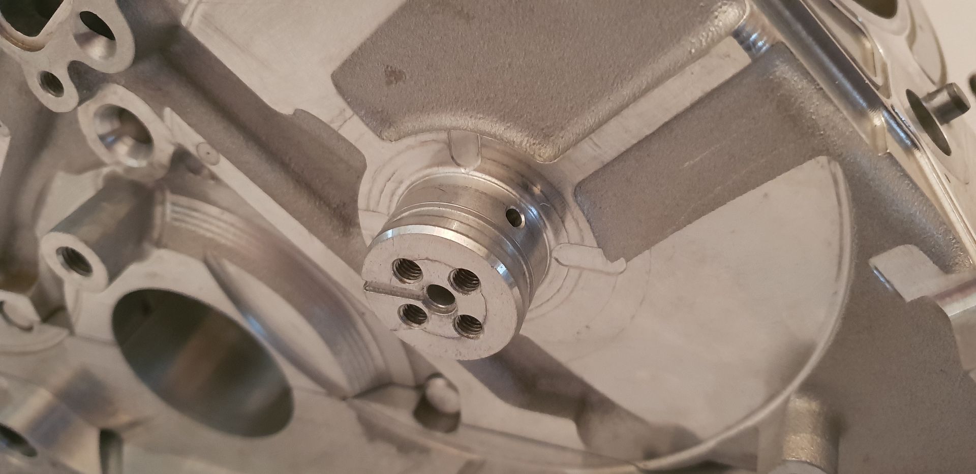
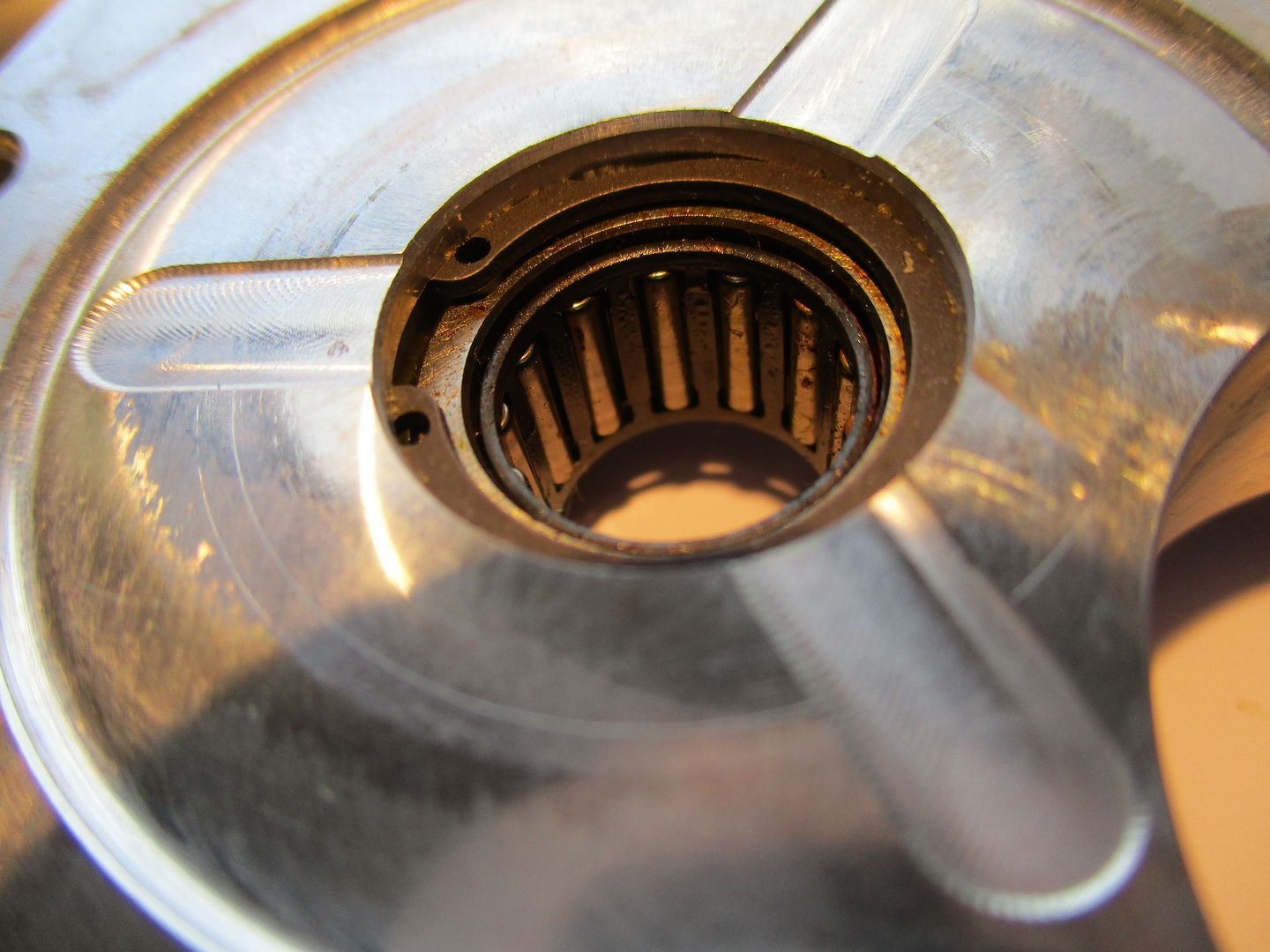
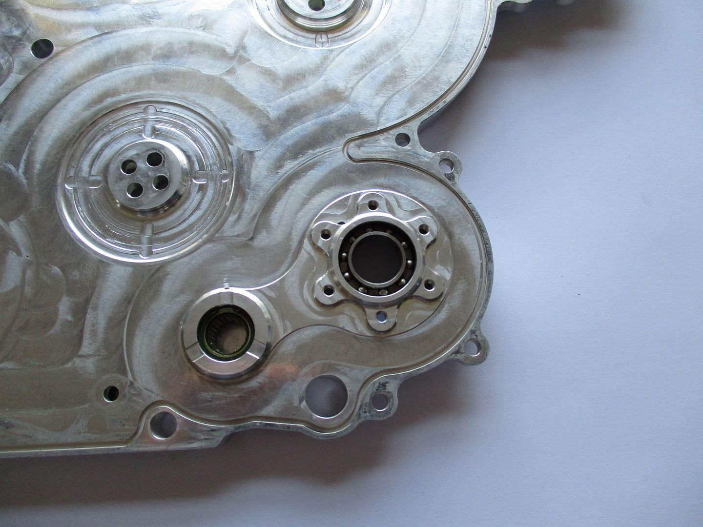
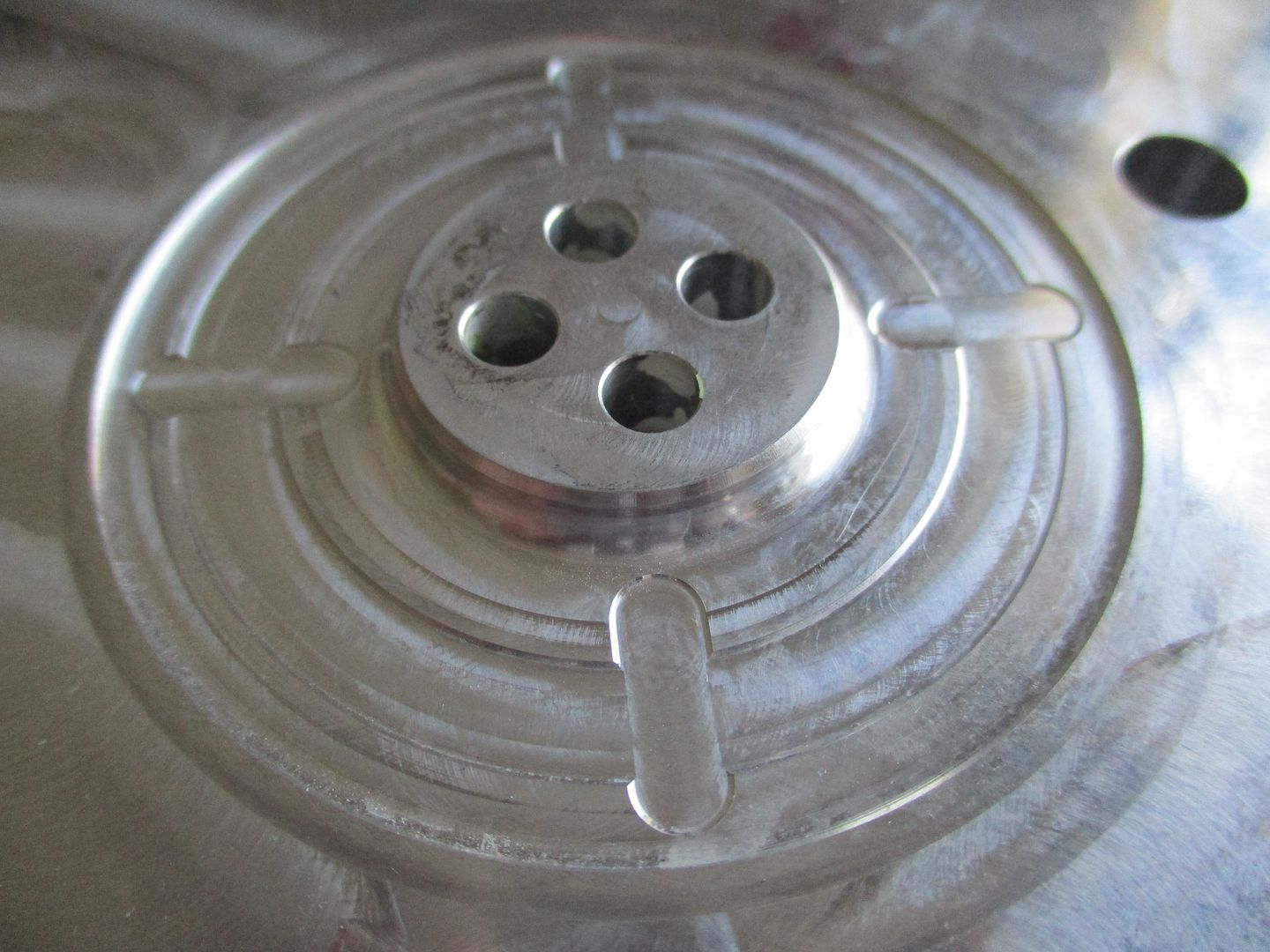
A closer shot of a needle bearing housed in the cover as well as a thrust face. Notice the pockets in thrust face for oil as well as a place for foreign objects to collect and exit should there be any present. On observing the needle roller bearing its apparent it is installed the wrong way around. Normally, you would always install any bearing with the size or part number under the cir-clip or other method for holding bearing in. Installing it this way allows the technician to remove just the cir-clip or nut, view part number/size, and either order, or check to see if it is in stock. If the bearing is installed with the part number facing in, the bearing has to be removed to get the number off it - putting the engine out of service. I will say however I'm pretty sure these guys know all the sizes of everything in these engines without having to do a visual inspection but it is always worth keeping in mind for the technician you may never meet coming after you - especially in critical applications or bespoke designs.
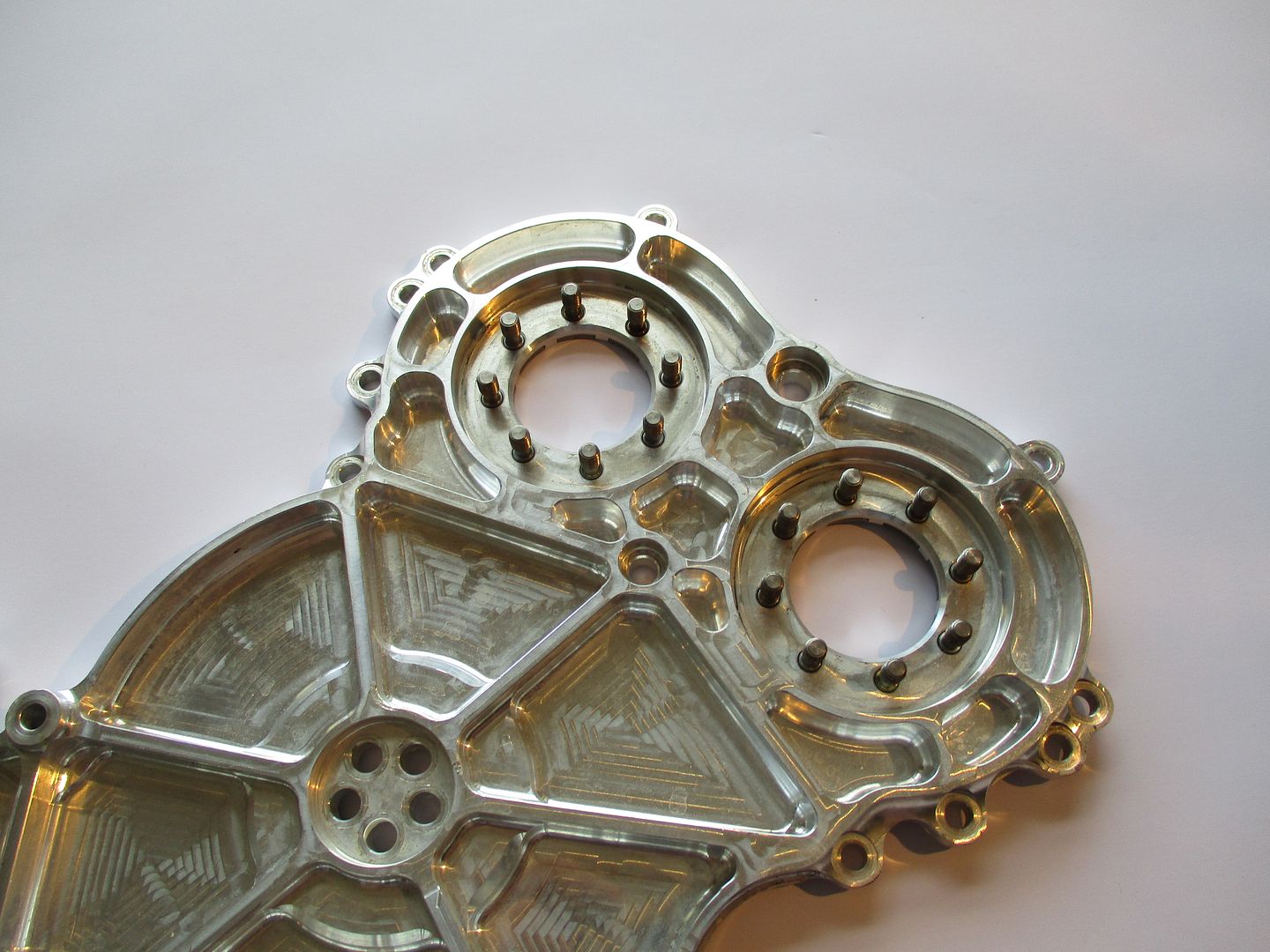
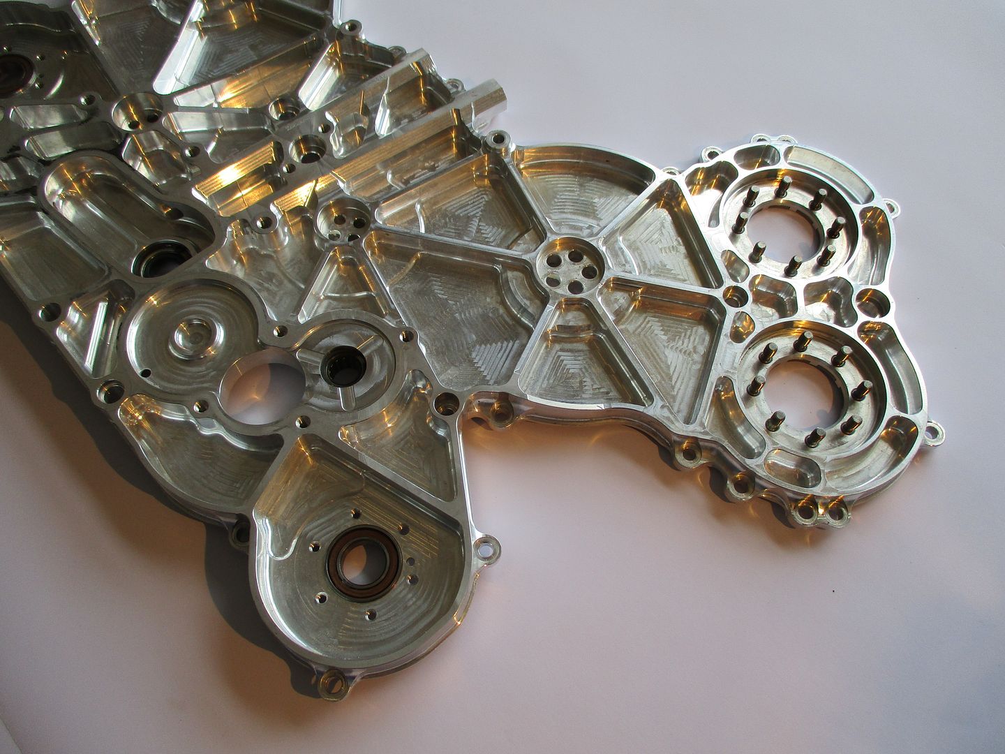
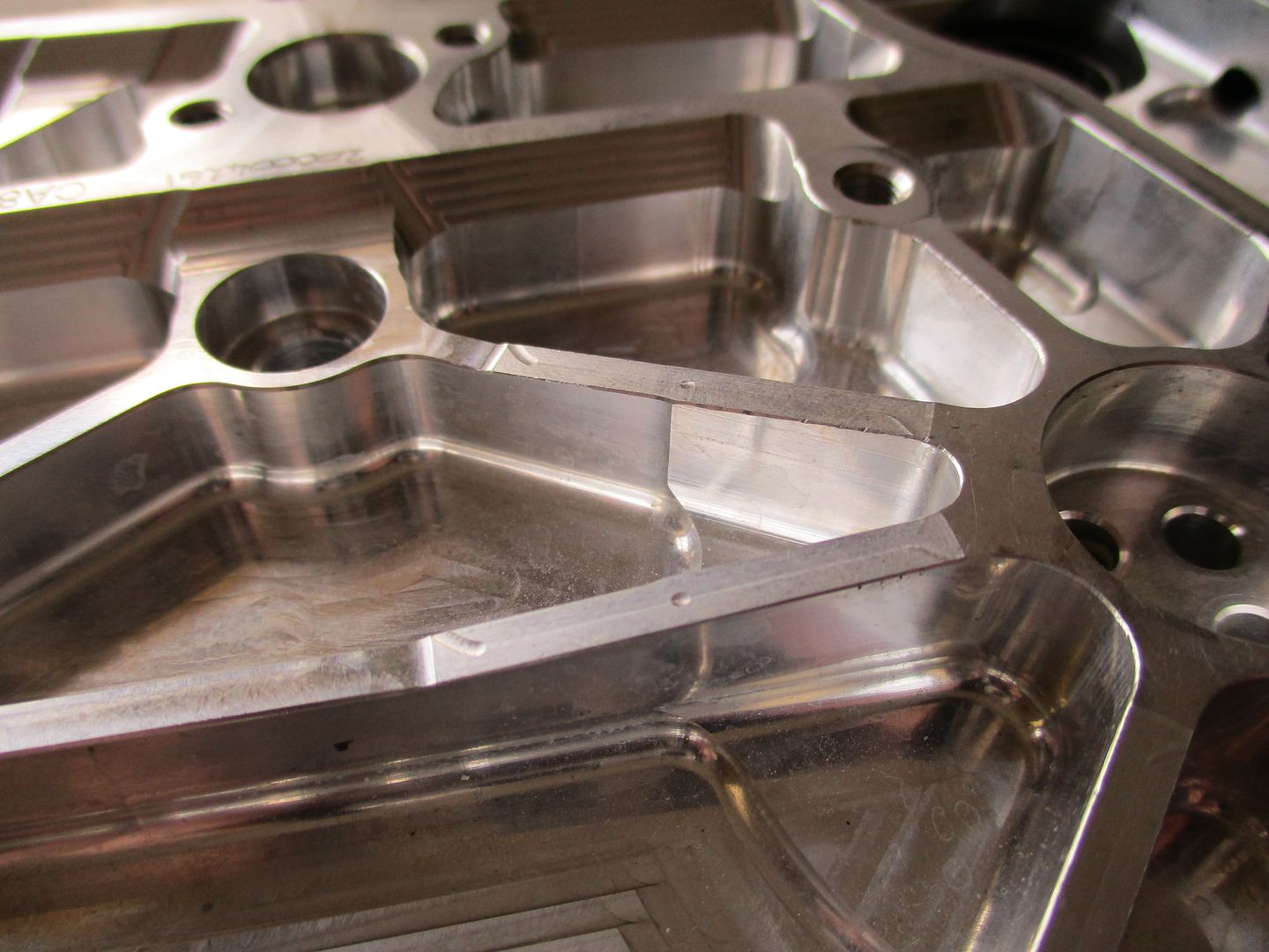
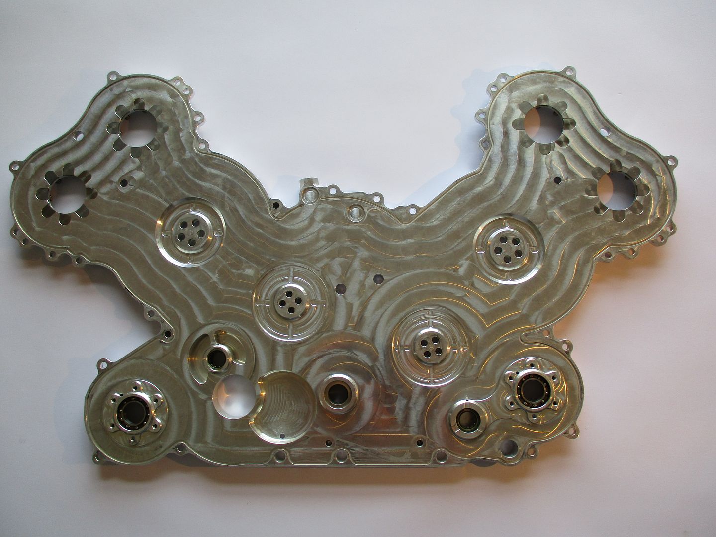
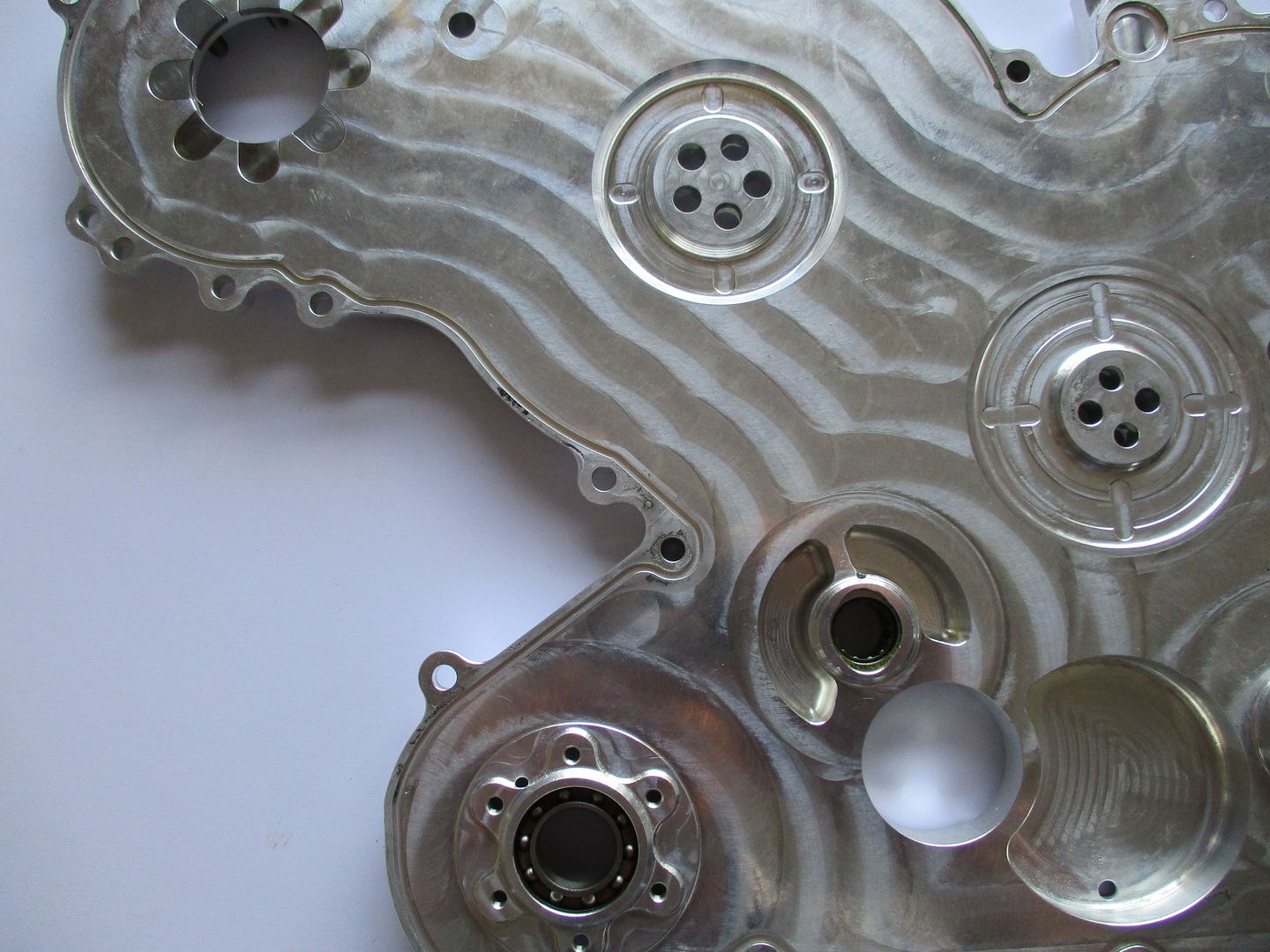
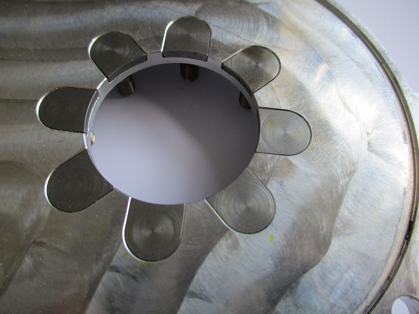
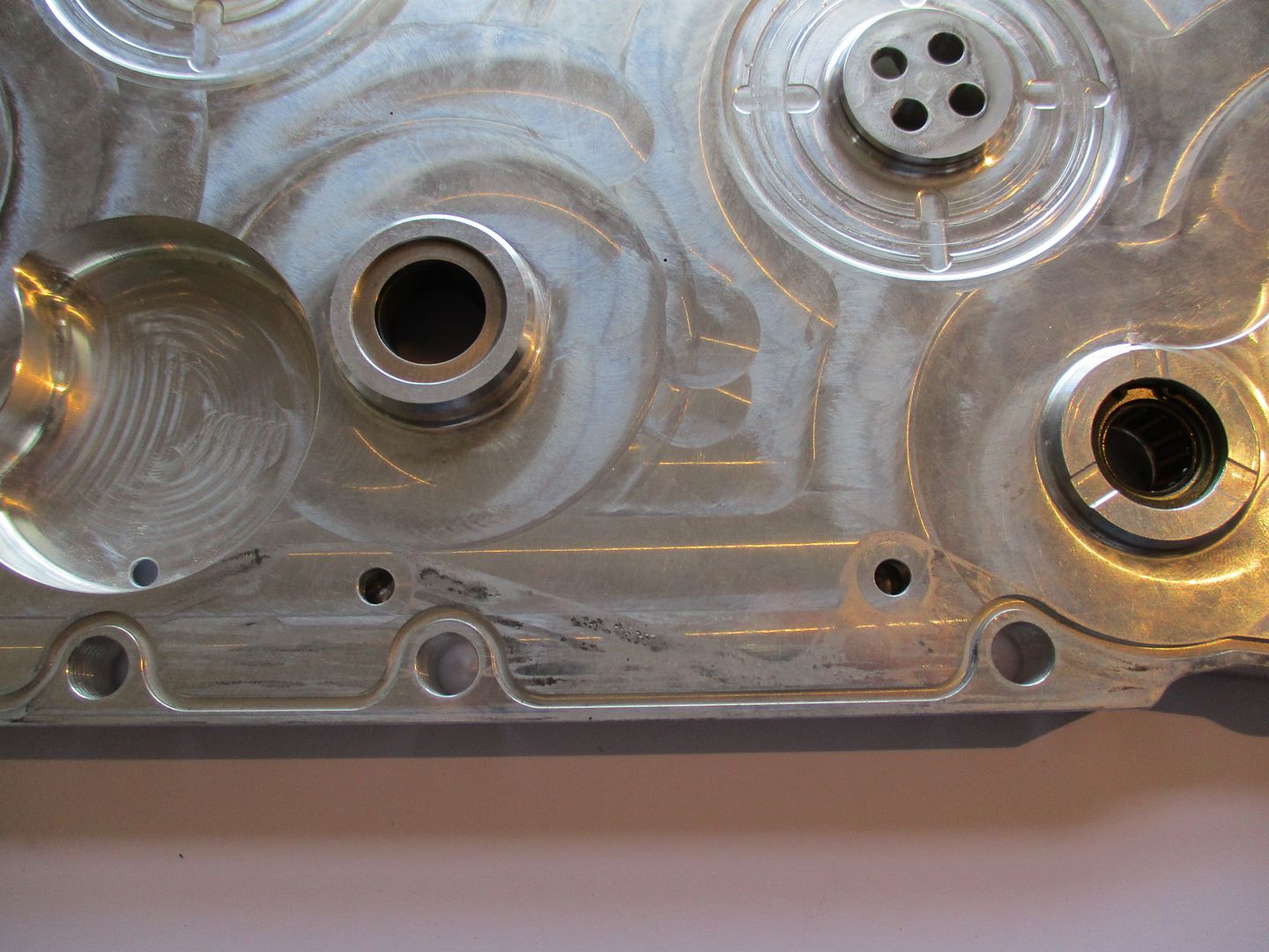
Flipping over the cover we can now take a look at the inside - this is the side that faces timing gears,
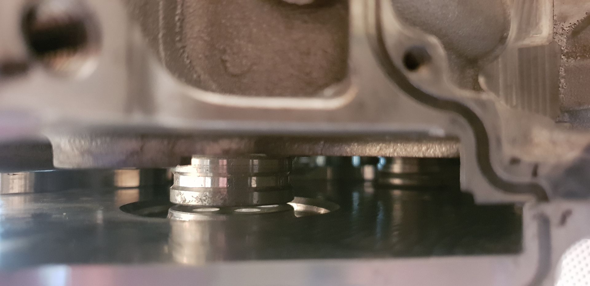
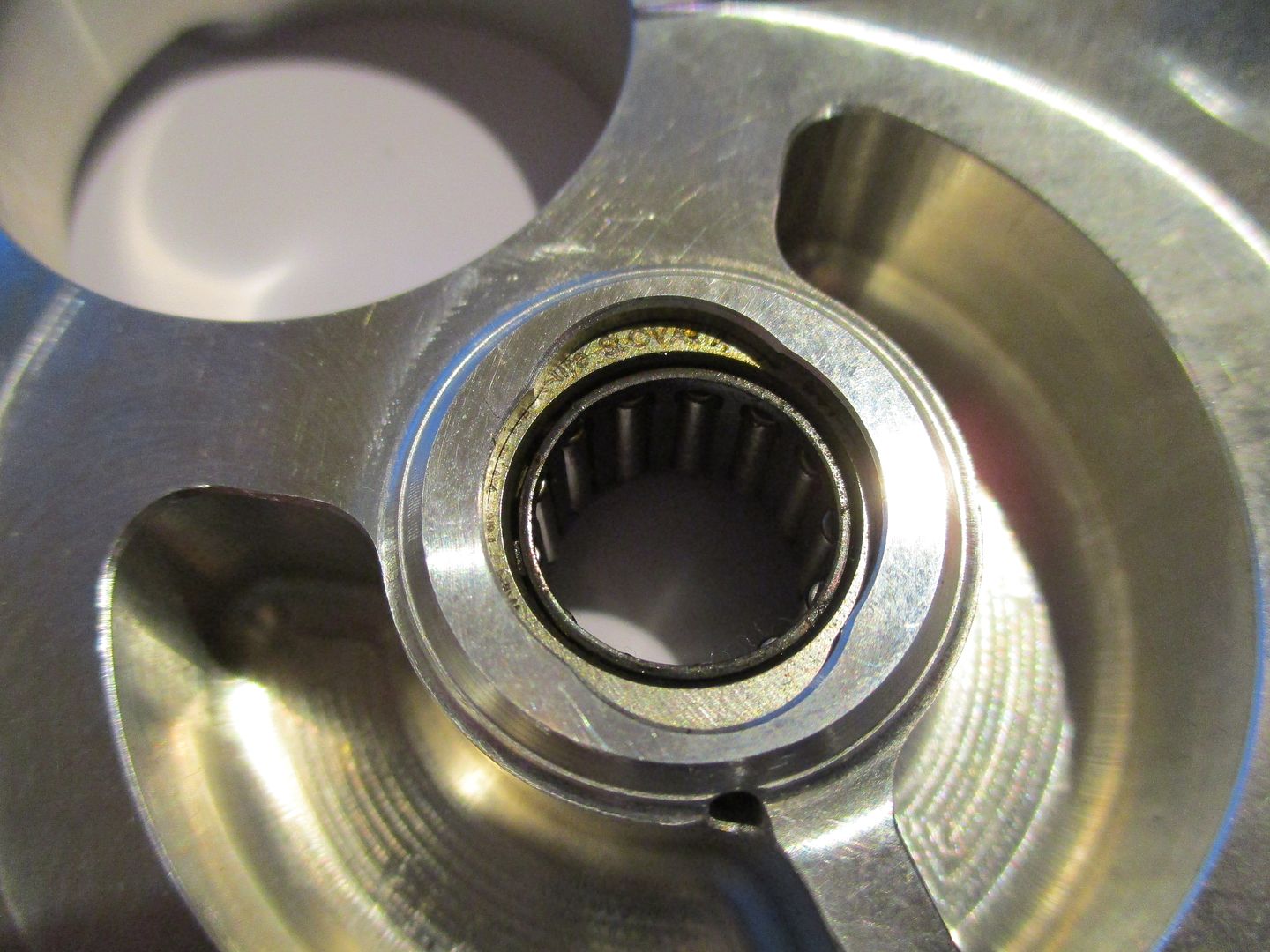
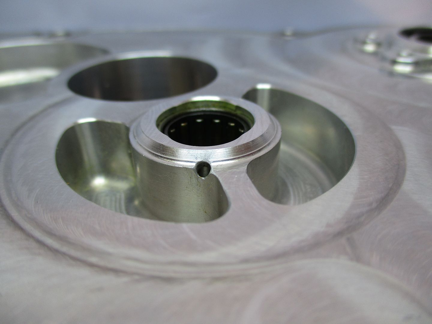
A closeup of the needle bearing again mentioned above - part number face in against housing side, also worth nothing the drilling to allow oil mist in generated by the timing gears,
The back side(heads) of the bolts used to secure cam endcaps - fully bespoke items,
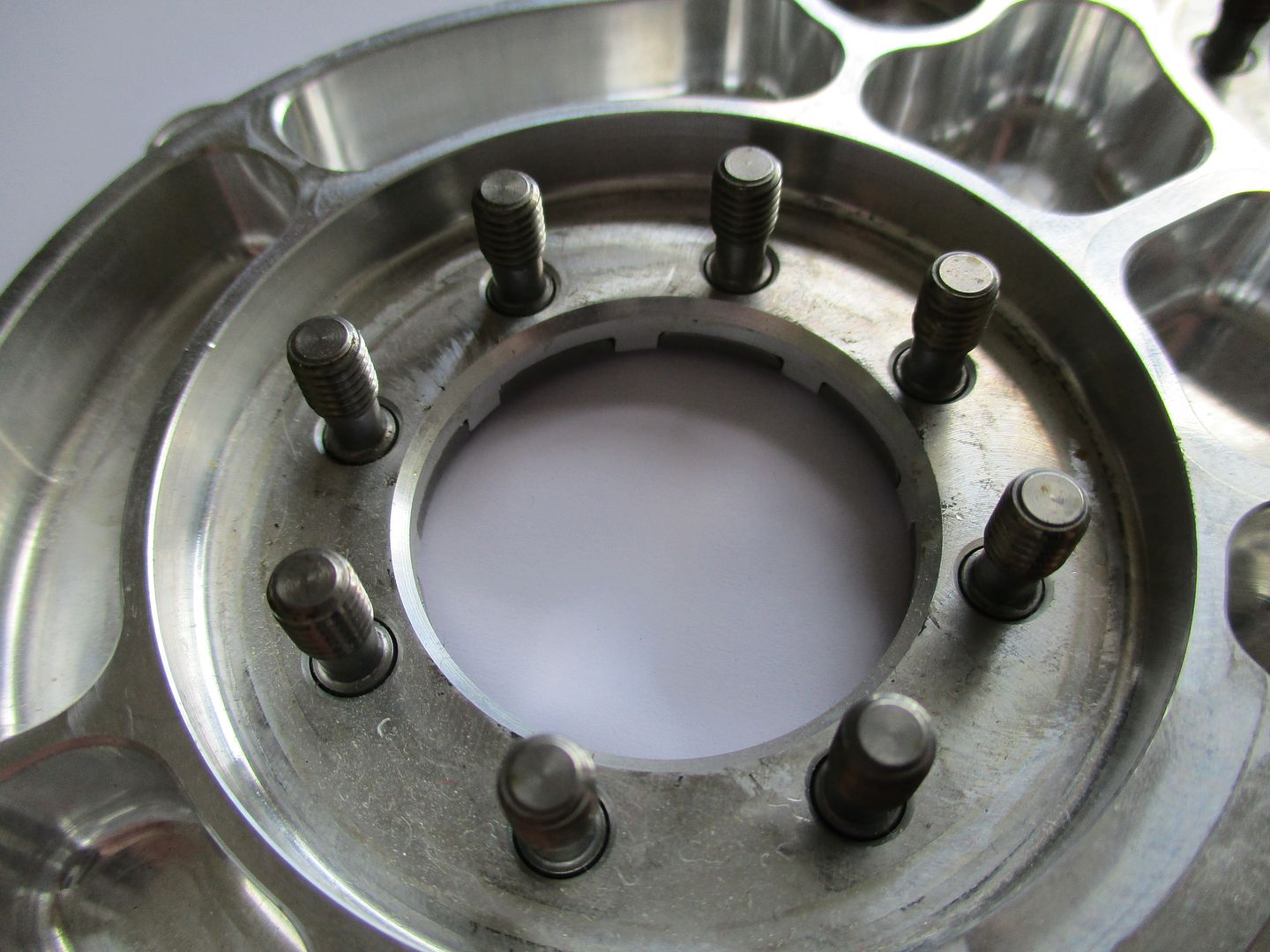
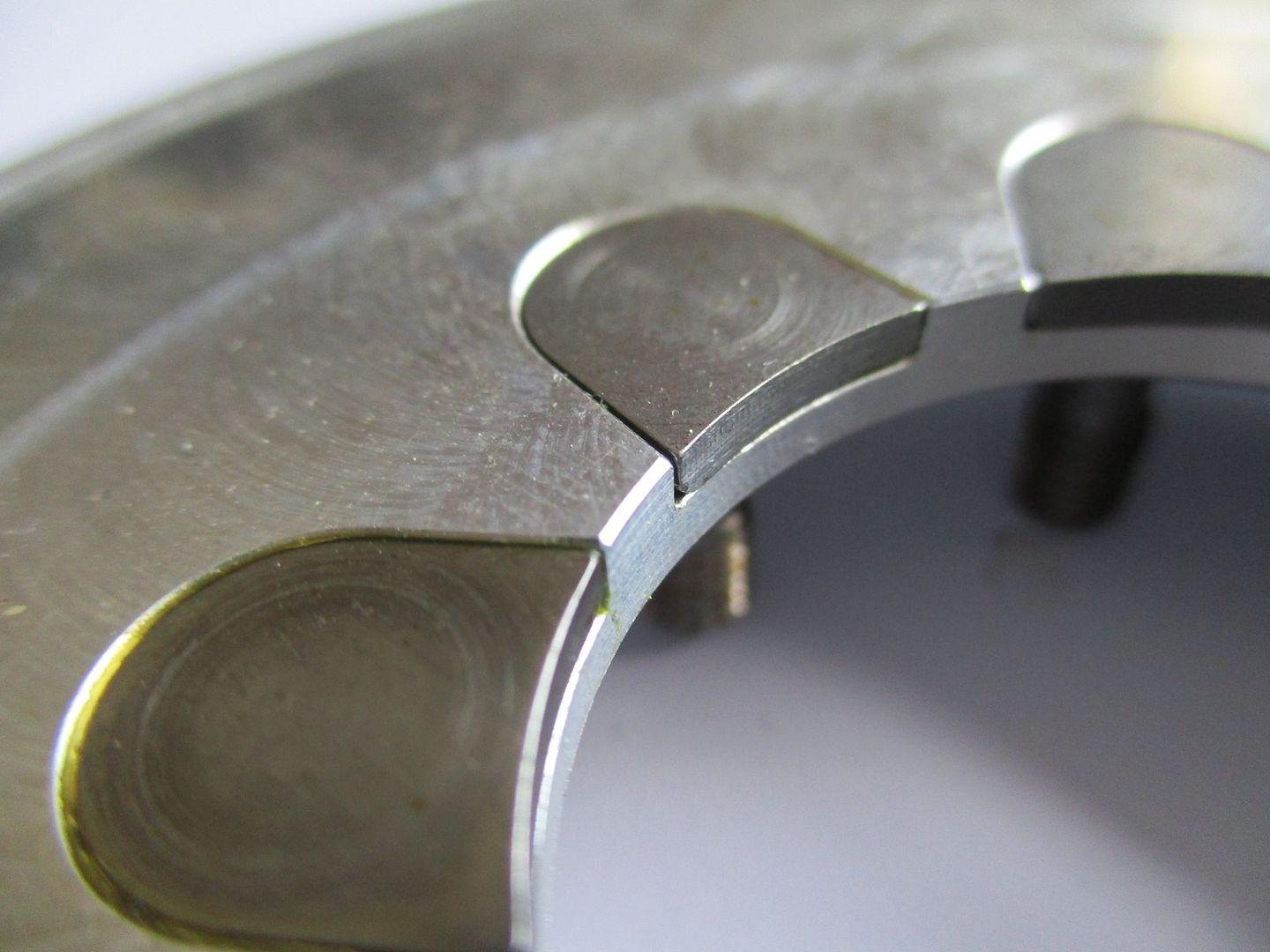
The locations where the timing cover bolts up to the timing gear shafts - these also contain thrust faces to control any axial end float present in the gear train. Since they are straight cut gears axial forces here are low - g-forces acting on the gears themselves due to braking being the main forces on these surfaces.
Resorting back to the image below, you can see the gear shafts, as well as the wear pattern rings on the gear faces from touching the cover,
(Image Credit - Luke_Bywater_ via instagram - Public domain)
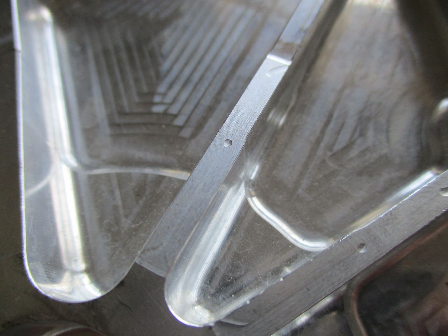
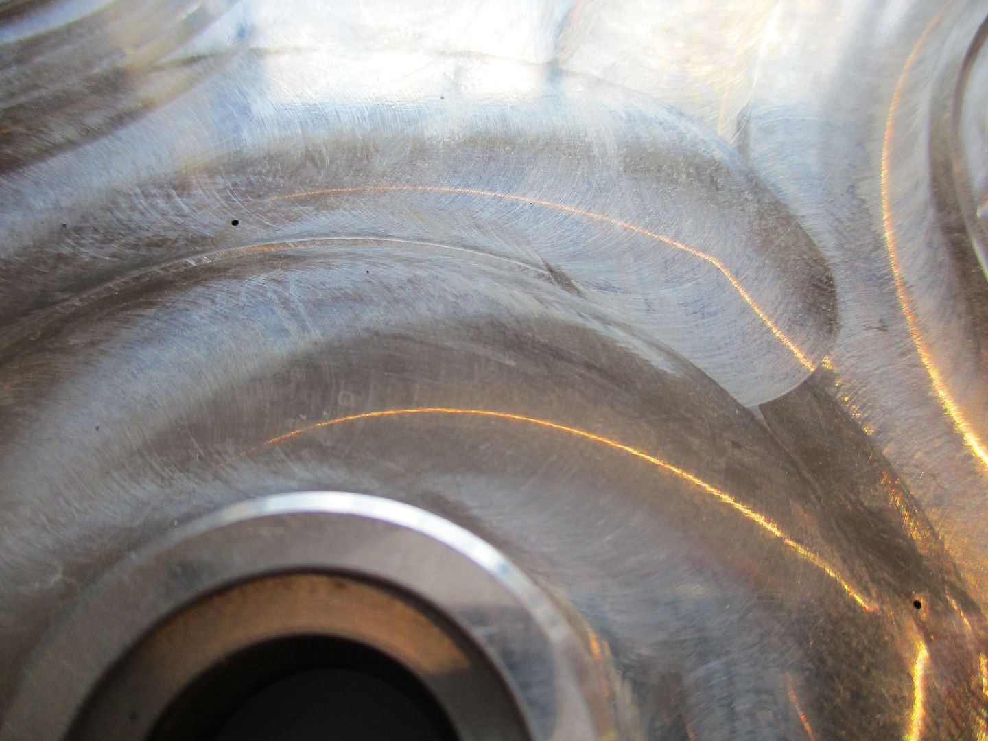
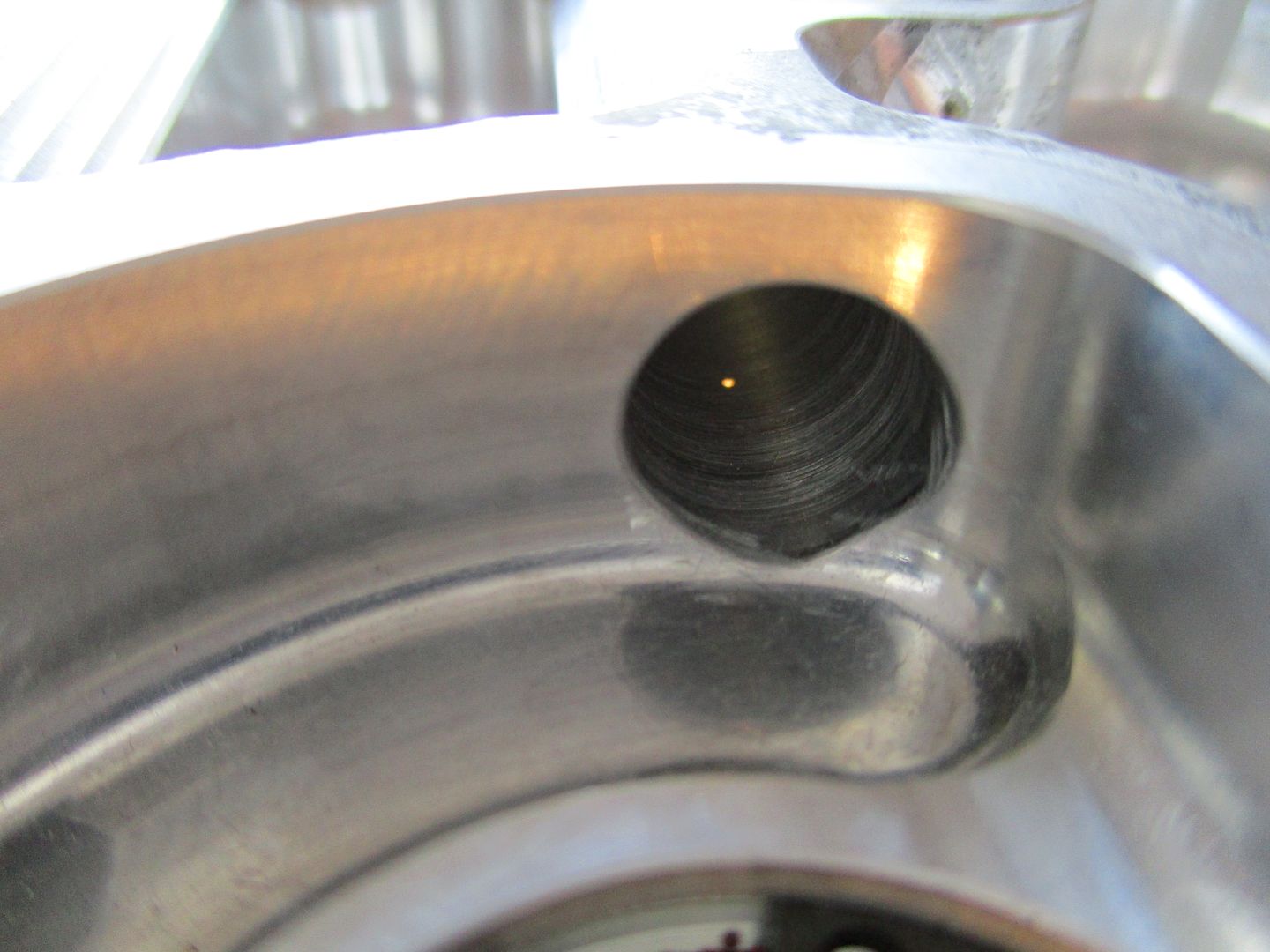
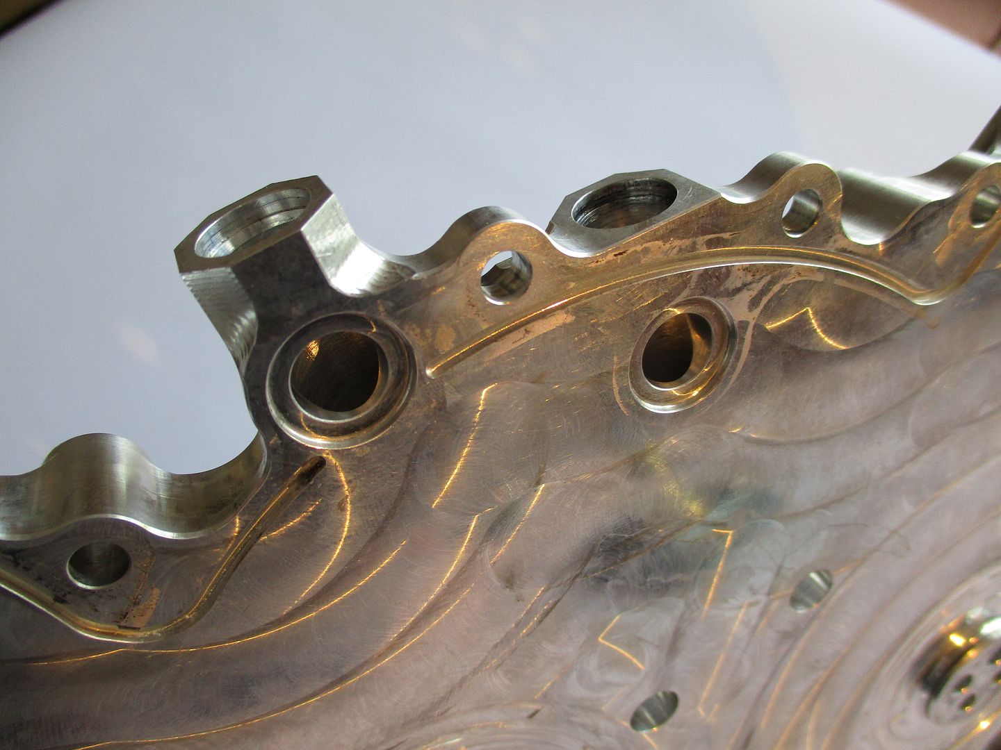
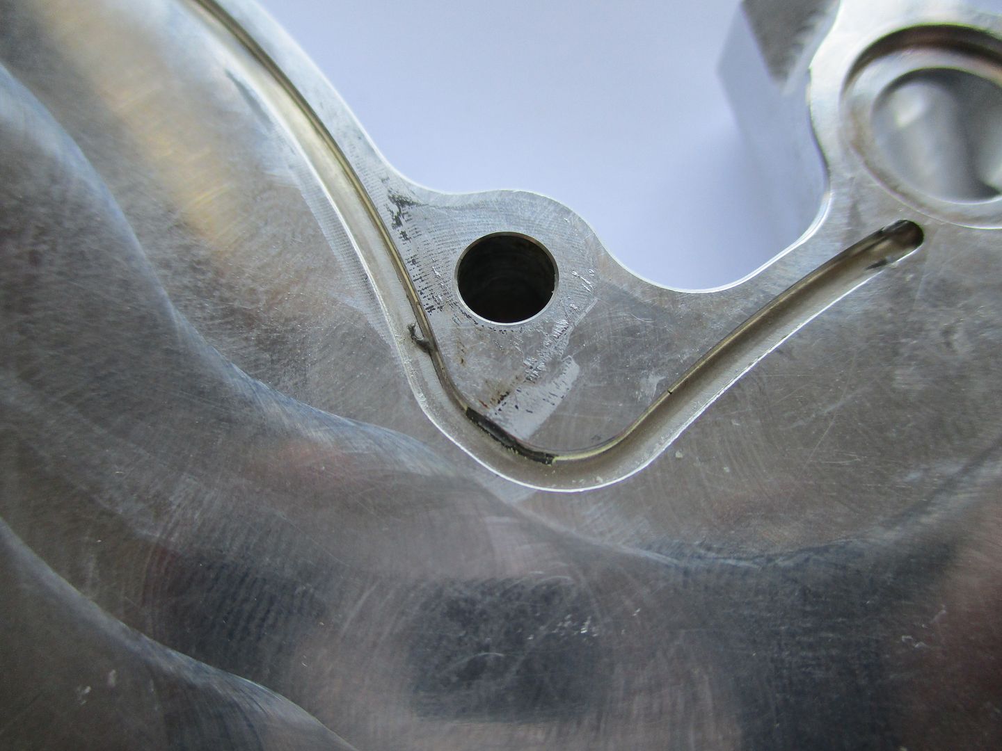
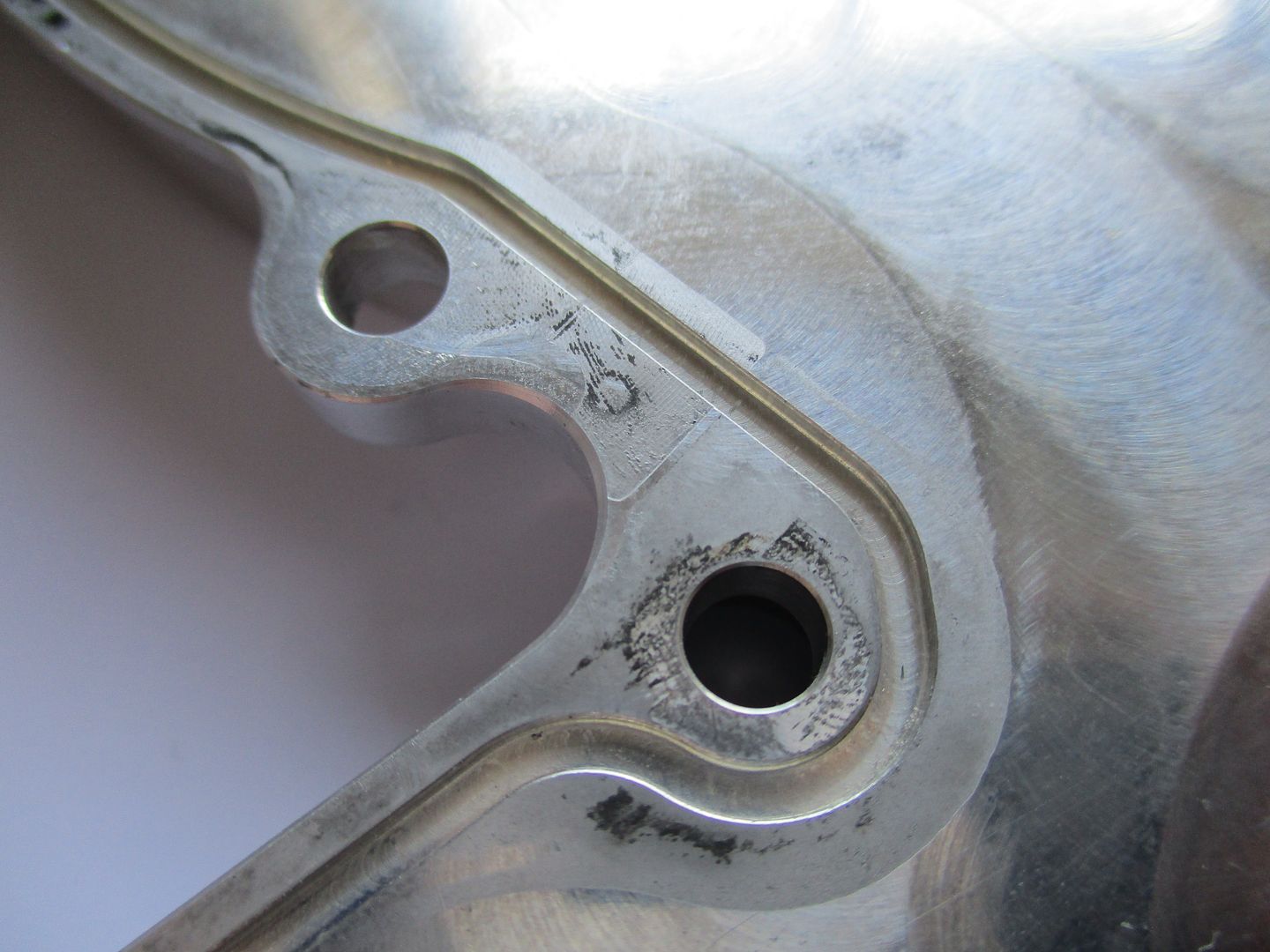
Obviously all of these gears need oiling. Originally I had thought that head drain back oil to sump provided the lubrication to the gears but on closer inspection this was not the case. It was in the 4th hour of closely inspecting the timing cover prior to the photo-shoot that I figured out how they did it. Oiling to the gears is done with two very small holes drilled into the ways within the cover that go to the Cylinder Heads. The holes are extremely small and at first I thought they were porosity and that the cover was machined from a near net casting.
The holes shown below, they are approximately at the 11, and 2 o Clock positions 25mm out from the crank center,
Ok so a little closer then...
They are roughly 0.22mm in diameter,
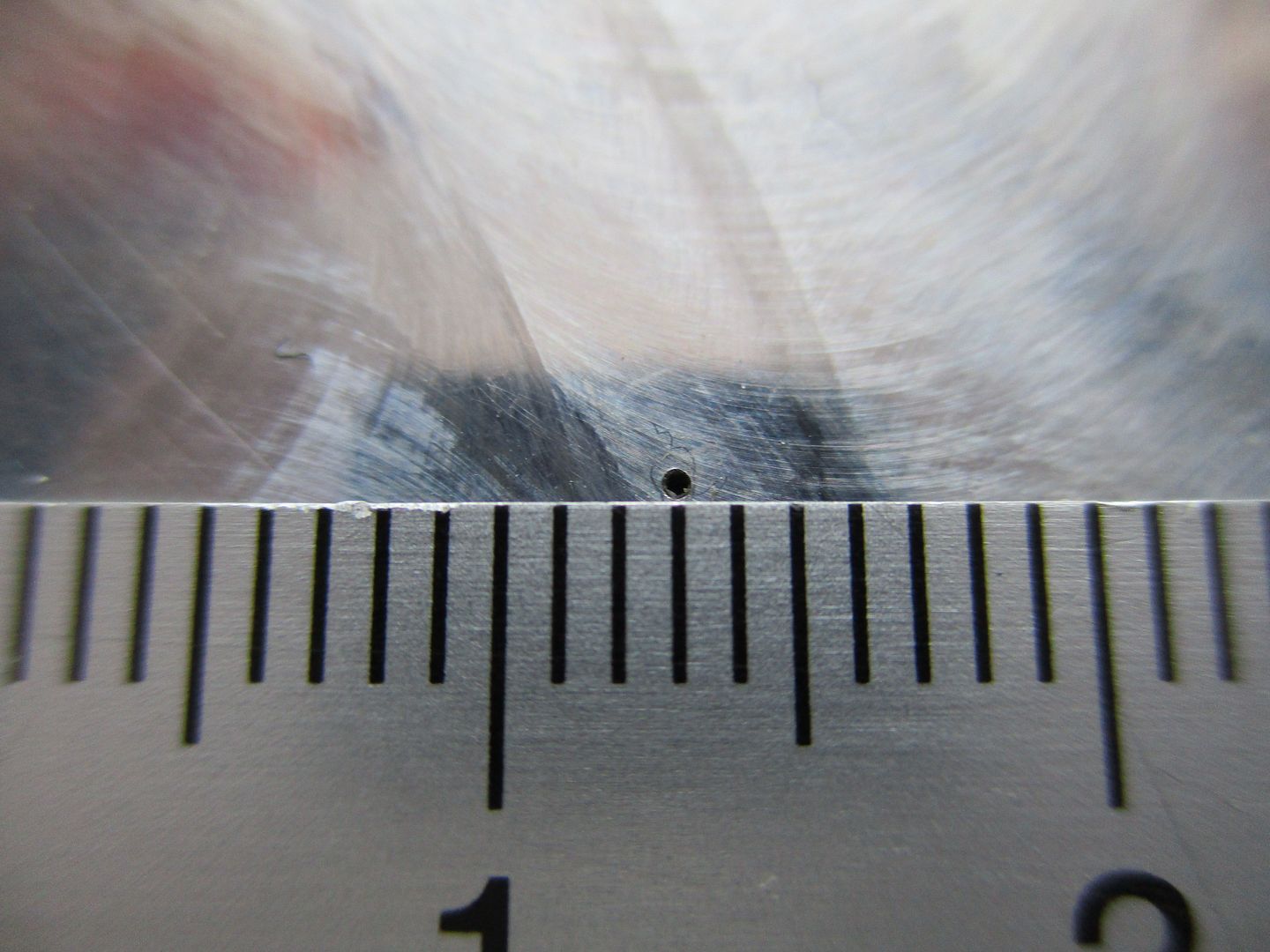
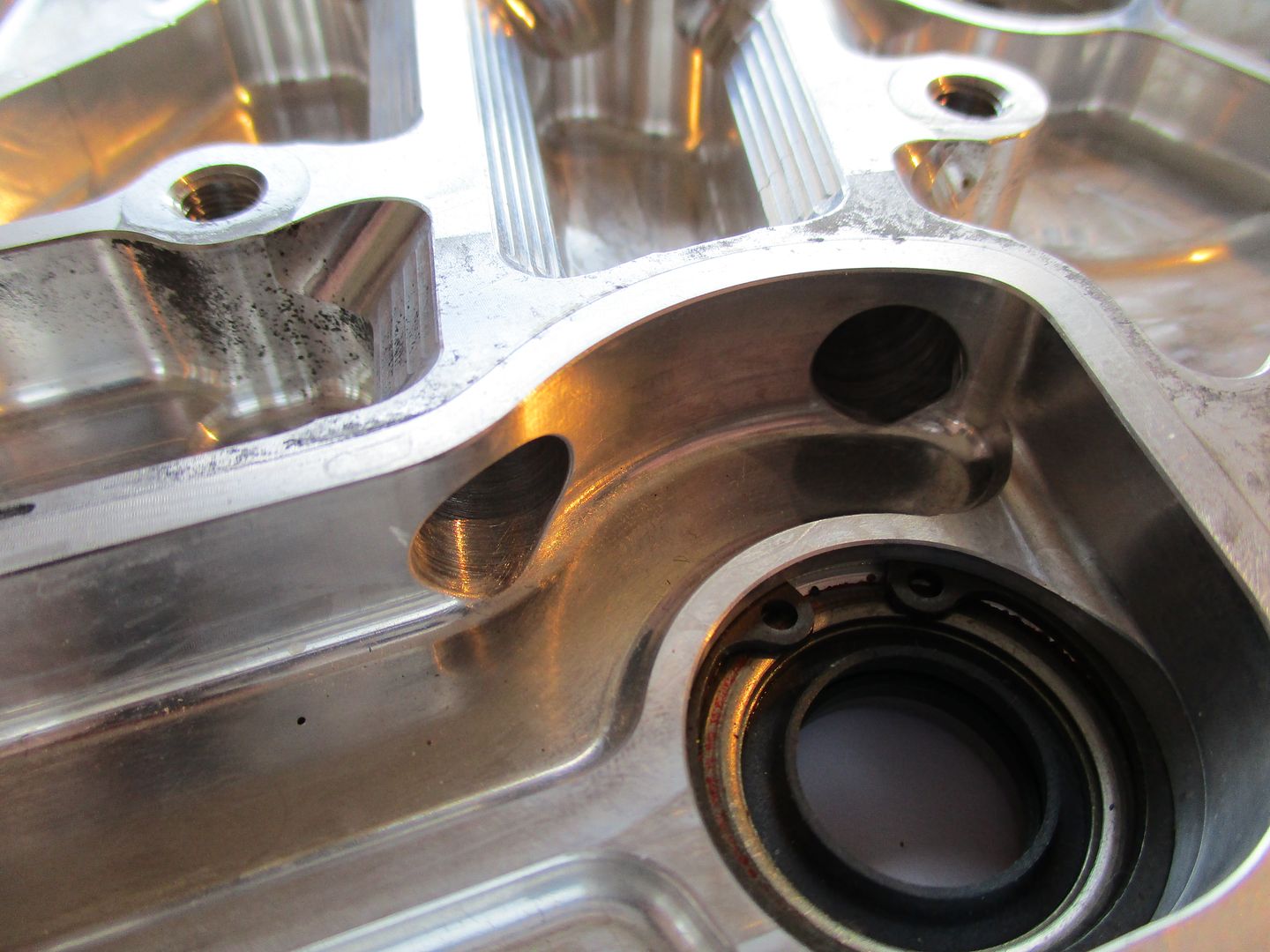
One enters the high pressure compartment that supplies crank/block/heads as mentioned earlier(middle of 1st image below), the other enters one of the drilling extending up to the head,
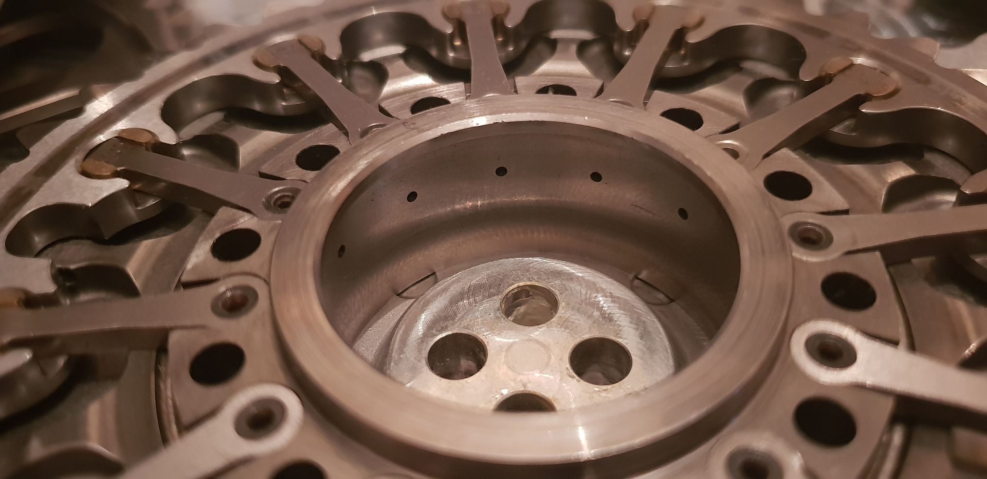
They spray oil directly into the mesh points of the crank gear shown below at the 9 and 12 o clock positions,
(Image Credit - Luke_Bywater_ via instagram - Public domain)
While we are on the topic of oiling, lets take a brief look at the drilling's exiting the high pressure compartment.
Turning the Timing cover over again to show compartment once again,
The drilling's up to heads,
And a shot showing where they exit top of cover,
Two more ports also exit near the top of drillings, these feed the main bearings in block.
Looking at the bottom of the high pressure compartment two more drilling's exit,
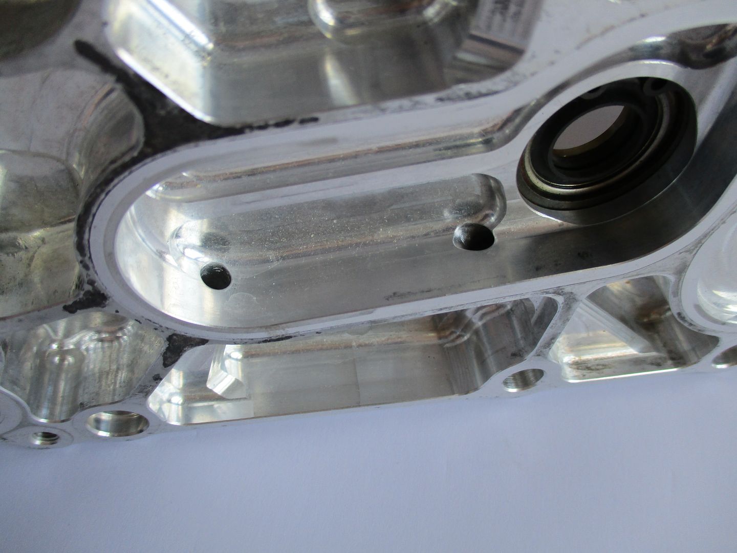
The drilling's are plugged at entry point,
And two cross drilling's intersect these and supply oil into the sump girdle, and onto the piston squirter's,
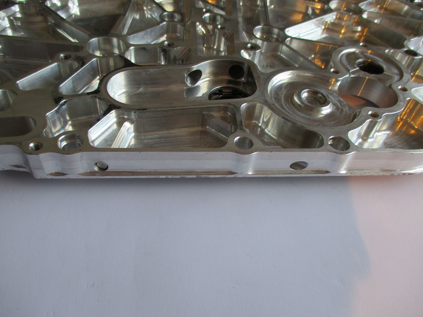
Moving onto the interface between the F1 Timing gear Cover and the engine itself some interesting things are visible.
Along the interface the print of the head and block join can be seen, as well as the block and sump girdle joins. A more interesting thing is the amount of galling at the interface that is present on the timing gear cover as shown below,
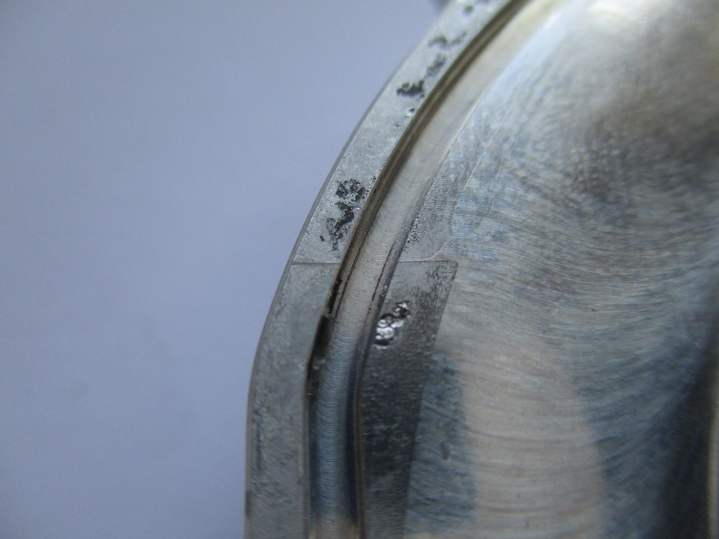
Since the engine is a stressed member and needs to contain huge amounts of power and forces as well as thermal expansion galling is not uncommon in areas such as the above. Galling occurs where there is high clamping pressure between two surfaces(the bolt clamp loads) as well as movement or micro fretting. It is a direct result of this friction and adhesion and leads to one material tearing up the other adjacent material - in this case the timing cover itself. If the engine block was on hand for inspection, parts of the cover above could be seen friction welded to the block end face. Because the block and heads have higher silicon content than the timing cover they would also have increased resistant to mechanical abrasion. Hence in this case the timing cover material is the one that is displaced.
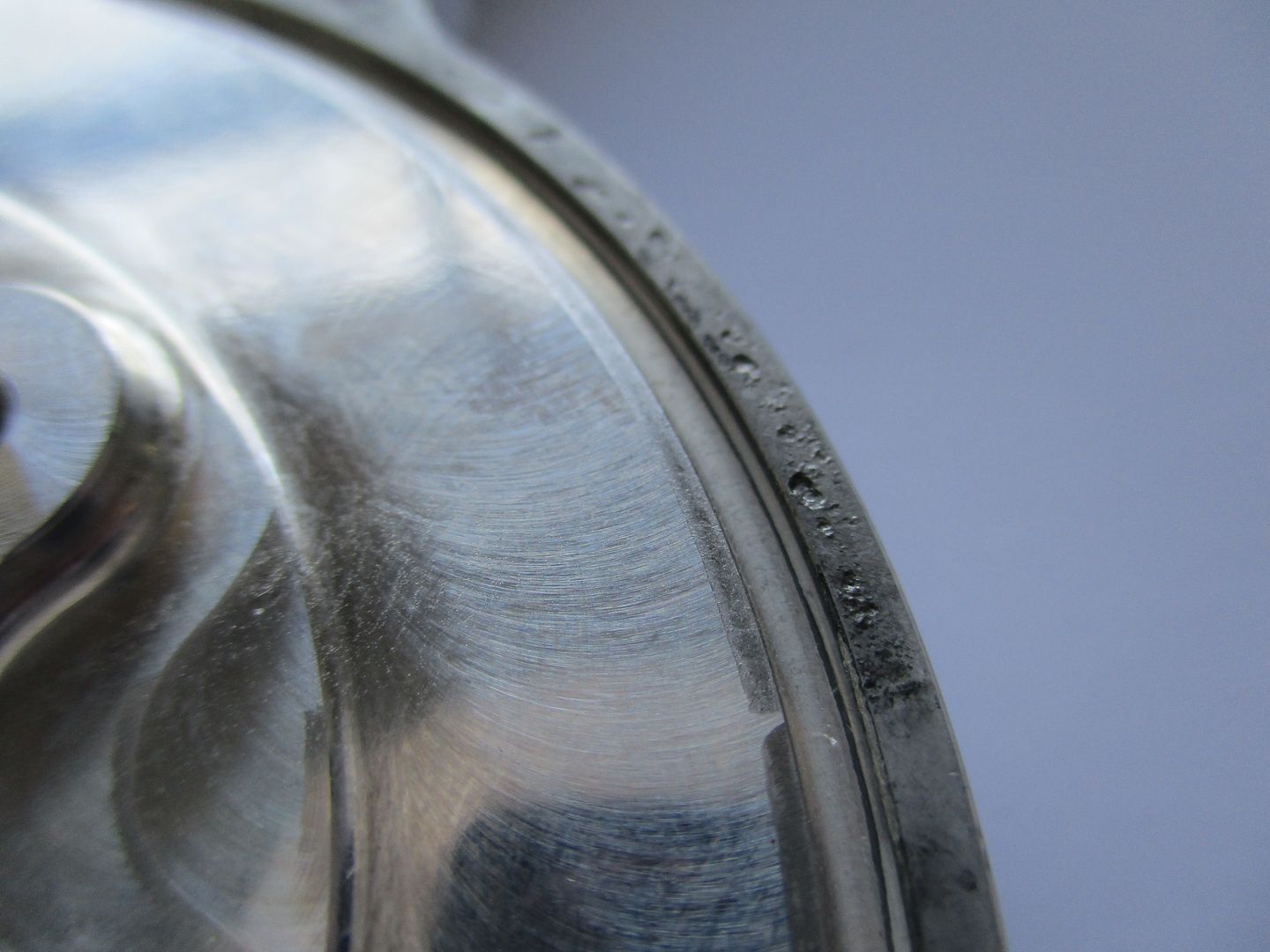
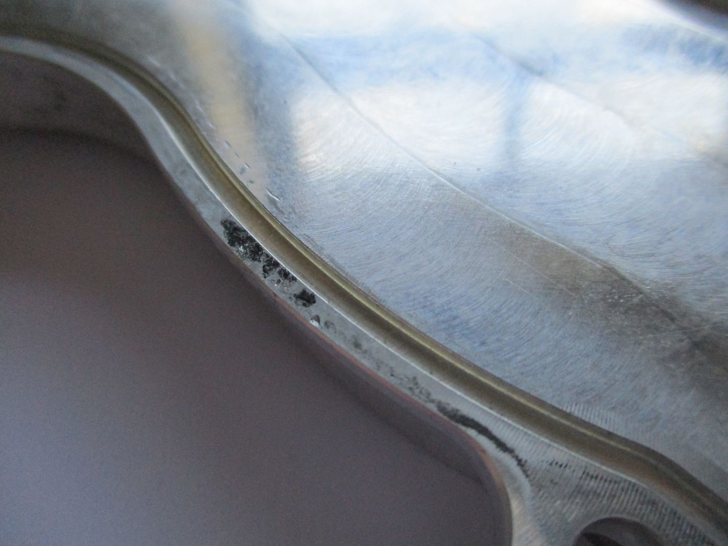
The head and block joins can also be seen printed on the inside of the timing cover due to this micro movement.
They are very faint but visible and approx 4 microns high,
Using these witness marks the head and crank girdle lines can be established and marked onto cover,
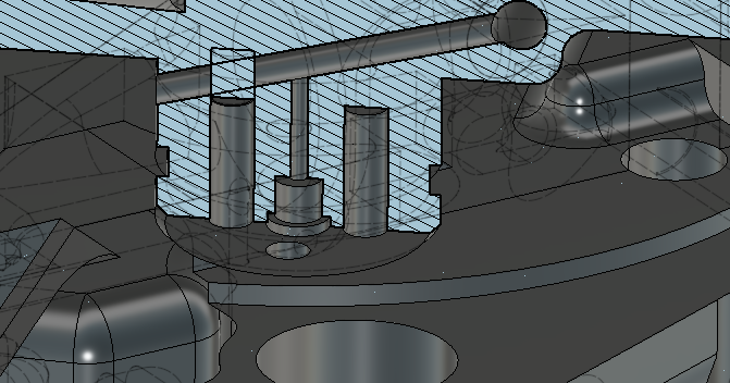
The Piston, Pneumatic Valve Spring and Finger Follower can then be placed down to illustrate just how compact it all is,
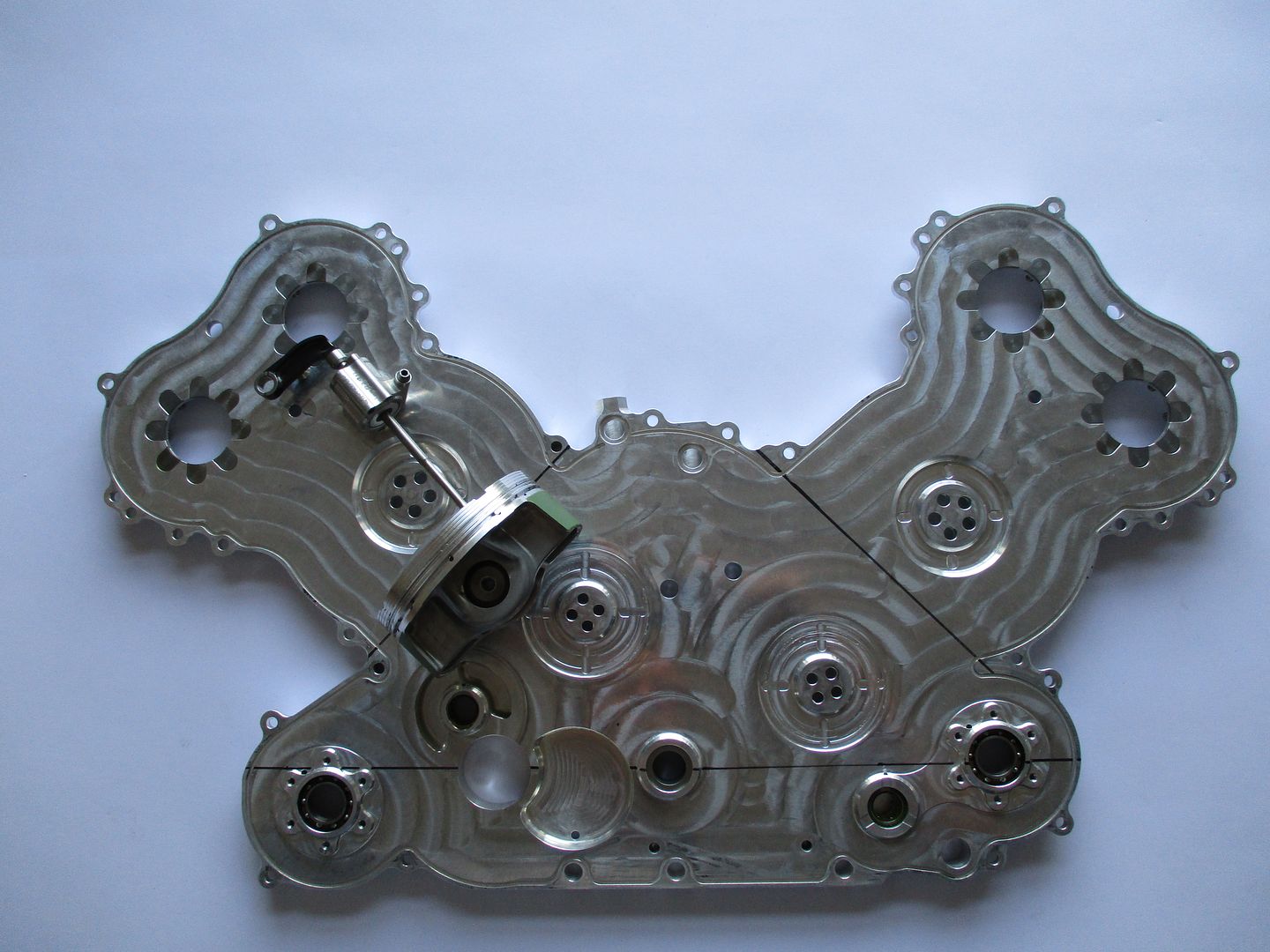
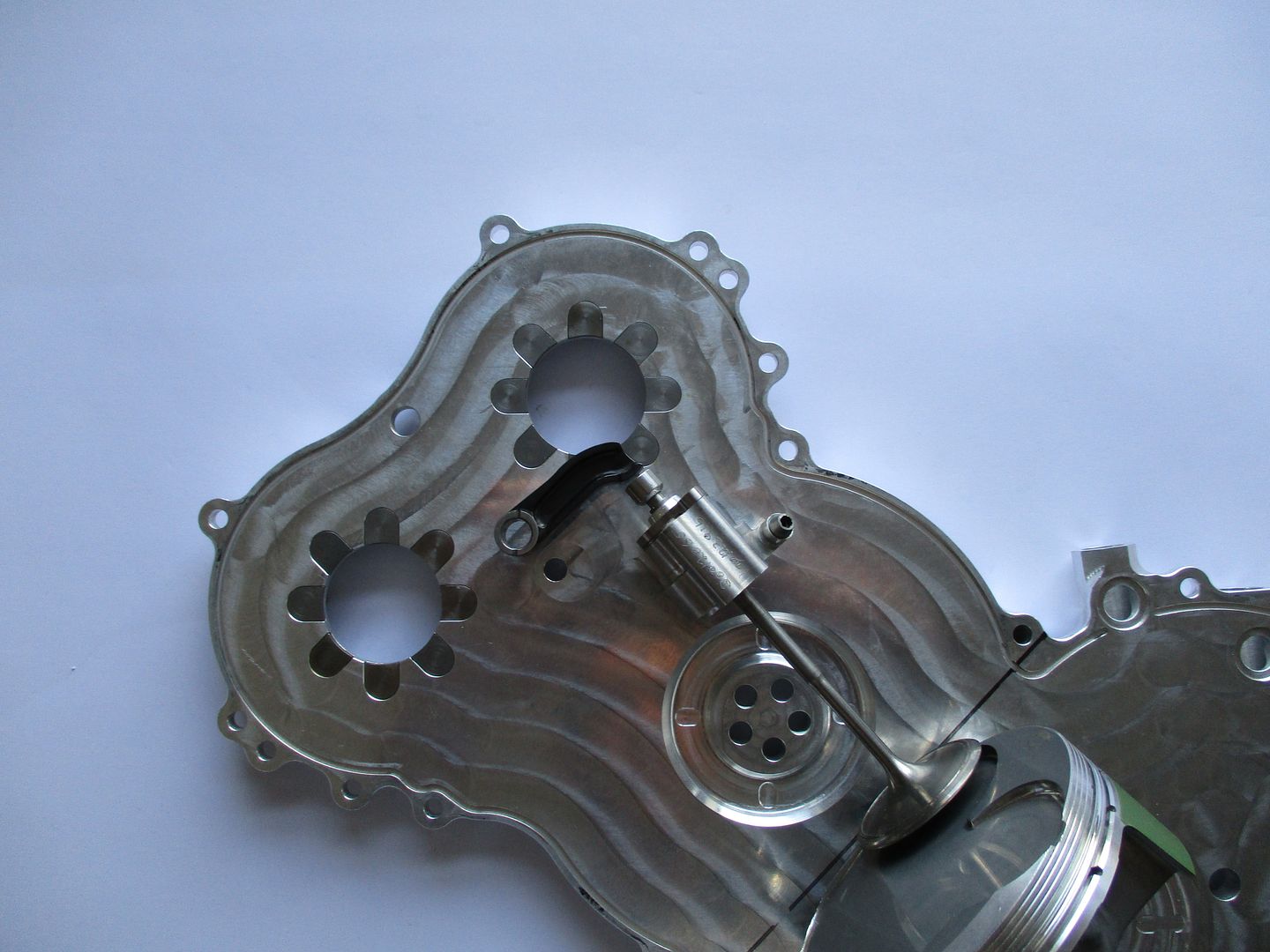
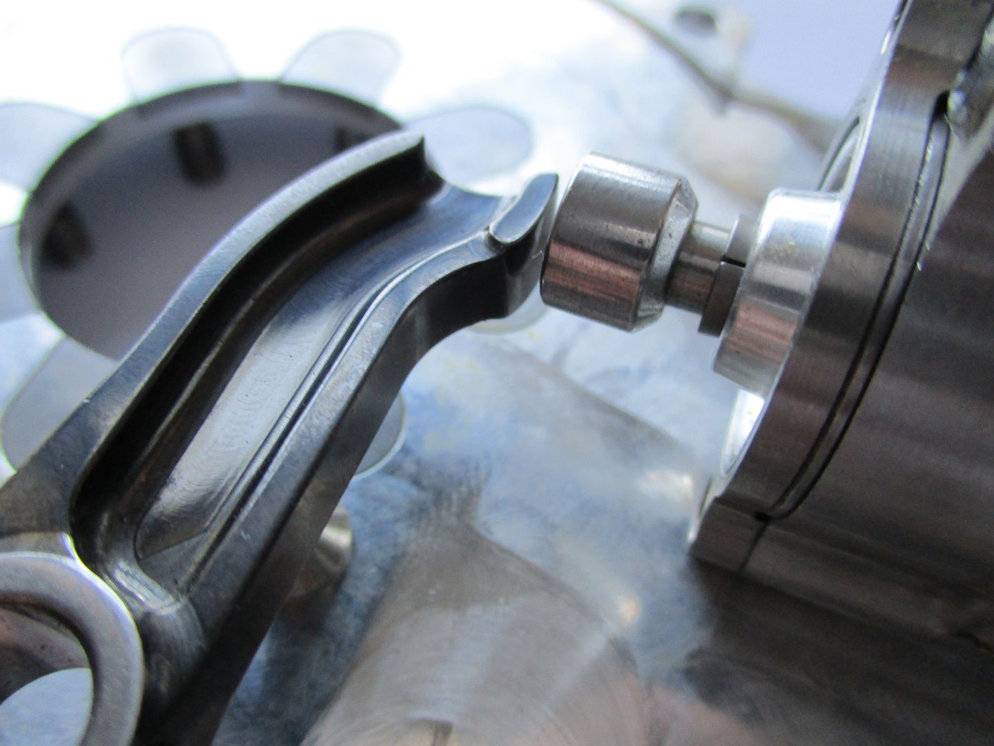
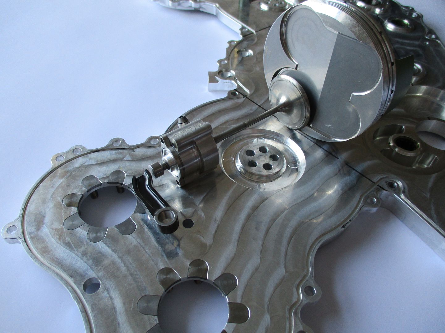
(Piston not from this engine and for illustration purposes only)
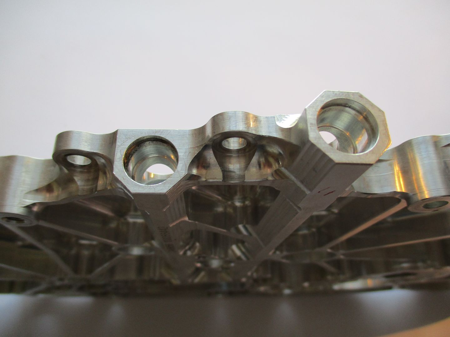
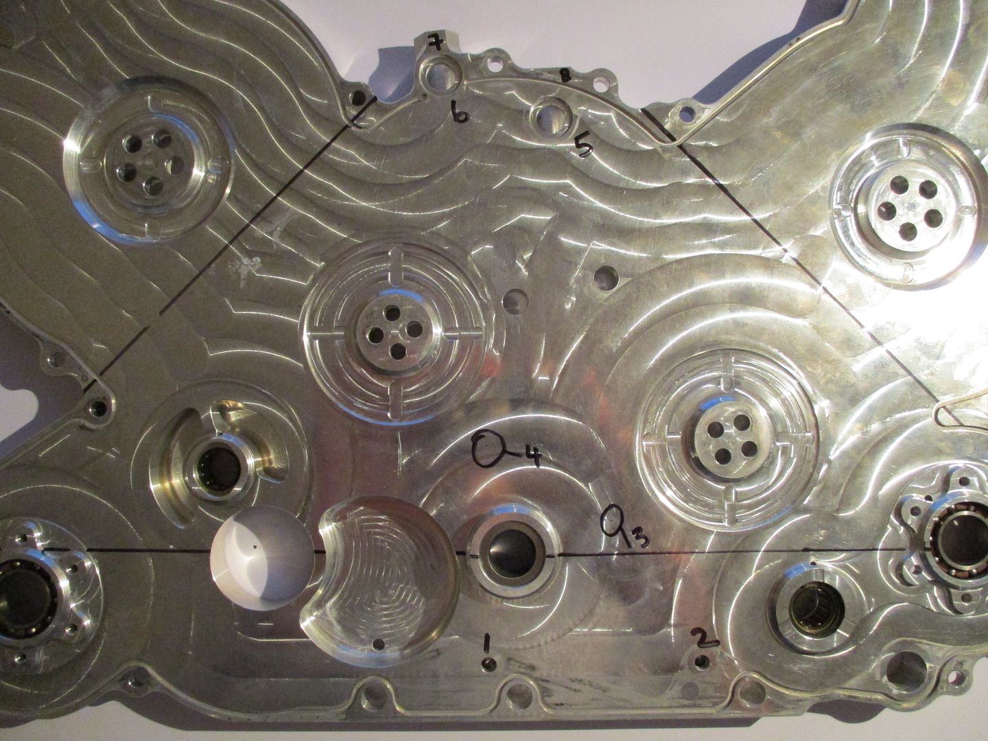
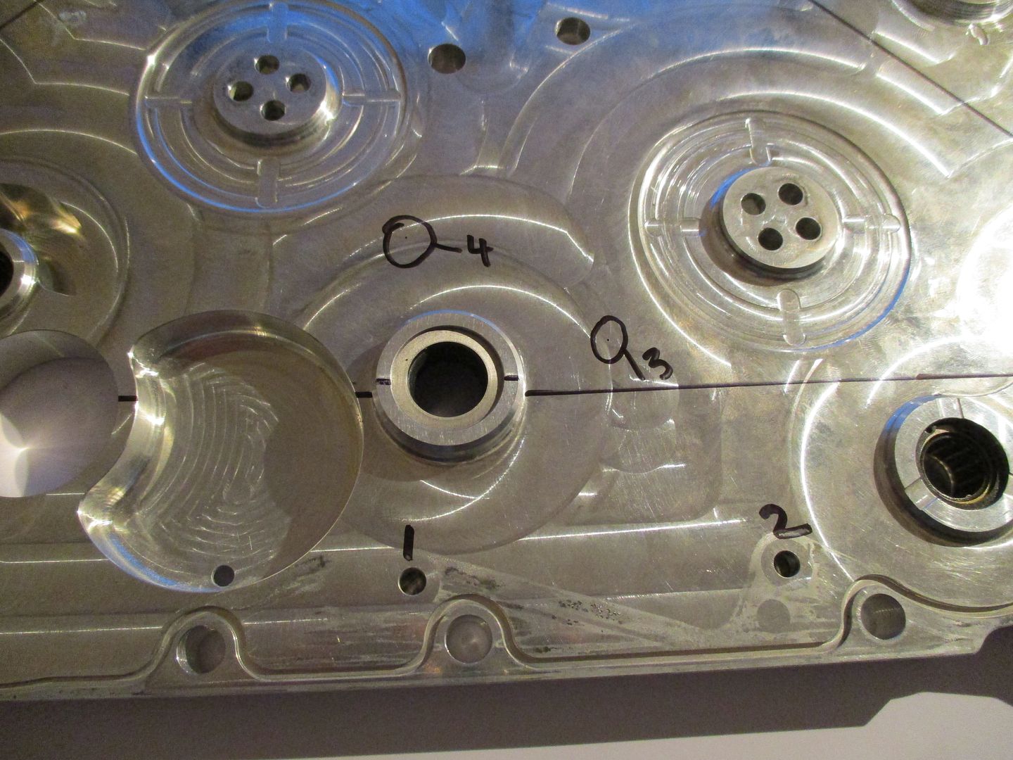
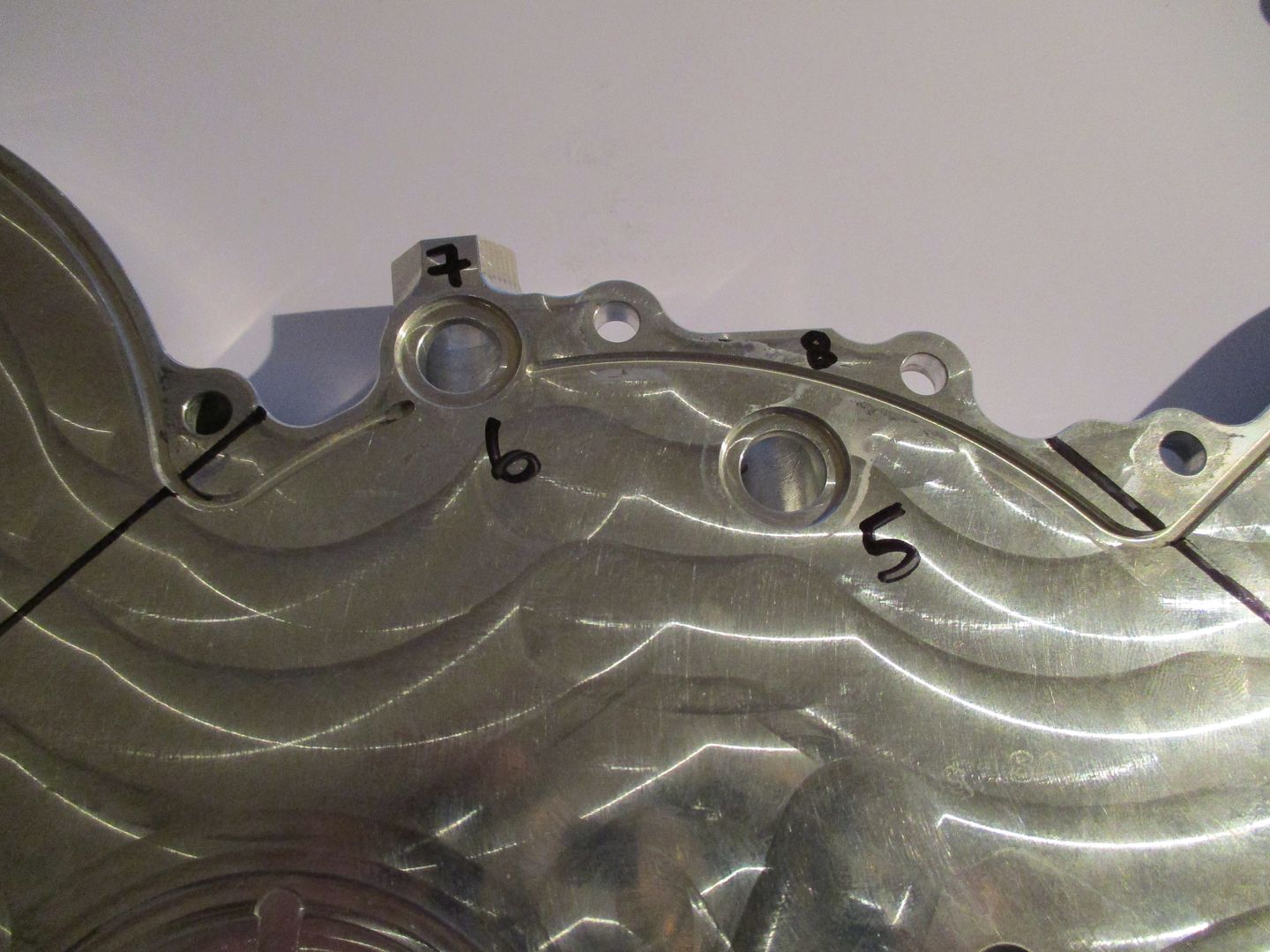
And lastly three images showing oil drillings with some numbers, where
1 = Sump Girdle Mounted Piston Squirter's
2 = Sump Girdle Mounted Piston Squirter's
3 = Timing Gear Oil Jet Orifice
4 = Timing Gear Oil Jet Orifice
5 = Into Block - Main Bearing Oil Ways
6 = Into Block - Main Bearing Oil Ways
7 = To Heads
8 = To Heads
With all of the above in mind I hope the thread and information here has helped everyone from Casual Viewers, Enthusiasts, F1 fans, Engineers, Designers, Students, and Teachers Worldwide - If you know anyone whom you think would like to see it please share this link.
All pictures are backed up and on prepay hosting so they are not going to vanish anytime soon - hopefully now there is less doubt as to what it takes to create one of the last and in my opinion the greatest ever modern day 20,000rpm Formula One Engines.
All the Best,
Brian Garvey.