F1 Throttle Actuator, a closer look

All that has to do with the power train, gearbox, clutch, fuels and lubricants, etc. Generally the mechanical side of Formula One.
Post Reply
Brian.G
334
Joined: 10 Dec 2010, 23:52
Location: Ireland
Contact:

F1 Throttle Actuator, a closer look

Post

Another part under the spot light, this time the F1 V10 Throttle Actuator.

In this thread I will be unlocking a few secrets hidden within this part - The F1 Throttle Actuator, mainly its construction, operation, and some other features.

The part below is from the Cosworth TJ V10 Engine.

In a normal road car these days the throttle butterflies are directly controlled by a small stepper/servo motor, in earlier years they were cable control. In the case of many F1 cars these methods of control have been replaced for many years by electronically controlled hydraulic actuators. Hydraulic actuation has many benefits over cable or electronic control in F1 environments for many reasons - lightness, response time, and durability being a few.

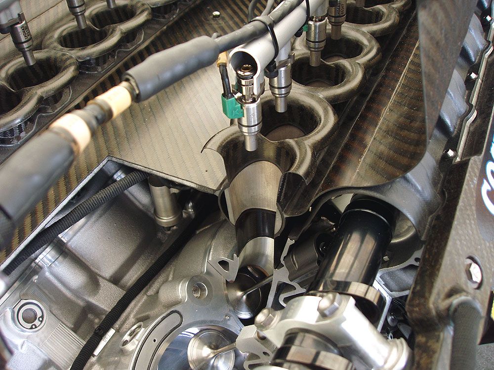
On the V10 there are two machined magnesium throttle barrels housed inside two carbon fiber tubes bonded into the carbon fiber intake superstructure. Holes in these carbon fiber pipes correspond with holes in the magnesium throttle barrels - turning the barrels 90 degrees from the idle position causes the holes in the carbon tubes and holes in the throttle barrels to line up thus giving wide open throttle.

The magnesium throttle barrels require moderate force to turn from the idle position since they are under considerable vacuum. The area in which such actuation methods would reside in is also a pretty hostile and cramped one.

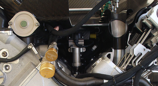
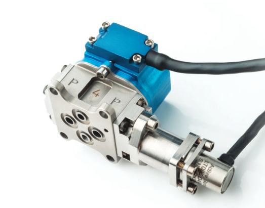
Below is the F1 Throttle Actuator in question in its fitted position, if you look closely you can just about see it lying over the valley area of the engine block and under the main intake superstructure, its flow and return caps exiting also and capped off,

Image

Image

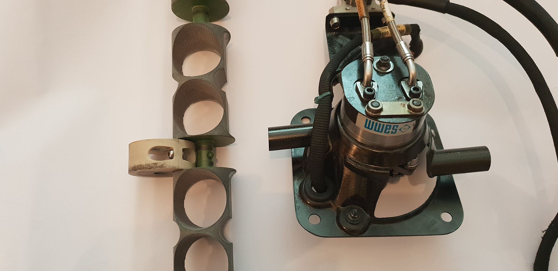
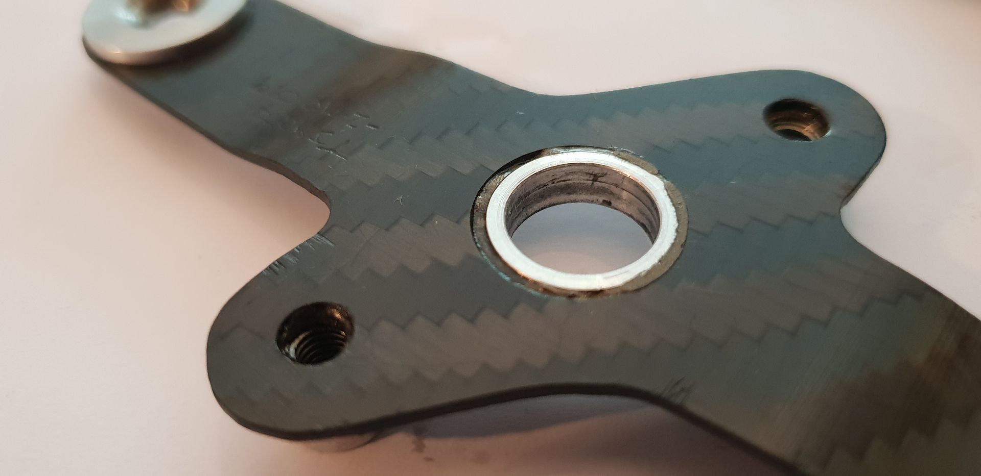
The Throttle Actuator removed below - two linkages not pictured exit from the actuator bell crank and attach to crank arms on the magnesium throttle barrel central bushings - the bushings made from PEEK.

Image

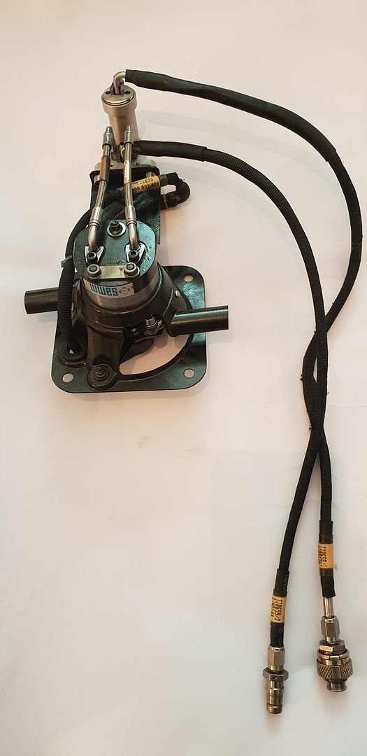
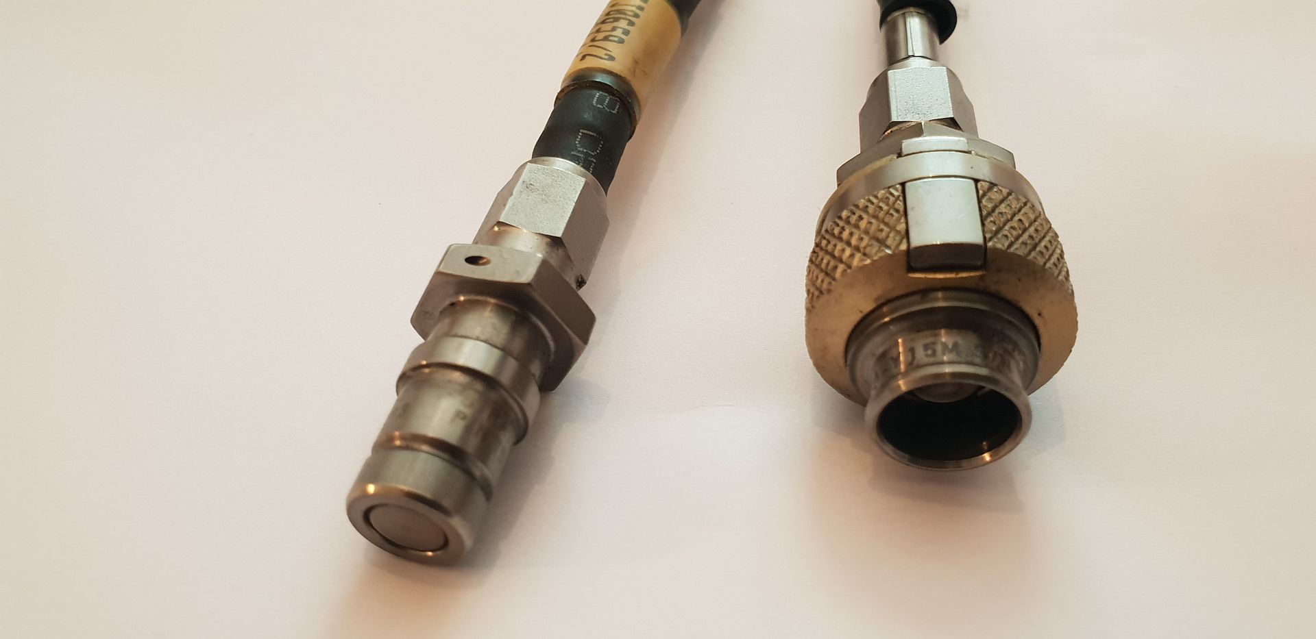
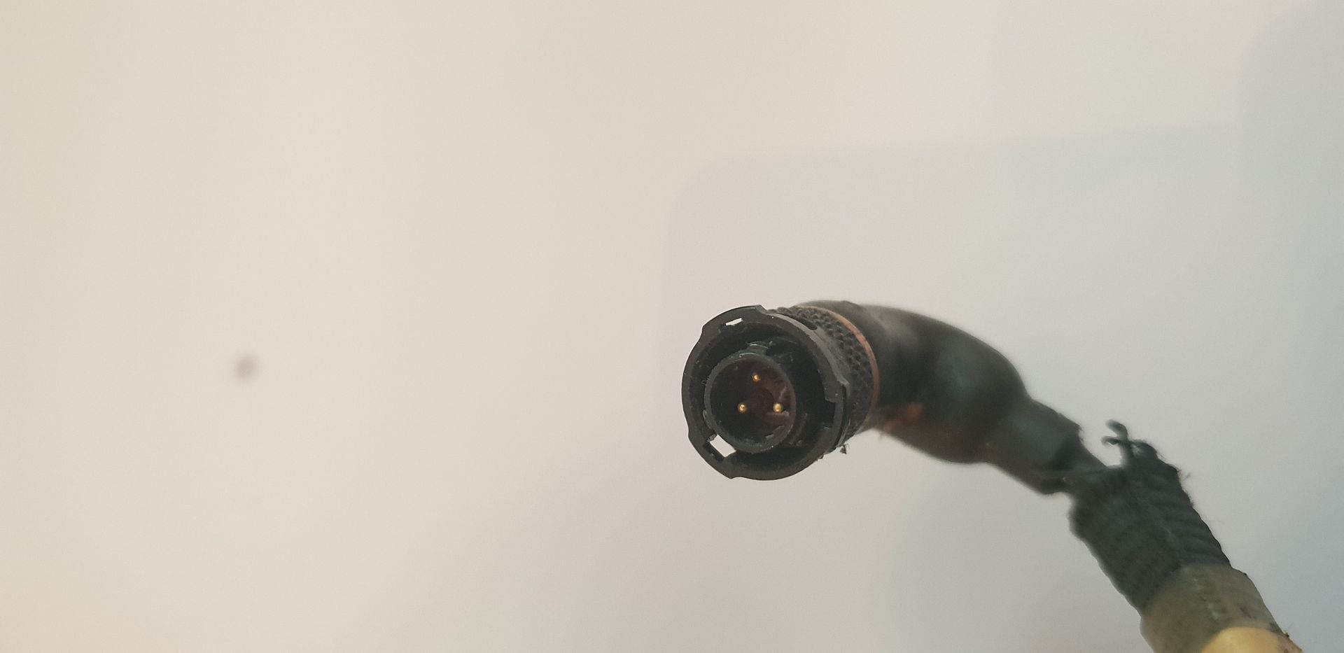
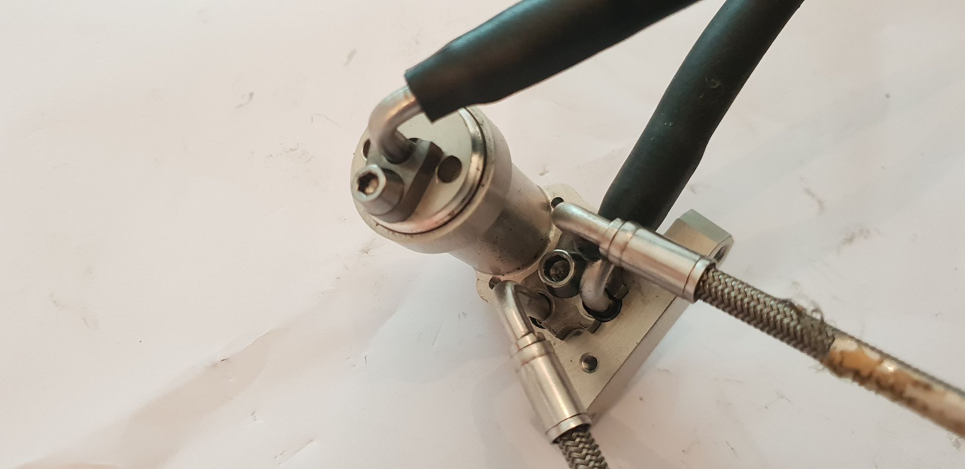
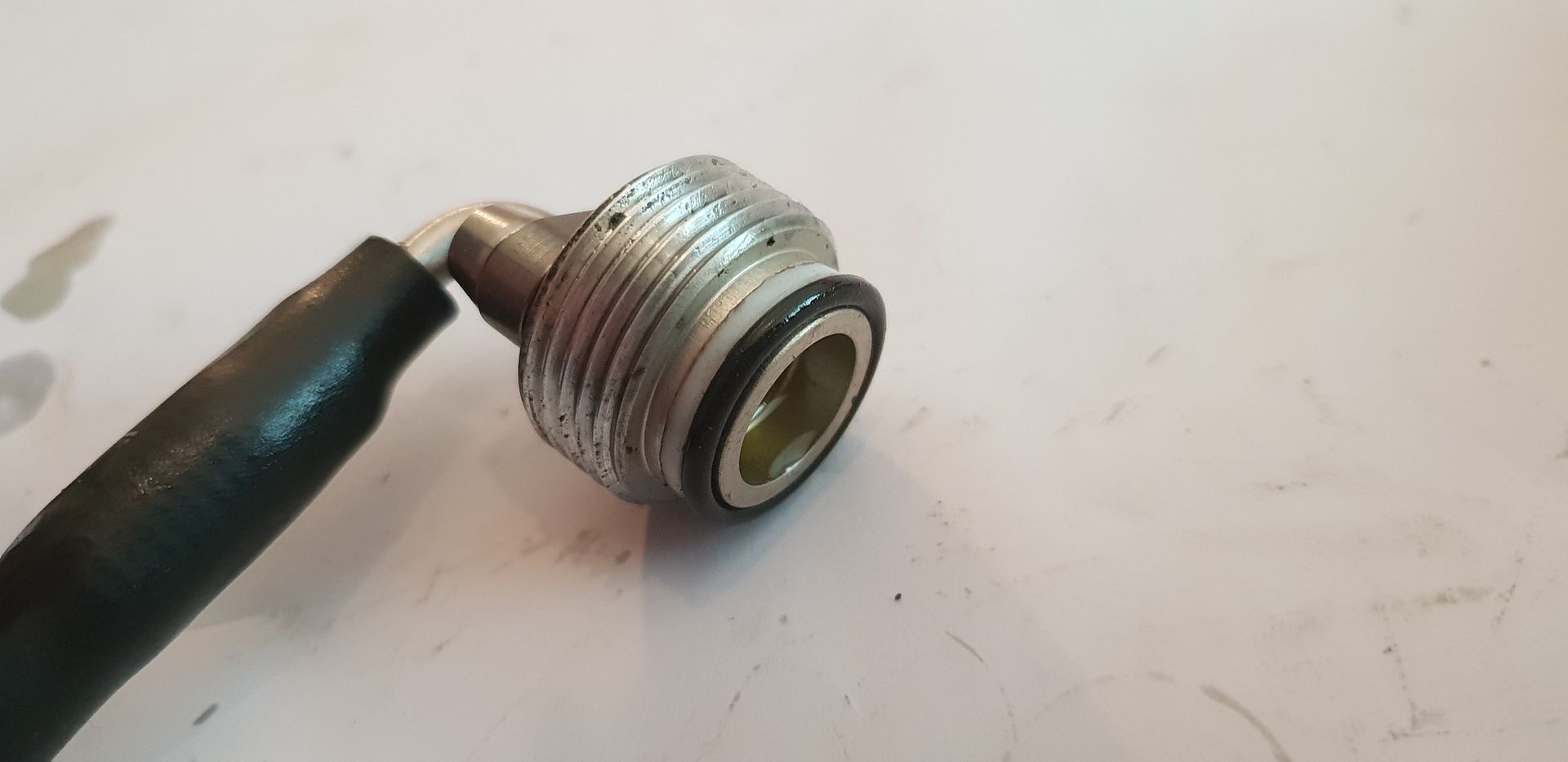
The dry break connections,

Image

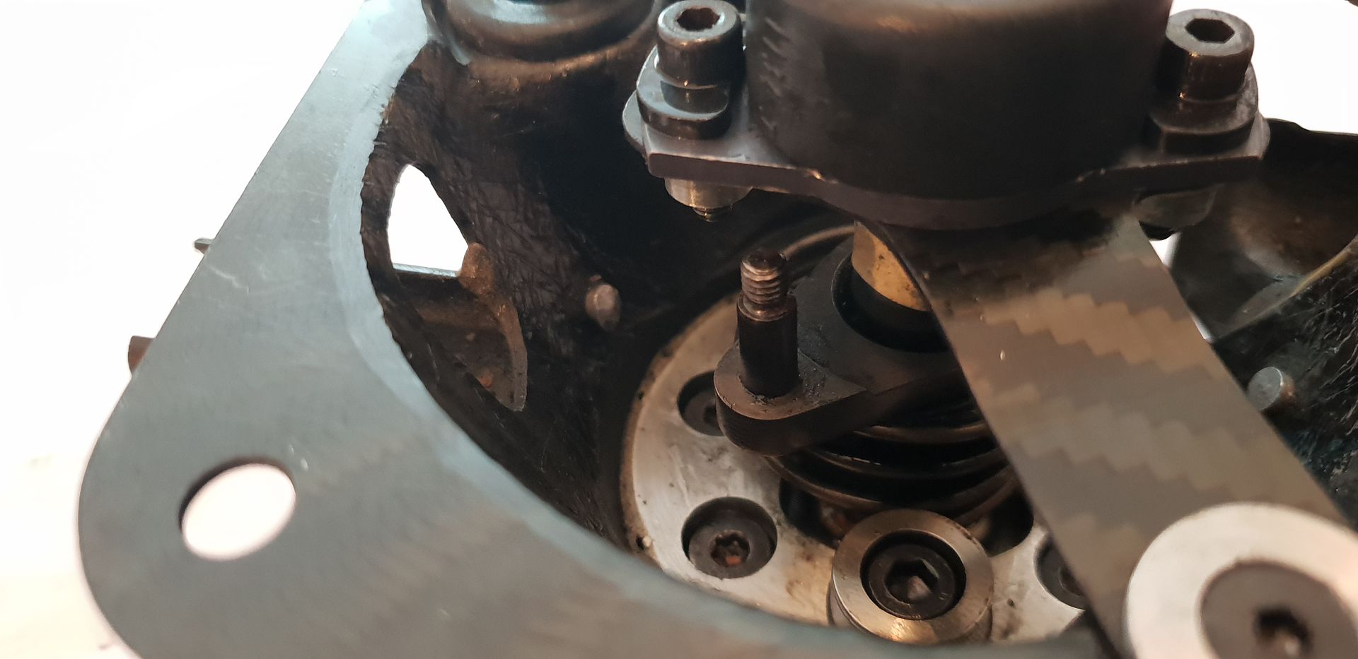
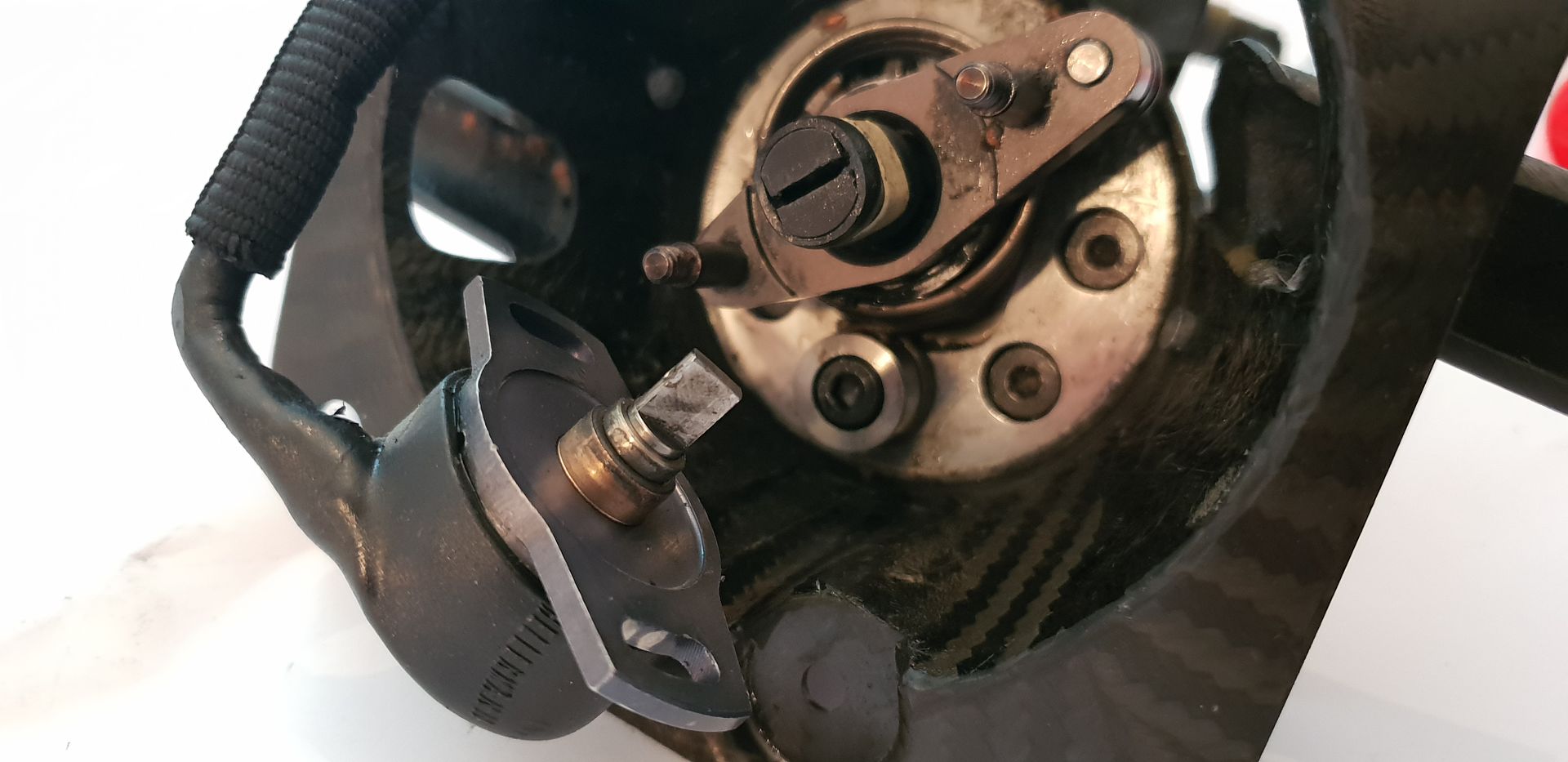
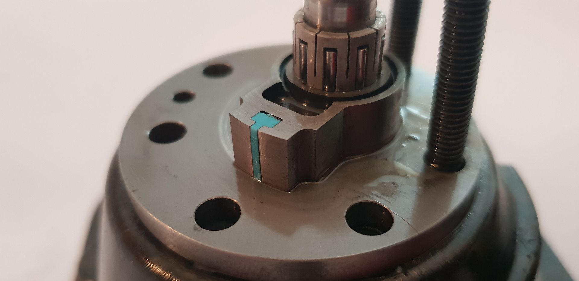
The left hand throttle barrel in its approximate position showing the central PEEK crank bushing - you can just make out the small indexing pin on the throttle barrel axis to provide positive angular location for the PEEK bushing,

Image

Turned over, you can see the rotary encoder for positioning monitoring,

Image

Notice too the upstands on the bell crank for connecting the link bars out to the barrel bushings,

Image

Image

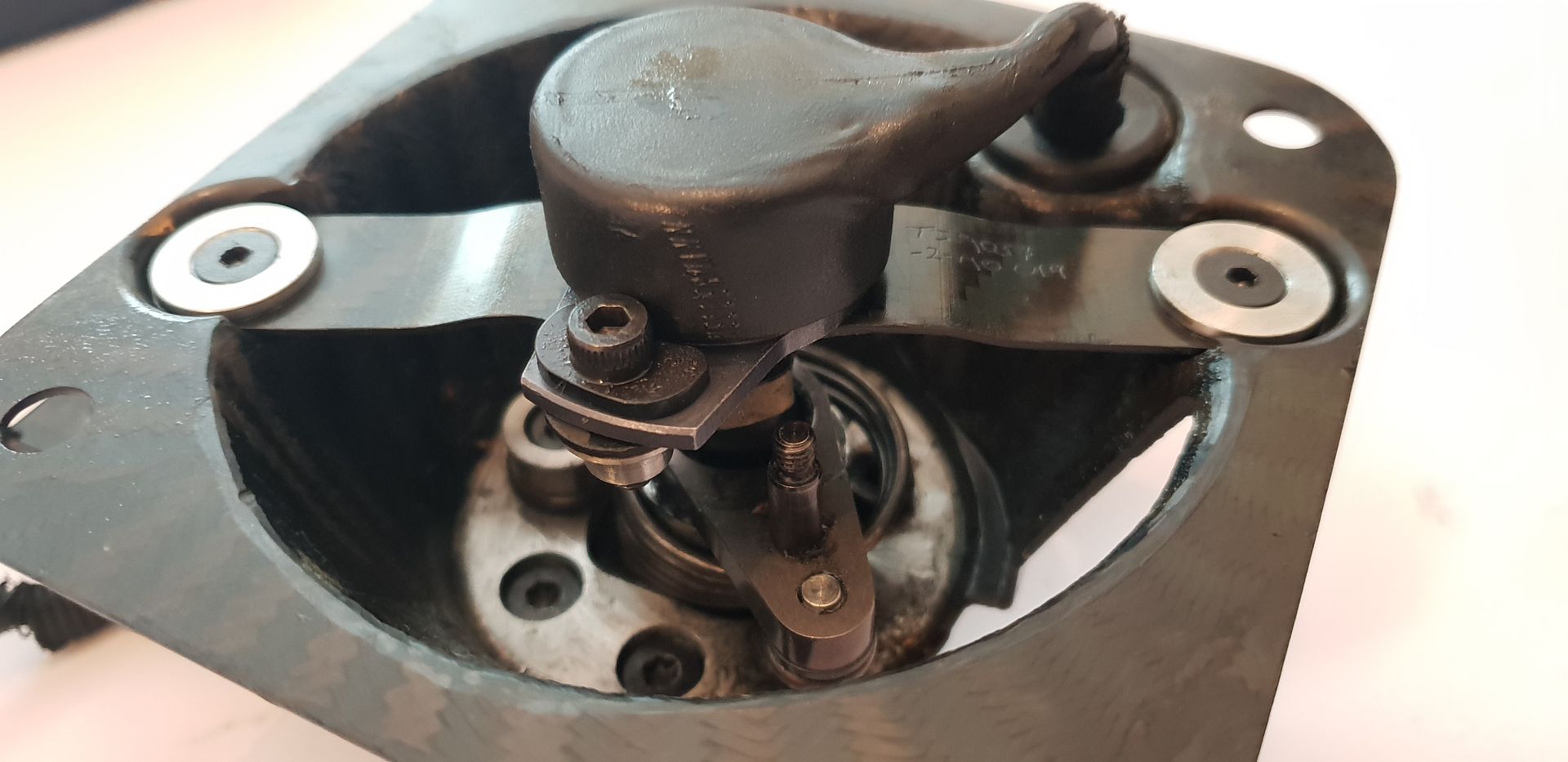
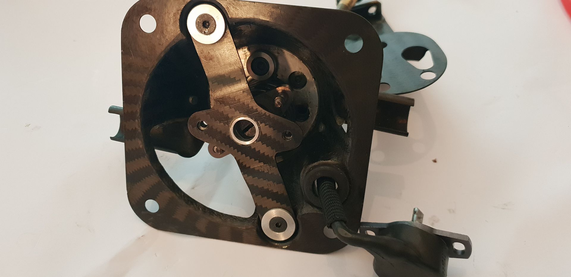
Removing the encoder uncovers the bracket and coupler which it mounts to,

Image

The encoder cable has three conductors,

Image

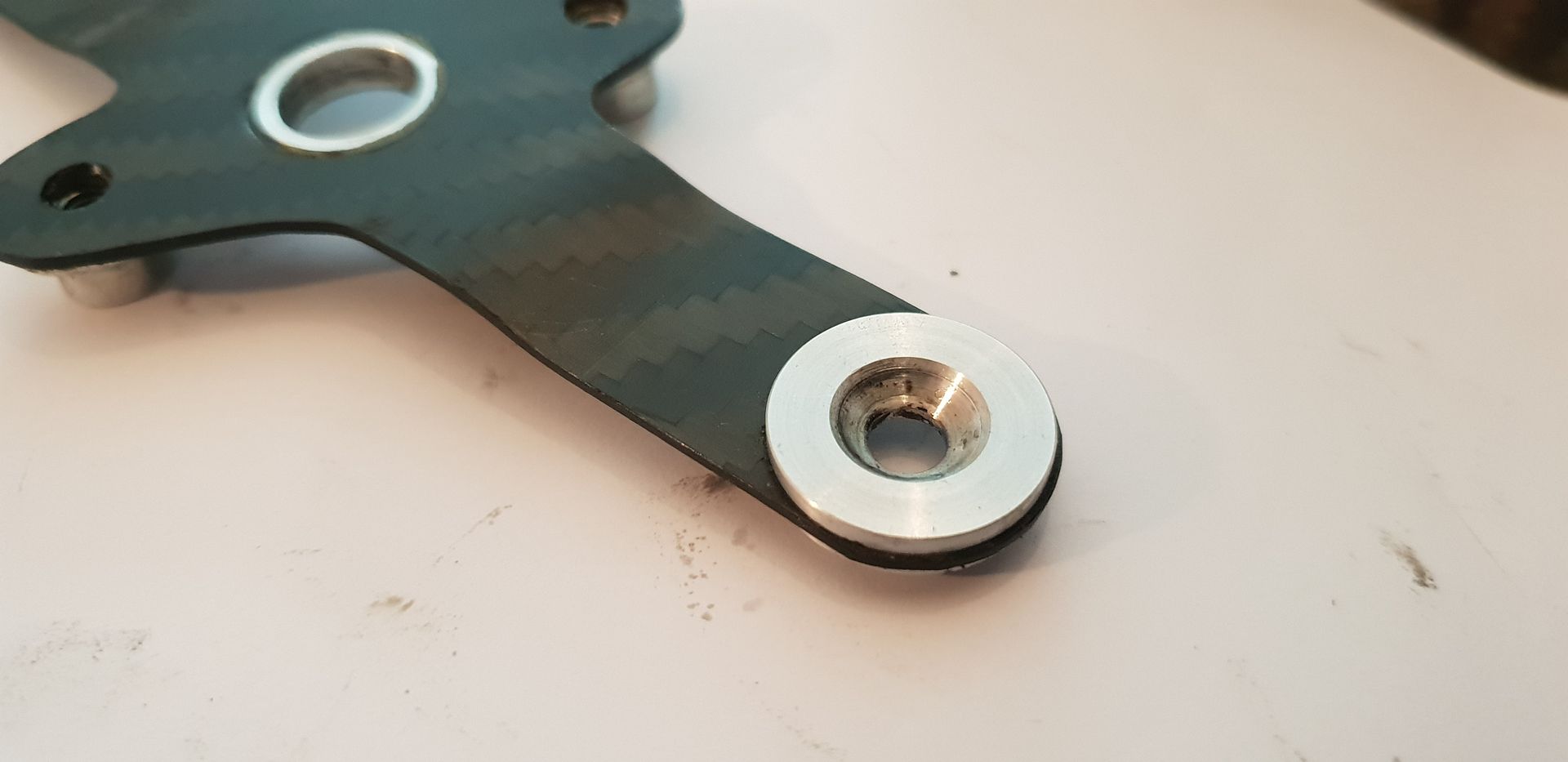
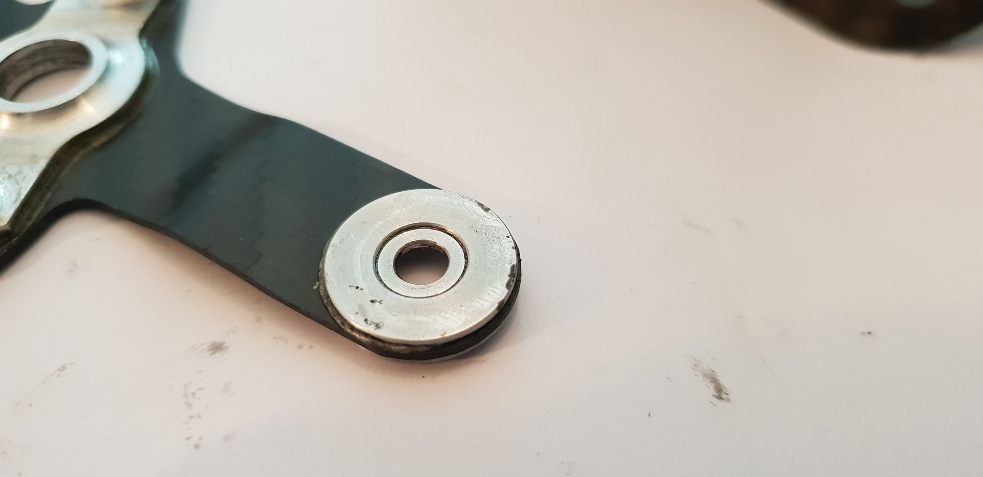
Encoder mount piece removed, fastener load spreading inserts are titanium and the outer ones two piece and bonded from both sides, threaded holes in titanium are tapped to M5 and heli-coiled down to M4 which is standard practice in titanium and aluminium as the fasteners can cold weld and gall on removal otherwise. Heli-coiling is also used on smaller hole callouts for deep threads and is an often overlooked solution if tap breakage is an issue. An M3 threaded hole callout is instead tapped to M4 and Heli-coiled back down to M3 - the M4 tap being superior in terms of chip evacuation and strength.

Image

Image

Image

Image

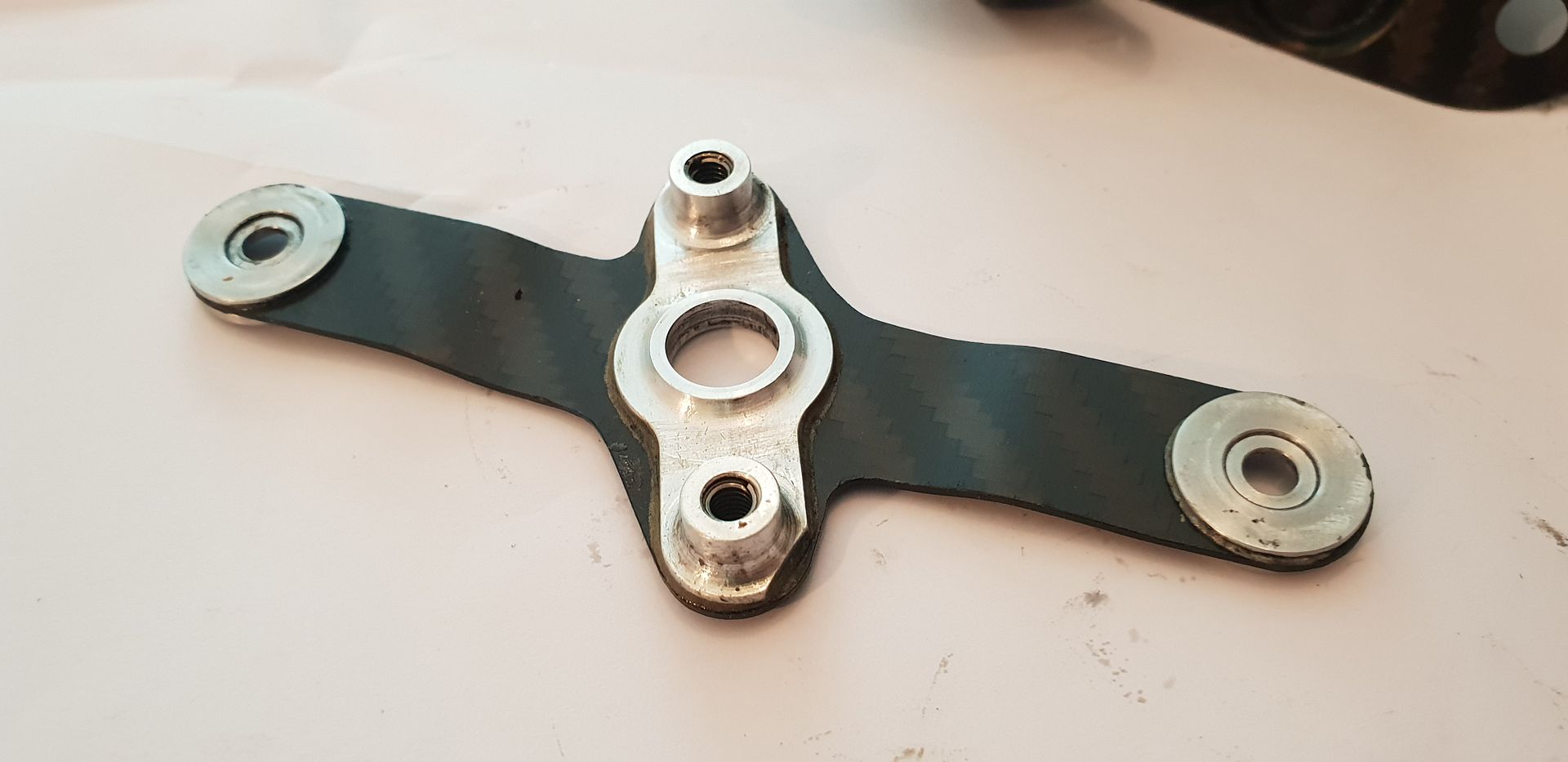
The Encoder shaft and coupling to actuator,

Image

The coupling is of novel design and comprises of two pieces of Nylon encased in adhesive heat-shrink,

Image

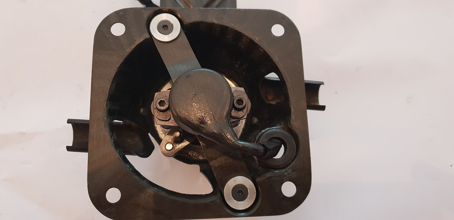
The actuator bell-crank and linkage upstands,

Image

All fasteners holding the actuator body together feature Schnorr anti vibration washers. Schnorr washers are the most expensive washers in terms of locking washers and deemed to be the best locking solution there is. From memory an M10 Schnorr washer is approximately 3euro - so not cheap. Bolts are low profile heads too for weight savings,

Image

The return spring locates on one of the bolts holding actuator to carbon fiber basket,

Image

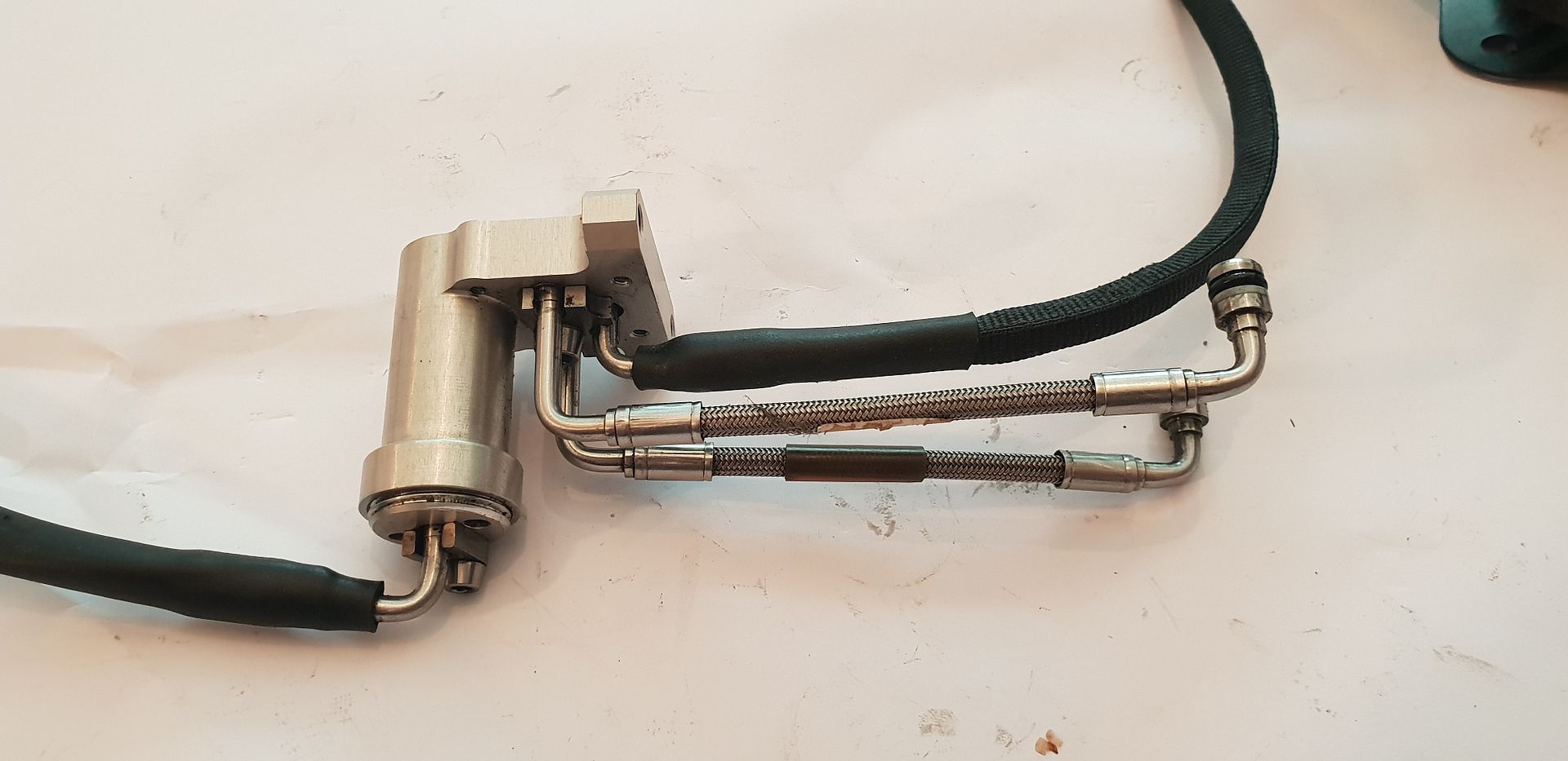
Flipping the assembly over and removing the control hoses and spool valve manifold assembly,

Image

Image

Image

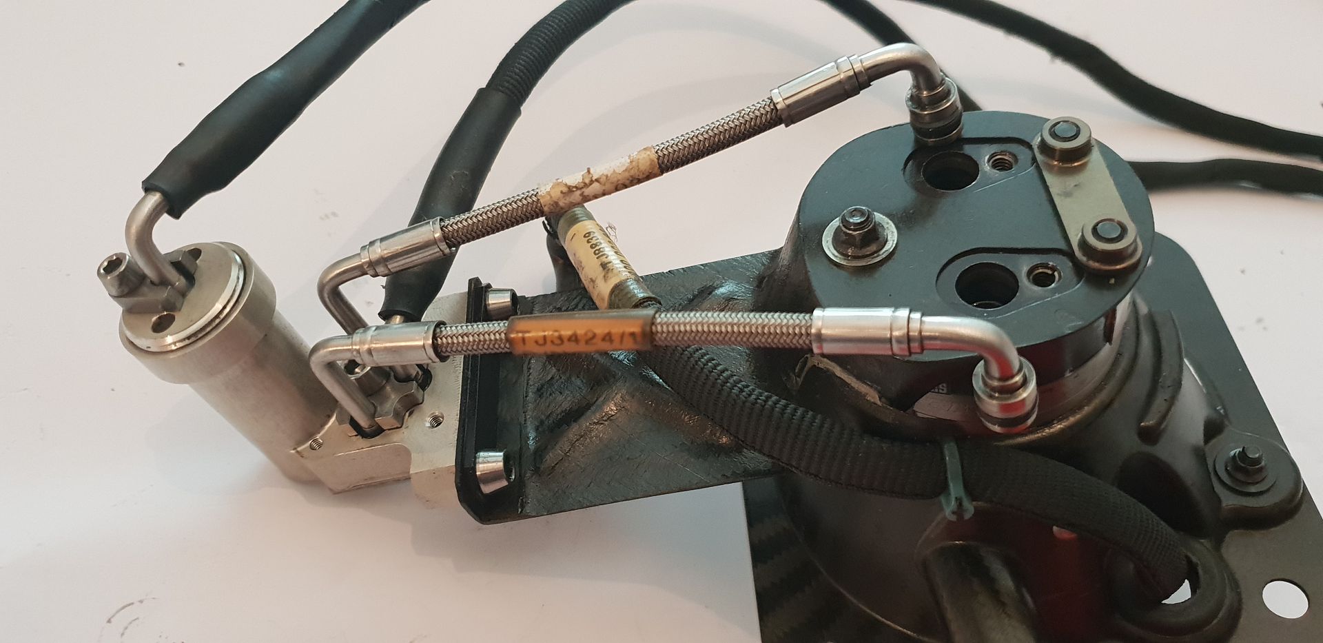
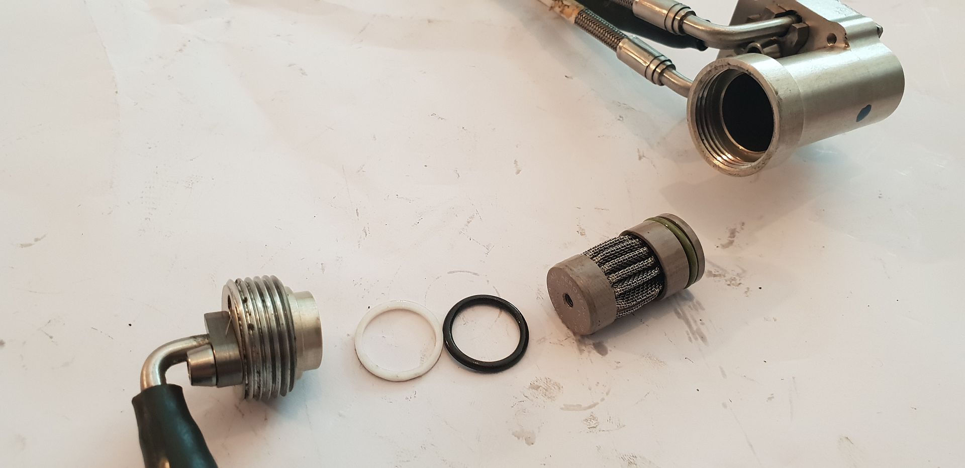
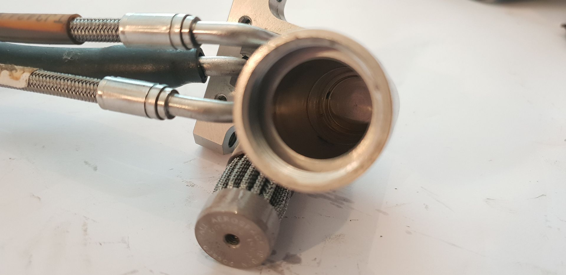
The electronic spool valve manifold assembly, supply filter, and actuator hoses below, supply hose on left, braided actuator hoses in center and return hose on right,

Image

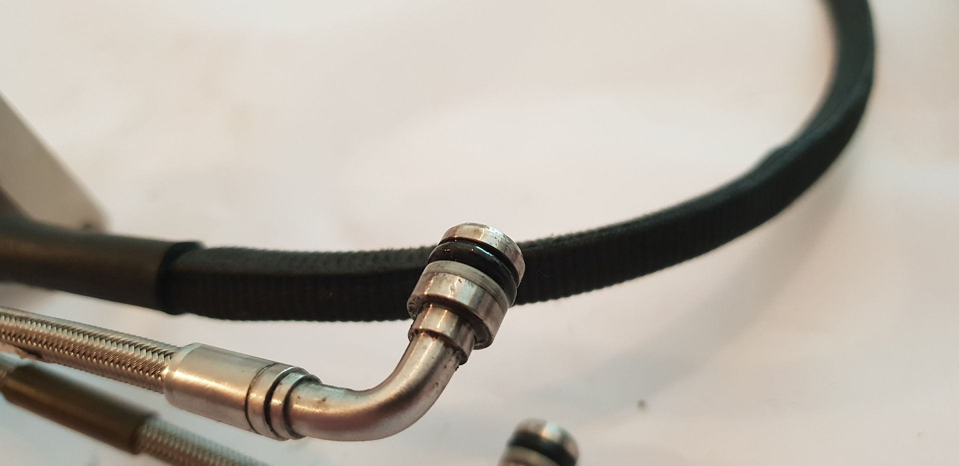
The end detail of the braided hoses which locate into actuator rear cap,

Image

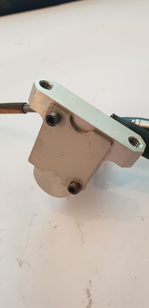
The filter housing and main manifold body,

Image

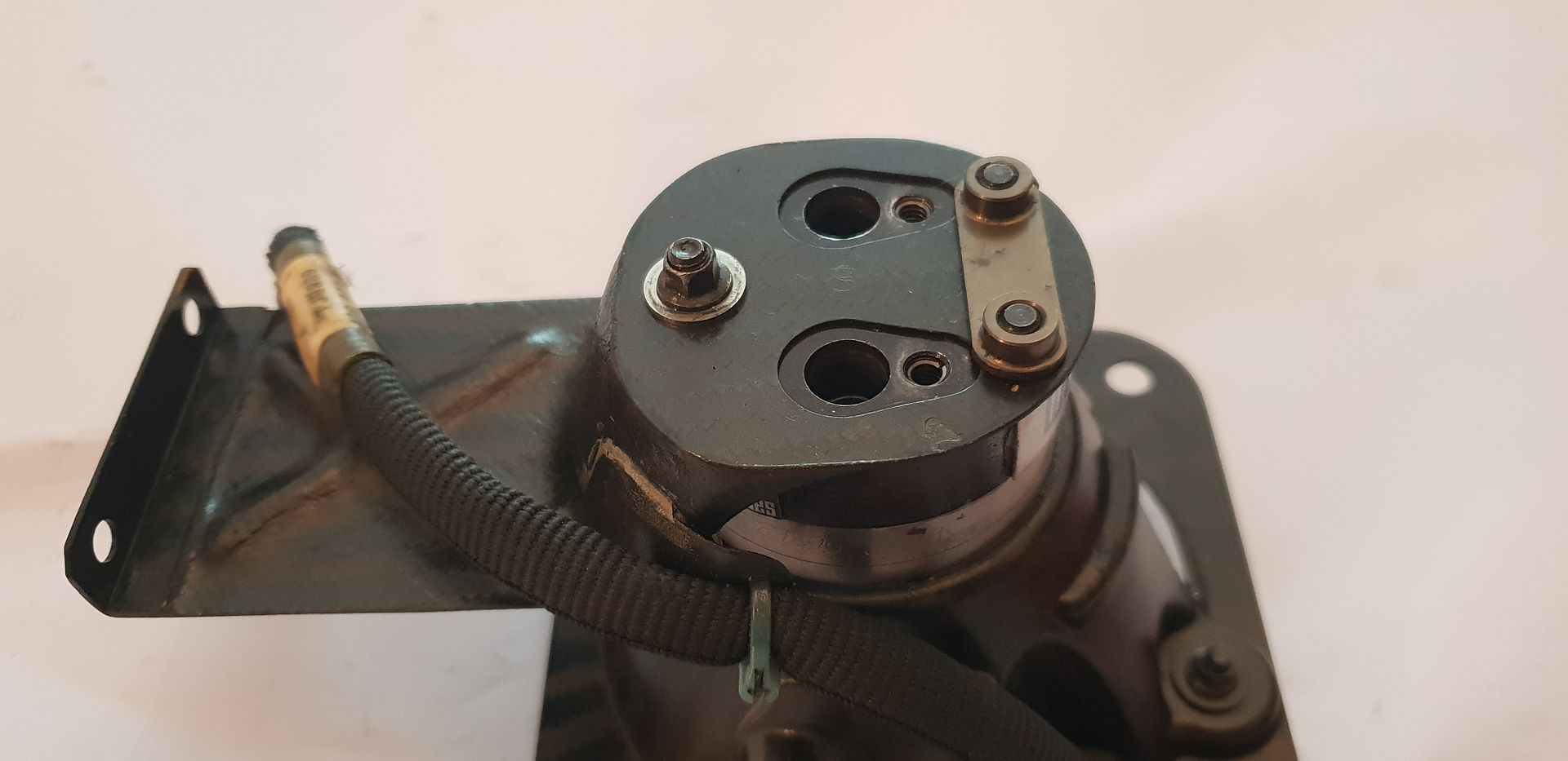
A protective cover plate blocks off the small manifold oil drillings while in transit - the electronic spool valve mounts in its place at time of engine building,

Image

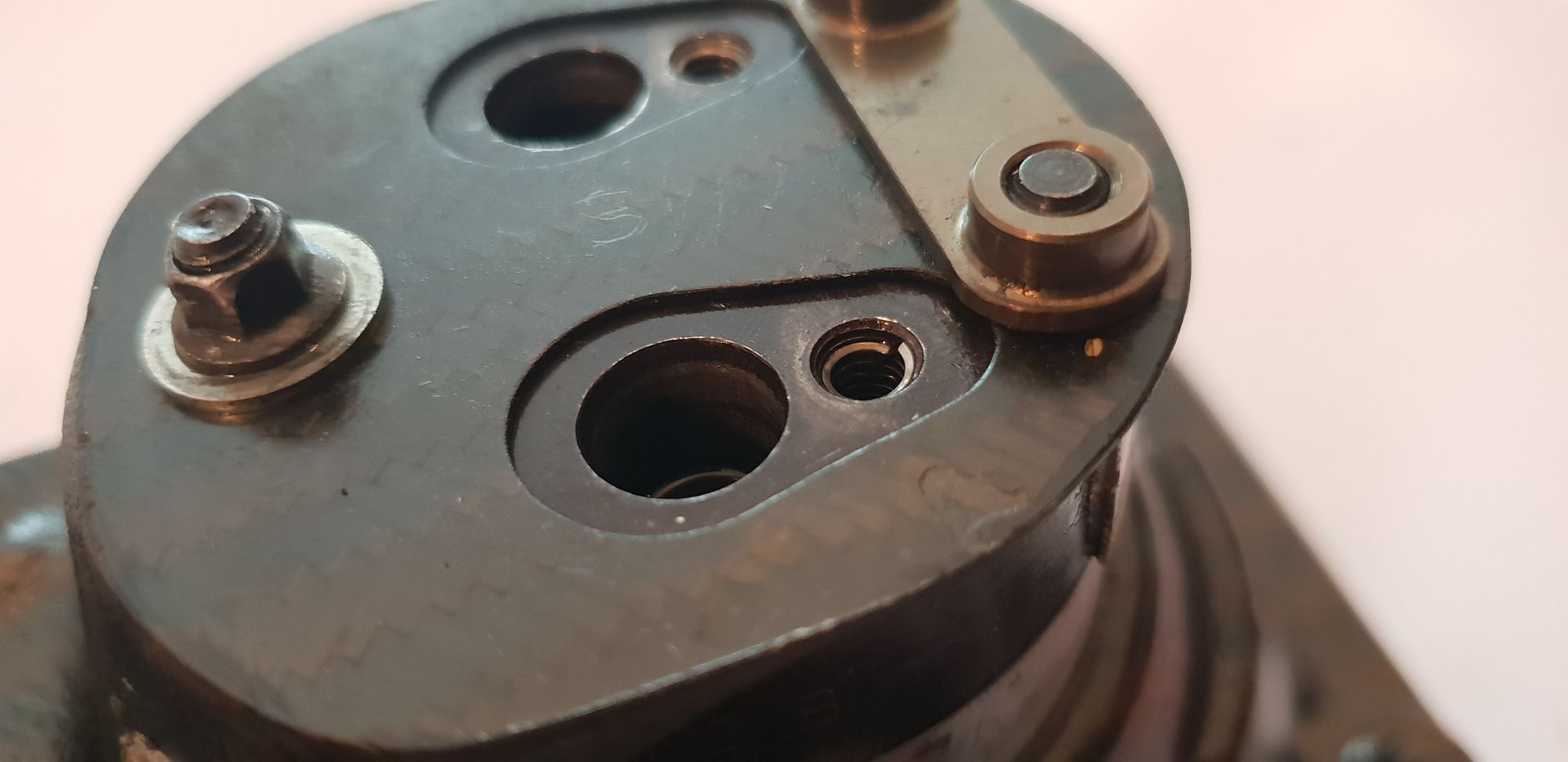
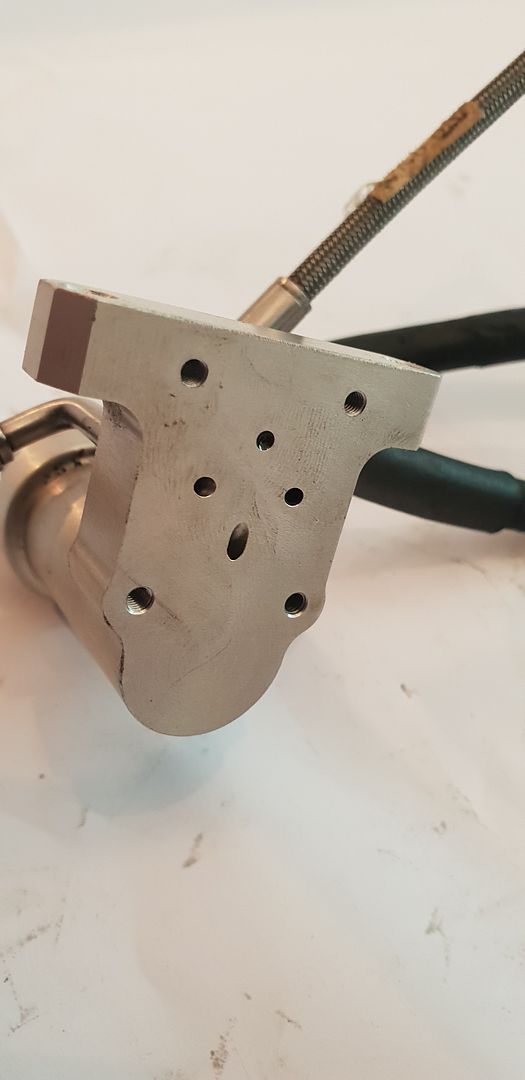
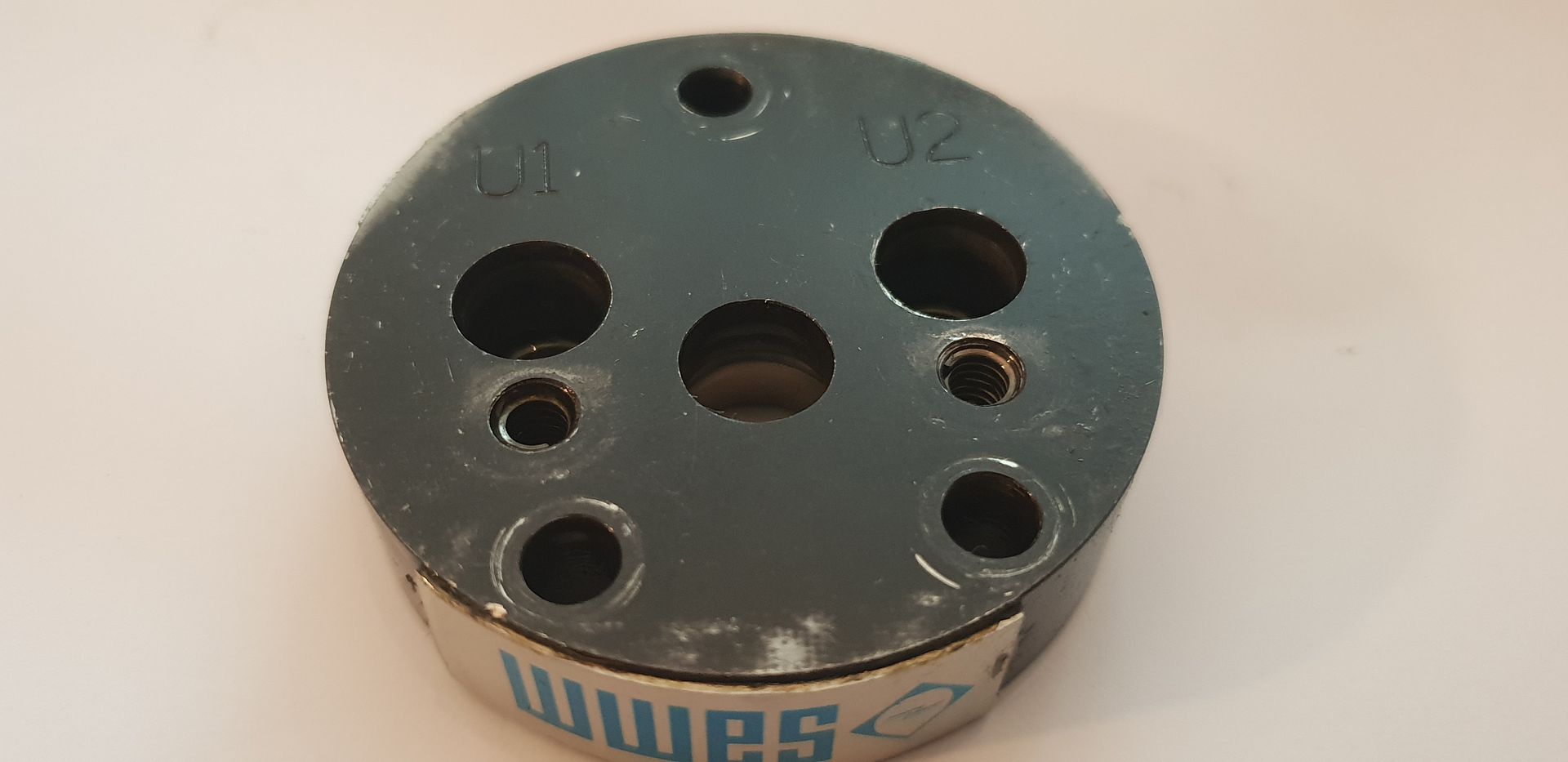
The blanker plate removed and the drillings exposed - flow from base of filter chamber on the bottom, left/right drillings to actuator and return on top,

Image

The spool valve which mounts to the manifold shown below - it features dual coils with spool position feedback. Its coils are simultaneously controlled via pulse width modulation from the ECU driver board. If you think of pulse width modulation like bouncing a tennis ball in the air with a tennis racket to a given height each time it is a similar process- the harder you hit the ball the higher you can keep ball each time. The spool valve coils operate under the same principle - the longer the electronic pulse width each time the further over it moves the spool valve, in turn allowing a greater volume of oil to flow to the actuator vane cavity- turning it more. Some valves however are also analogue - higher voltage - spool moves across more...no PWM signal required and akin to holding the tennis ball in air at various heights instead of constant bouncing!

Image

A quick look inside the integrated manifold filter housing,

Image

Image

Image

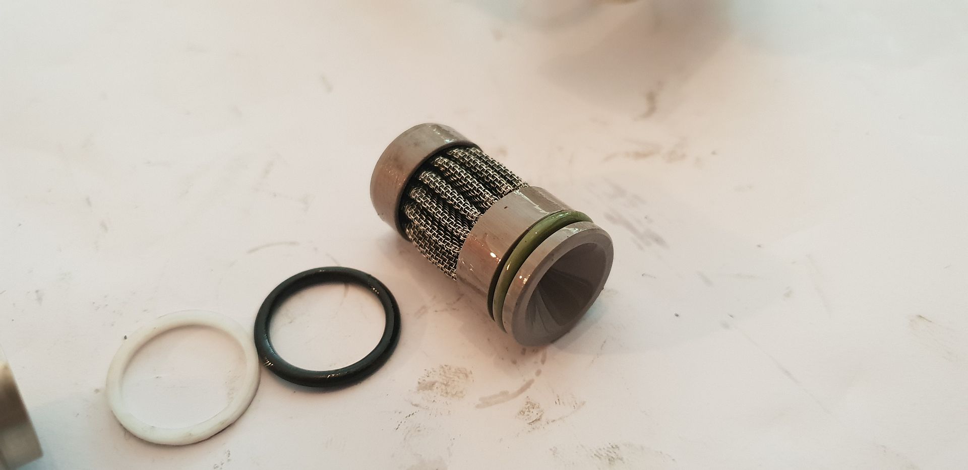
You can just make out the outlet port inside,

Image


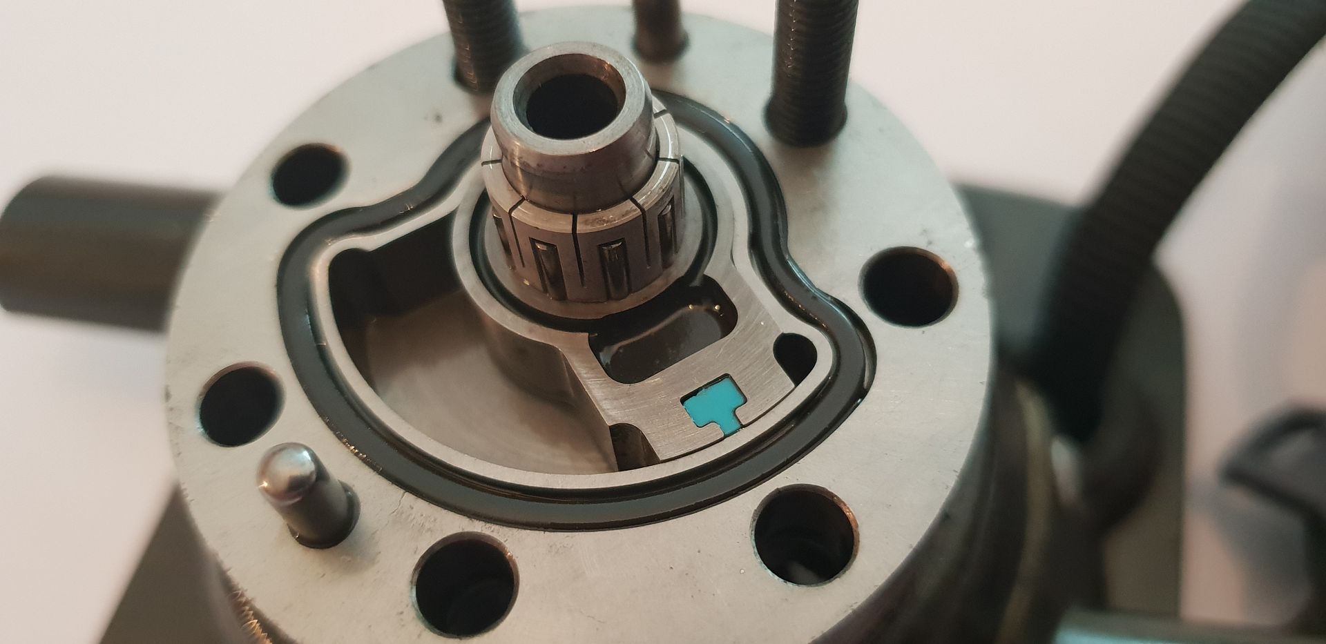
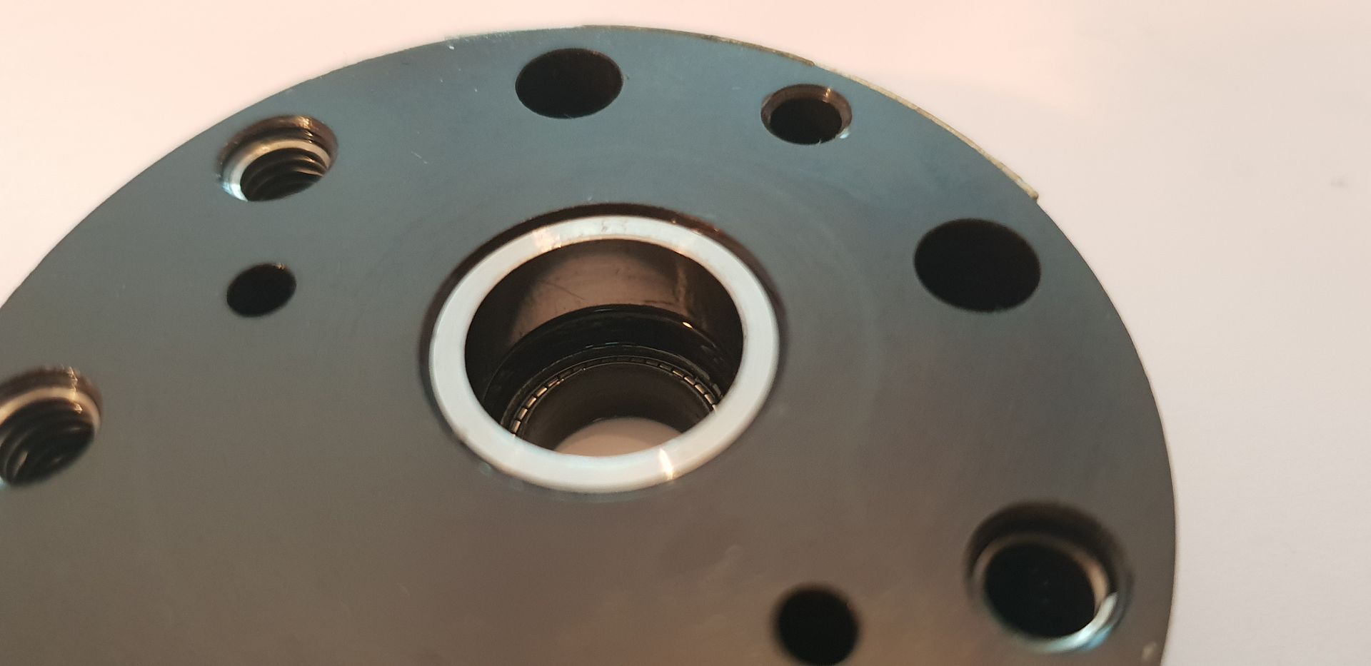
Returning back to the actuator and with the rear cover off you can see its method of operation - the actuator is of the ''Rotary Vane'' type and common in these types of applications. As you can see below, the cap has two ports - each port lies over the small space beside the vane - modulated fluid pushes the vane to the chosen angular position,

Image

Image

Image

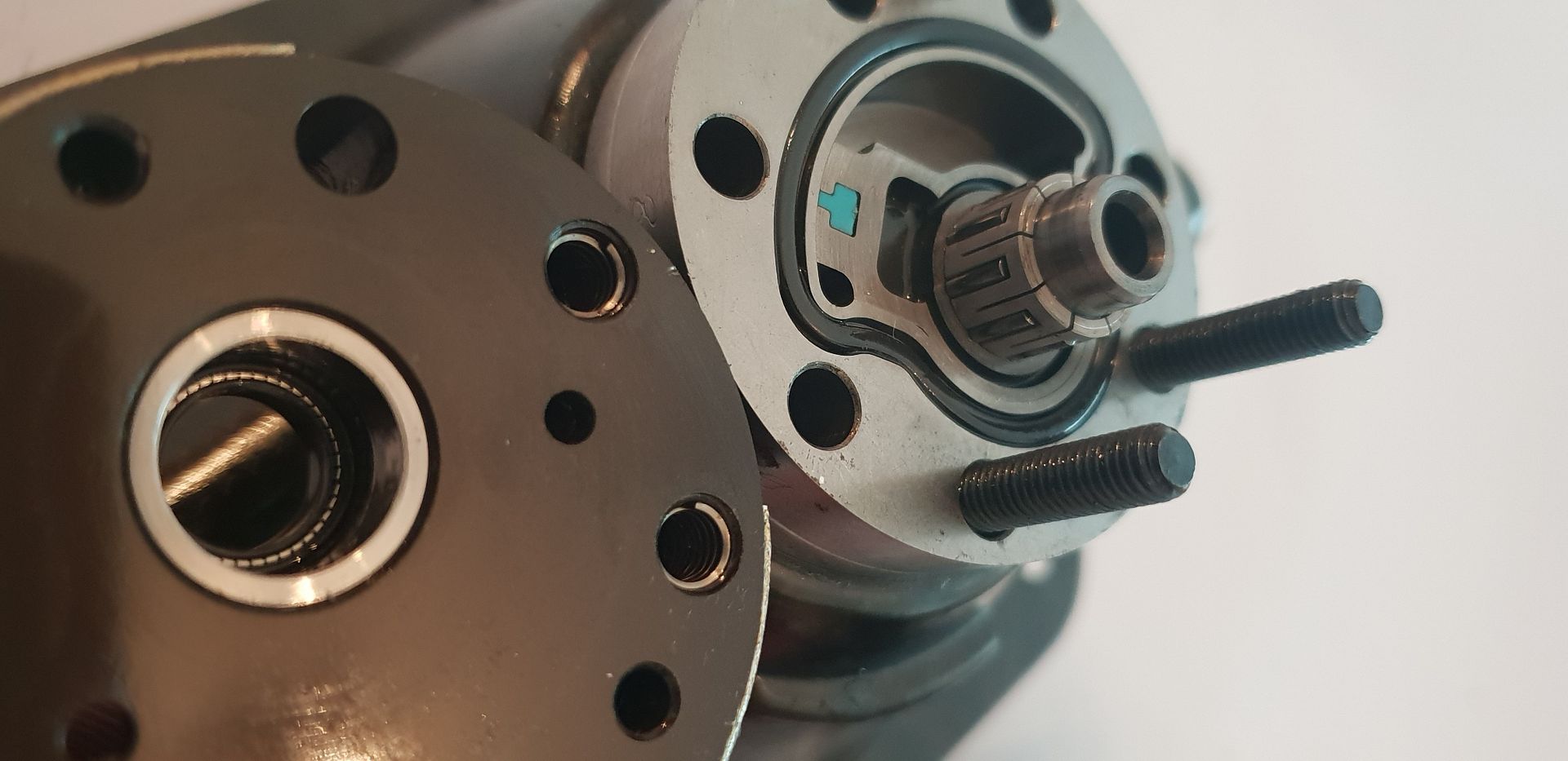
The spindle sits in a steel bushing pressed into the aluminium cap, shaft seal also visible,

Image

With the mid section removed you can see markings caused by the vane vibrating when in the idle position - the engines are designed with the most resonance present at idle since they dont spend much time there,

Image

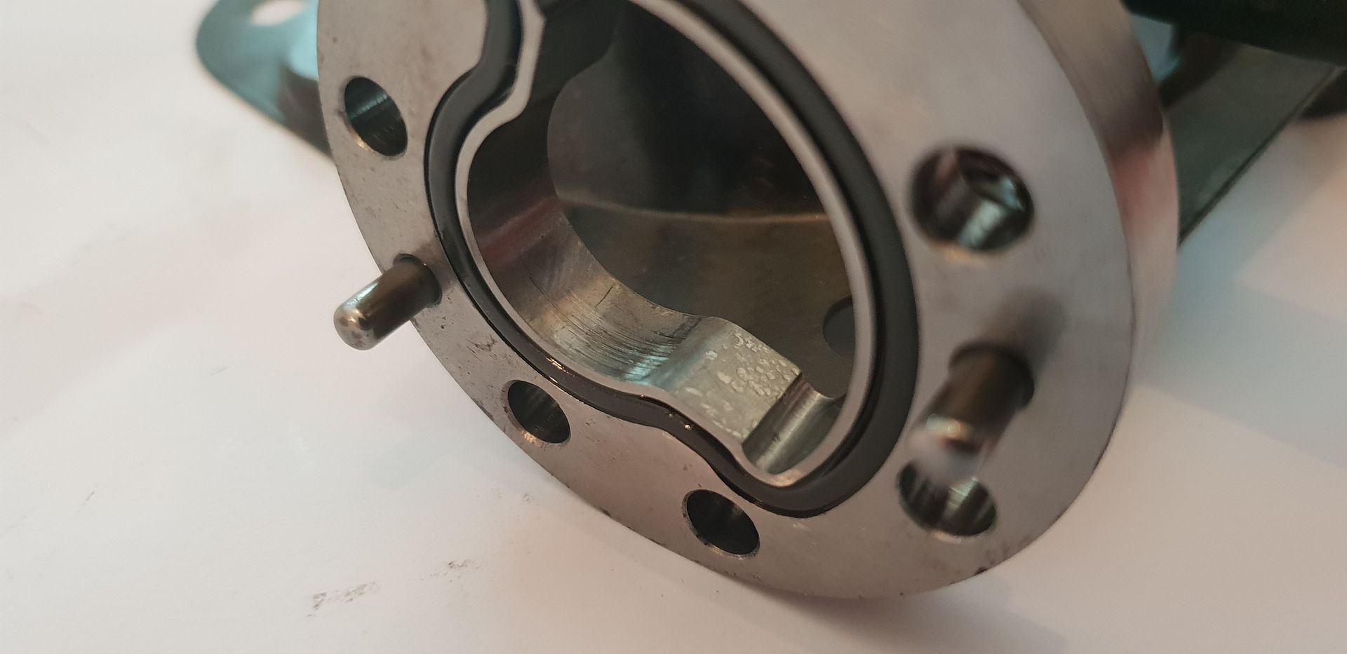
And the wiper seal detail,

Image

So thats pretty much it in terms of what the F1 Throttle Actuator looks like externally and internally - neat piece of kit and pretty important really...

Until next time,

Brian,
If you think you cant, you wont, If you think you can, you will

Maritimer
19
Joined: 06 Sep 2017, 21:45
Location: Canada

Re: F1 Throttle Actuator, a closer look

Post

How much hand finishing goes into these parts? I assume tapping and deburring at least, dont trust machines to tap anything at my work.

Brian.G
334
Joined: 10 Dec 2010, 23:52
Location: Ireland
Contact:

Re: F1 Throttle Actuator, a closer look

Post

Maritimer wrote:
08 Mar 2019, 02:37
How much hand finishing goes into these parts? I assume tapping and deburring at least, dont trust machines to tap anything at my work.
From looking at them...I would say they are rigid tapped on the cncs...and chamfered/de-burred on them too with XEBEC brushes or similar, definitely no signs of a stray operator de-burr hand tool anyway...

Brian,
If you think you cant, you wont, If you think you can, you will

User avatar
Big Tea
99
Joined: 24 Dec 2017, 20:57

Re: F1 Throttle Actuator, a closer look

Post

I an somewhat surprised at the inclusion of a filter in line. I would assume any impurities would have been removed from the fuel before it was put in the car. Then again, I am thinking along the lines of the filter slowing the flow, are there other reasons, such as smoothing, where it is useful?
When arguing with a fool, be sure the other person is not doing the same thing.

Brian.G
334
Joined: 10 Dec 2010, 23:52
Location: Ireland
Contact:

Re: F1 Throttle Actuator, a closer look

Post

Big Tea wrote:
08 Mar 2019, 17:14
I an somewhat surprised at the inclusion of a filter in line. I would assume any impurities would have been removed from the fuel before it was put in the car. Then again, I am thinking along the lines of the filter slowing the flow, are there other reasons, such as smoothing, where it is useful?
Its not uncommon to have a secondary filter upstream of a dry break connection as the can pickup dirt when disconnected.

Brian,
If you think you cant, you wont, If you think you can, you will

User avatar
Big Tea
99
Joined: 24 Dec 2017, 20:57

Re: F1 Throttle Actuator, a closer look

Post

Brian.G wrote:
08 Mar 2019, 17:19
Big Tea wrote:
08 Mar 2019, 17:14
I an somewhat surprised at the inclusion of a filter in line. I would assume any impurities would have been removed from the fuel before it was put in the car. Then again, I am thinking along the lines of the filter slowing the flow, are there other reasons, such as smoothing, where it is useful?
Its not uncommon to have a secondary filter upstream of a dry break connection as the can pickup dirt when disconnected.

Brian,
Right, never though of that. (thats why I did not get a job in F1)
When arguing with a fool, be sure the other person is not doing the same thing.

PhillipM
385
Joined: 16 May 2011, 15:18
Location: Over the road from Boothy...

Re: F1 Throttle Actuator, a closer look

Post

I think I'd take issue with your Schnorr washer description, they're cheap, and they're low profile, which is why they're used there, they're also good where your bolt is oversized compared to the preload/torque as they're bellville-shaped to help retain even where the preload's been lost.
Where space isn't as much of an issue or loads are higher then they use Nord-Locks, which are a lot more expensive but also a far better locking solution.

gambler
1
Joined: 12 Dec 2009, 19:29
Location: Virginia USA
Contact:

Re: F1 Throttle Actuator, a closer look

Post

Impressive....Do some of the engines use an IAC motor for idle and antistall purposes?

gruntguru
563
Joined: 21 Feb 2009, 07:43

Re: F1 Throttle Actuator, a closer look

Post

Big Tea wrote:
08 Mar 2019, 17:14
I an somewhat surprised at the inclusion of a filter in line. I would assume any impurities would have been removed from the fuel before it was put in the car. Then again, I am thinking along the lines of the filter slowing the flow, are there other reasons, such as smoothing, where it is useful?
Fuel? I skimmed the text again in case I had missed something - surely the working fluid is hydraulic oil?
je suis charlie

User avatar
Big Tea
99
Joined: 24 Dec 2017, 20:57

Re: F1 Throttle Actuator, a closer look

Post

gruntguru wrote:
11 Mar 2019, 06:05
Big Tea wrote:
08 Mar 2019, 17:14
I an somewhat surprised at the inclusion of a filter in line. I would assume any impurities would have been removed from the fuel before it was put in the car. Then again, I am thinking along the lines of the filter slowing the flow, are there other reasons, such as smoothing, where it is useful?
Fuel? I skimmed the text again in case I had missed something - surely the working fluid is hydraulic oil?
Erm, :oops:

Better to keep quiet and be thought a fool than to pipe up and remove all doubt. #-o
When arguing with a fool, be sure the other person is not doing the same thing.

Brian.G
334
Joined: 10 Dec 2010, 23:52
Location: Ireland
Contact:

Re: F1 Throttle Actuator, a closer look

Post

PhillipM wrote:
08 Mar 2019, 19:20
I think I'd take issue with your Schnorr washer description, they're cheap, and they're low profile, which is why they're used there, they're also good where your bolt is oversized compared to the preload/torque as they're bellville-shaped to help retain even where the preload's been lost.
Where space isn't as much of an issue or loads are higher then they use Nord-Locks, which are a lot more expensive but also a far better locking solution.
I'll admit - I was a little over eager in respect to the schnorr washers..but as a 1 piece washer they are still fairly expensive compared to any other one piece lock washer. I have never seen nord locks used in F1 however, or anything I've ever come across in other similar engineering applications(Aero etc). Normally I think either schnorrs or wire locks are used as Nordlocks are pretty heavy.

Have you seen Nordlocks used anywhere? - or are they more a stop gap design modification if fasteners are seen to be coming loose?

Brian,
If you think you cant, you wont, If you think you can, you will

PhillipM
385
Joined: 16 May 2011, 15:18
Location: Over the road from Boothy...

Re: F1 Throttle Actuator, a closer look

Post

I've seen them before on rear hubs especially for the bearing inner/CV carriers - anywhere preload loss hurts them so lockwire etc, would be useless and the brake heat probably makes chemical threadlockers useless too. I'd guess most places they'd use schnorrs where they can just to reduce assembly size/weight over nordlocks.

Brian.G
334
Joined: 10 Dec 2010, 23:52
Location: Ireland
Contact:

Re: F1 Throttle Actuator, a closer look

Post

PhillipM wrote:
11 Mar 2019, 18:03
I've seen them before on rear hubs especially for the bearing inner/CV carriers - anywhere preload loss hurts them so lockwire etc, would be useless and the brake heat probably makes chemical threadlockers useless too. I'd guess most places they'd use schnorrs where they can just to reduce assembly size/weight over nordlocks.
Good to know Phillip - thanks - looks like I just missed a rear upright on Race to the Finish F1 parts website...some other time maybe!

Brian,
If you think you cant, you wont, If you think you can, you will

PhillipM
385
Joined: 16 May 2011, 15:18
Location: Over the road from Boothy...

Re: F1 Throttle Actuator, a closer look

Post

I shall patiently await another thread then :lol:
Seriously, these breakdowns are some of the best threads on this forum - thanks!

Post Reply