.... I wrote that Maserati 'sold' it ie that Honda was at least made aware of the concept
as were others eg Lamborghini for the Miura .....
there was a thread here 5 or 6 years ago wherein one poster seemed to have some detail of this
I seem to have said on 24th June 2013 that ......
some sources said the Tipo 8 was designed by some of the people who left Ferrari en masse in 1962 and ......
then designed again for Honda
btw the Colombo-designed Bugatti 251 F1 car had a transverse engine about 10 years before the Honda
I see, so the ex FERRARI people that resigned en masse actually re designed for Honda, and I was wrong as it was not Issigonis who sold” it to Maserati but actually Colombo of Bugatti.
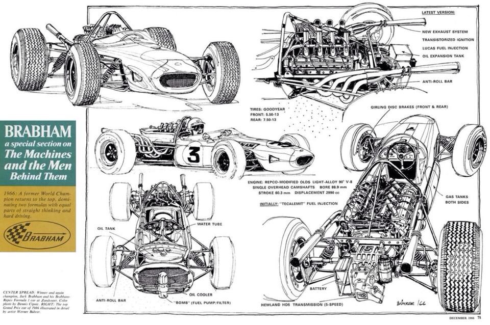
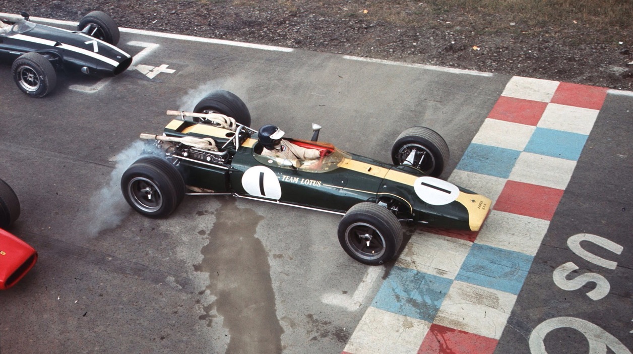
1966 Repco-Brabham 620 3-litre V8: When Coventry Climax decided not to continue, for a solution Jack Brabham turned to his home country Australia. Australia’s Repco was one of the nation’s major manufacturers of automotive parts and workshop equipment. One of its units, the engine parts group under Bob Brown, had made redesigned and improved replacement parts for the 2.5l Climax FPF-four that were being raced in Australia and New Zealand under the Tasman formula; key players in the project were engine part’s chief engineer Frank Hallam and laboratory manager Stan Johnson.
Impressed by the work Repco had done on the Climax engine that he had used to win Tasman races Brabham conceived a plan, if he could provide a basis – a cylinder block, say - he might persuade Repco to design and build an engine around it. ‘I had been up to Japan and had a look at aluminum blocks, he said, and then I went to America and decided that the best block to use was the F85 Oldsmobile’. In a fit of brave innovation, GM had introduced aluminum engines in 1961 for its Buick special and Oldsmobile F85. Though the engines were no longer in production, the blocks were readily available. Having first conferred with Hallam to confirm feasibility, Brabham sold the project to Bob Brown on the grounds that it would bring global publicity to Repco at a time when it was seeking to expand outside Australia. Brown in turn successfully presented the idea to Repco board . they authorized engine parts and its parent in the group, Russell Manufacturing to spend stg 10000 on building Jacks engine.
A talented engineer, Ross Kirkham, joined the team as project manager, much of the machining in Australia was done by Peter Hollinger, and to assist in the V8’S design they engaged as a consultant and draftsman Phil Irving, who had contributed to the successful Vincent motorcycles and was well-connected in the UK, where he went early in 1964 to draw the engine in close consultation with Brabham. Jack’s suggestion of the GM block as a basis was accepted, they opted for the Oldsmobile F85 block of 1961-63 era with six-studs pattern each cylinder. this was the core of the Repco-Brabham type 620 V8 - RB 620 for short. In the Repco numbering system '600' stood for the block and '20' for the cylinder head.
Their aim was to have interchangeability as the head design progressed. Like the Oldsmobile engine on which it was based, the RB 620 required only one LM23WP aluminum cylinder head casting which was machined differently to suit both banks, hidfural 5, a copper alloy, was used for the valve guides, the center portion of the exhaust-valve guide was finned and exposed to the flow of water after the Climax FPF model. Coolant entered from manifolds along the sides, which directed the water to the heads and left the cylinders to seek their own coolant through a few ports in the block/head interface.
Irving placed the valves in a plane inclined inwards at 10 degrees from the vertical, in order to make the engine narrower to reduce frontal area. The inclination required the head to have a shallow wedge-type combustion chamber into which austenitic cast-iron valve-seat inserts were shrunk. Valve sizes were 41.3mm inlets and 34.9mm exhaust. Valve gear was conventional, using chilled cast-iron cup-type tappets the same diameter as the exhaust valves and sliding directly in the head. Dual coil valve springs exerted 100kg pressure at the maximum lift of 10.2mm. No separate tappet block or cam carrier was needed for Irving’s compact design.
Each camshaft rested in 5 bearings in the head, which had bearing inserts only in the removable caps. Oil entered the hollow camshaft through its frontmost bearing and was distributed internally to its sisters. Cam timing was based on that of the Cosworth SCA which had inspired the cylinder head, finned magnesium covers enclosed the cams. A 2 piece magnesium timing case containing a 2-stage Renold roller-chain camshaft drive of 3/8 inch pitch was used. The first stage was a double-roller chain from the crank nose to a half-speed sprocket, which drove a jackshaft positioned where the central camshaft for the push-rods used to be, just outside the timing case, was positively driven the half-speed jackshaft drove the second stage of the chain system. A single-roller chain passing around a camshaft sprocket on the left bank, then below a centrally mounted adjuster sprocket and back to the jackshaft. The longest unsupported length of chain was only 8 inches.
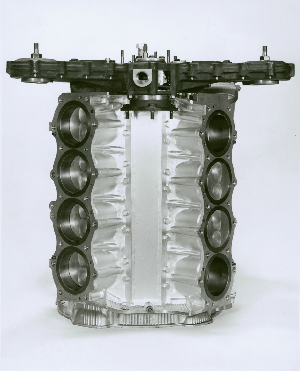
The Oldsmobile cylinder block was suitably modified to undertake its new duties, in the central vee unneeded metal was machined away and the vee sealed by an aluminum plate which was Araldited in place. The standard 88.9mm F58 bore with a stroke of 60.3mm for 2996cc was used. The standard dry cast-iron cylinder liners cast in place in the block was retained.
The block was machined for an appropriate crankshaft oil seals and 2 studs rep-laced bolts for each main bearing caps. A ladder-shaped plate of duralumin was affixed to the bottom of the block, which extended down well past the crank centerline. A conventional racing oil pump was used bolted to the stiffening plate and were gear driven from crank nose, pressure was 75psi. Full-flow oil filter was used + gause screen covering the dry sump and large magnetic plugs in both the scavenge and pressure pumps.
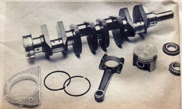
A single plane 180 degree crankshaft fully counterweighted and machined from a solid billet of EN40 steel was used. Die-cast aluminum slipper type pistons with flat tops with valve clearance pockets gave a compression ratio of 11:1. Plain iron compression ring, a multi-seal ring and a chrome-plated segmental oil ring were used. 22.2mm gudgeon pin retained by circlips was used. Piston assembly weighed 510 grams. Forged steel ‘I’ section con-rods from the 4.5l Daimler V8 were used. Repco R77 copper-lead matrix overlaid by babbit on steel backing bearing were used.
Crankshaft was drilled end to end with oil passages. Lukas electronic ignition and fuel injection were used. The first RB 620 roared into life on dyno at Richmond in Victoria on 21 March 1965 pumping 285bhp@7500rpm. The heist power used for racing in 1966 was 298bhp.
Specifications:
Cylinders V8.
Bore 88.9mm.
Stroke 60.3mm.
Stroke/bore ratio 0.68:1.
Capacity 2996cc.
Compression ratio 11.0:1.
Con-rod length 160mm.
Rod/crank radius ratio 5.3:1.
Main bearing journal 58.4mm.
Rod journal 50.8mm.
Inlet valve 41.3mm.
Exhaust valve 34.9mm.
Inlet pressure 1.0 atm.
Engine weight 136kg.
Peak power 298bhp@7500rpm.
Piston speed corrected 18.0m/s.
BHP/litre 99.5bhp/litre.
Engine weight/bhp 0.45kg/bhp.
I seem to have said on 24th June 2013 that ......
some sources said the Tipo 8 was designed by some of the people who left Ferrari en masse in 1962 and ......
then designed again for Honda
the Pritchard book 'Grand Prix Ferrari ...' P238 and the Whitelock book P310 mention the industry belief then that ....
Ferrari (ie Chiti) worked on (aircooled) transverse engines springing from earlier friendship and cooperation with Gilera
in March 1962 Ferrari said they had aircooled F1 engines (remember Porsche was a big thing at that time)
the Tipo 8 of course has the bore and stroke of the Gilera
Chiti and 7 other managers threatened Ferrari over Laura Ferrari's interference and were sacked in late 1961
Chiti with Tavoni and others from Ferrari created the new F1 ATS team and car
others it seems went to the Maserati brothers (who weren't the Maserati company) and to Lamborghini etc etc
Honda was all over F1 and studying it (even trying to cut an engine supply deal with Lotus)
but also particularly busy redesigning its 50cc 125cc 250cc and 350cc GP motorcycles to beat intense competition
I imagine (others don't) Honda would want to look at the design then called the Tipo 8 (and its available designers)
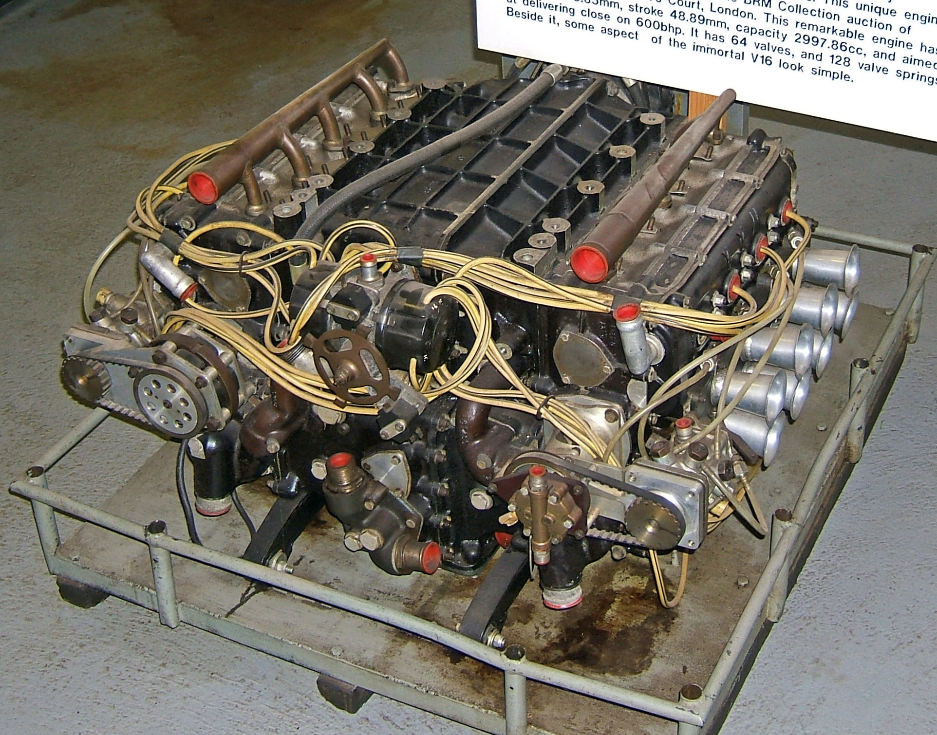
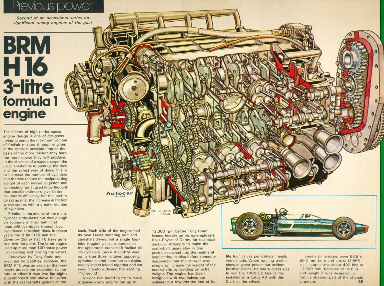
1966 BRM P75 3-litre H16: BRM’s staff at Bourne in Lincolnshire were given the green light to plan new cars for the 1966 3-litre Formula1. In charge of the effort was Tony Rudd, who had succeeded Peter Berthon as BRM’S technical director. Chief engine designer was Geoff Johnson. A 12-cylinder was considered, Rudd’s choice fell on a radical 16-cylinder engine composed of 2-horizontally opposed 8’s placed one atop the other and geared together. Estimates were that it would weigh 176kg and produce 500bhp – figures which, in the event were destined to be changed.
Rudd’s reasoning was that the H16 could use the proven and effective porting, valve gear, combustion chamber, pistons, con-rods and cylinder liner from the successful 1-1/2-litre V8. In the last V8 the inlet ports had been resited between the camshafts to flow down from the top of the cylinder head, so they were at the sides of the H16. The exhaust ports were at the top and bottom of the engine.
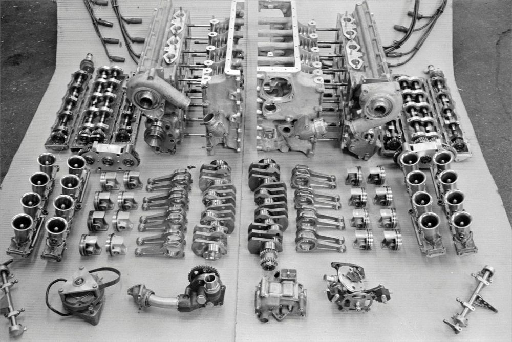
The initial plan was to place one flat-eight atop the other in such a way that they would share a single inlet camshaft along each side. However, a need for increased clearance between the crankshafts blocked this scheme. If a single inlet camshaft had performed double duty it would have forced an angle between the valve stems that was excessively large. In fact Rudd and Johnson then chose narrower valve angles that those of the V8, 23 degrees for the inlets and 29 degrees for the exhausts, which required a slightly larger bore to accommodate the valve heads. The H16’s cylinder dimensions were 69.85x48.89mm compared to 68.5x50.8mm for the V8. With this move the interchangeability of pistons and liners with the V8 was forfeited. And weight rose with 8 instead of 6 camshafts. Each side of the engine was capped by a single aluminum-alloy head – a fantastically intricate casting.
Weight rose further with the inclusion of some features in the bottom-end design that made the 16 easier to assemble. Akin to a nearly square box cast of LM8 aluminum alloy, the crankcase was split vertically 63.5mm to the left side of its centerline to permit both crankshafts to be installed in the right-hand or primary half with separate caps for the 5 57.2mm-main bearings, then the smaller secondary half of the crankcase was attached with separate through-bolts.
The 2 cranks were geared together by a separate pack of 3 19mm-wide spur gears at the rear of the engine, mounted in ball and roller bearings. The roller bearings were inset into the rear panel of the crankcase and the ball bearings were carried by a separate bolted-on magnesium housing. Each crankshaft was connected to its gear by a short splined torsion shaft made of EN40 steel.
The cranks were initially of simple flat 4-cylinder design with side by side 115.6mm con-rods on a common journal, located at 90 degrees to each other by the output gearing. 2-cylinders fired together in the upper 8-cylinders, then 2 in the bottom 8 90-degrees later. All 8 camshafts were driven from the nose of the lower crankshaft only the 2-stage gear packs originally created for the V16 drove the lower camshaft from their crank. The gear on the lower inlet camshaft drove the upper inlet cam and through an idler gear, the upper exhaust camshaft. This introduced a long gear train between the lower crank and the topmost camshaft and an even longer train from the upper crankshaft, which was linked to the lower shaft by the output gear pack.
Lucas transistor ignition trigger and its distributors for the whole engine were driven directly from the front of the upper crankshaft at half engine speed. 2 water pumps, each powered a completely independent circulation and radiator system for its heads and 2 fuel-injection metering units were driven from intermediate valve-train gears at front of the H16. The oil pressure and scavenge pumps were gear-driven from the lower crank. Small pumps driven by the lower exhaust camshafts scavenged the lower camboxes.
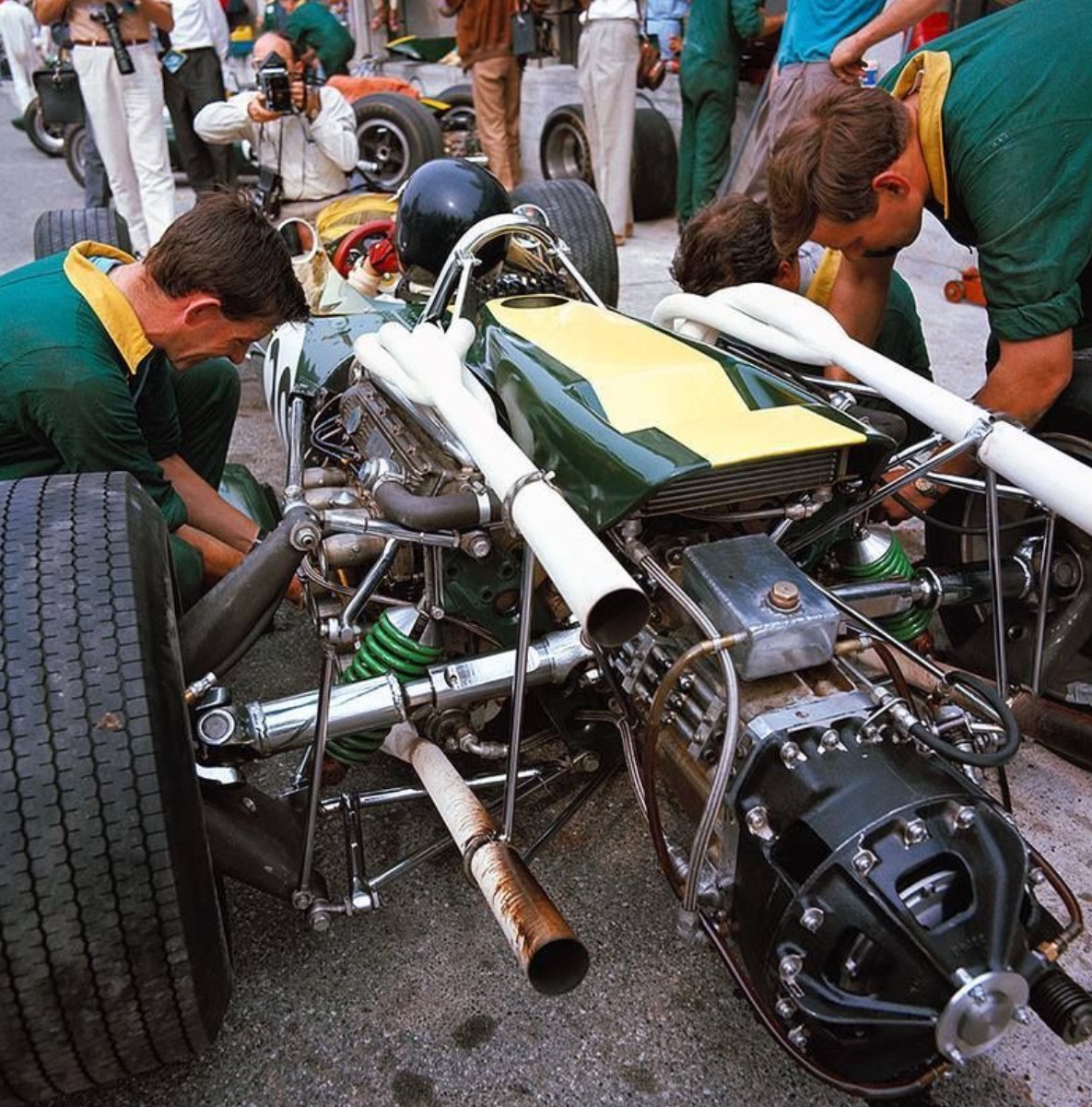
The new H16 was also to be supplied to team Lotus for its Grand Prix cars and in special 4.2-litre version for a 1966 Indianapolis effort. In the USA the engine displayed an awe-inspiring repertoire of failure modes. The cogged rubber drive belts to the Lucas fuel-metering units broke, as did the lower inlet camshaft where its drive gear was attached. Outrigger bearings were made for these, and flywheels were put on the drives to the metering units to damp their torsional vibrations, gear and center bearing failure in the output train between the crankshafts inevitably had expensive results, with the upper crankshaft’s valves being timed from the lower crank nose. Severe torsion vibrations affected the output gear train’s centre gear and bearings, which received twisting impacts from both crankshafts at alternating intervals and in opposed directions, the mass of the 4 of the crank counterweights was increased by 0.9kg apiece by bolting and welding a steel inertia ring to each one. This modification, crude though it was proved effective, and it was then possible to install the engine in a car.
It was also possible to obtain meaningful power figures for the first time. The highest output ever measured by BRM from its H16 was recorded in June 1966 from engine number 7504, a unit destined for delivery to Lotus. It returned 402bhp@10500rpm. In the first year of the 3-litre formula 1, that was a lot of horsepower. At Watkins Glen late in 1966 was engine number 7502, a heavily salvaged unit with metal plates and patches of Araldite holding its crankcase together. Giving 375bhp, this was rushed into service to win the US Grand Prix – the only victory ever credited to the H16.
Over the 1966-67 winter intensive development attention was given to the H16’s many problems. A new steel/steel material combination stopped excessive wear of the camshafts and tappets. Overheating was tackled by fitting a circulation system that prevented vapor locks in the complex heads from stalling the water pumps. Con-rods cracks were intercepted and cylinder-head studs failures were overcome, as was piston-ring breakage.
A major change allowed the H16 to run as a sequential 16, with one cylinder firing every 45 degrees of output shaft rotation. This required new crankshafts with 8 individual throws to give a firing order that allowed tuned scavenging exhaust pipes to be used. For these ‘8-pin’ mark-2 engine the diameter of the big-end journal was increased to 47.6mm to enlarge the area of overlap between the main and rod journals. New crankcase castings were also needed because the offset between facing banks of cylinders had to be increased from 0.65 to 1.05 inch to accommodate the required counterbalances, and new con-rods were required.
The weight of the mark-2 engine rose to no less than 236kg, but its output showed no advance on the typical level of 380bhp. In spite of all these improvements the mark-2 type 75 was still prone to occasional catastrophic failure. Valve breakage was identified as the culprit. The torsional flexibility allowed by the camshafts and their drive gears permitted the valve timing to drift enough to allow the valves to touch during overlap. Eventually a head broke off, usually the inlet valve. The piston hammered the head against the cylinder head, buckling the con-rod and shattering the cast-iron cylinder liner. Steel liners were fitted, they were batter able to contain the damage. A slight reduction in valve sizes and closer attention to valve timing cured this fault that had wrecked so many engines.
The last race entry by the BRM H16 was in the first event of 1968 South African GP, in which Mike Spence retired after 8 laps, as part of a complete BRM car, the engine had done no better during its career than a second place at Spa in the Belgian GP in 1967, with Jackie Stewart at the wheel.
After its initial tests the 4.2-litre Indy H16 engine posed so many problems that it had to be abandoned. It is an incredible but a documented fact of motor racing history that a single organization, BRM, suffered 2 total debacles in its flirtation with the undeniably-attractive 16-cylinder racing engine. The first 16 was build and run against all the financial odds. The second 16 was possible only because there were few constraints on finance. Both carried flaws of design and execution that kept them from developing their projected power and endowed them with a formidable capacity for self-destruction.
Specifications:
Cylinders H16.
Bore 69.85mm.
Stroke 48.89mm.
Stroke/bore ratio 0.70:1.
Capacity 2998cc.
Compression ratio 10.5:1.
Con-Rod length 115.6mm.
Rod/crank radius ratio 4.7:1.
Main bearing journal 57.2mm.
Rod journal 47.6mm.
Inlet valve 39.7mm.
Exhaust valve 30.5mm.
Inlet pressure 1.0Atm.
Engine weight 236kg.
Peak power 380bhp@10500rpm.
Piston speed corrected 20.1 m/s.
Engine BHP/lite 126.8 BHP/litre.
Engine weight per BHP = 0.62kg/bhp.
the H16 weirdly had the clutch (body) on the gearbox input side not on the engine output side aka the crankshaft
afaik causing chronic shift problems treated by improvising increased crankshaft inertia with added 'inertia rings'
the problems this caused were cured only by going to one crankpin per cylinder
afaik the (then) weird clutch position was because 4 wd adaptability was demanded after design had started
its conrod ratio was even longer than the V8s - then Tony Rudd found 'long' rods were a bad match to combustion rate
and the 64 valve version had port dividers that were too short for proper 'tuned exhaust' effect (said TR)
the H16 had the first totally structural engine/transmission (the Lancia D50s of course was only part of the structure)
btw the Alfa Romeo Tipo 160 had a totally structural 'chassisless' engine/transmission but a complete car wasn't built
BRM designed (and made ?) the whole Matra V12 below the heads
and the 1.5 1.9 2.1 and 2.2 litre V8s (including trying 32 valves and 4 wd)
and their own-block 1 litre F2 4 cylinder
and 24 valve 2.5 and 3.0 litre and 48 valve 3.0 litre V12s and 3.0 and 4.2 litre 32 valve and magnesium 3.0 64 valve H16s
and the transmissions ... and the cars
more or less all at the same time
some said their big problem was Jim Clark - a '1 man team' using a '1 man engine' ?
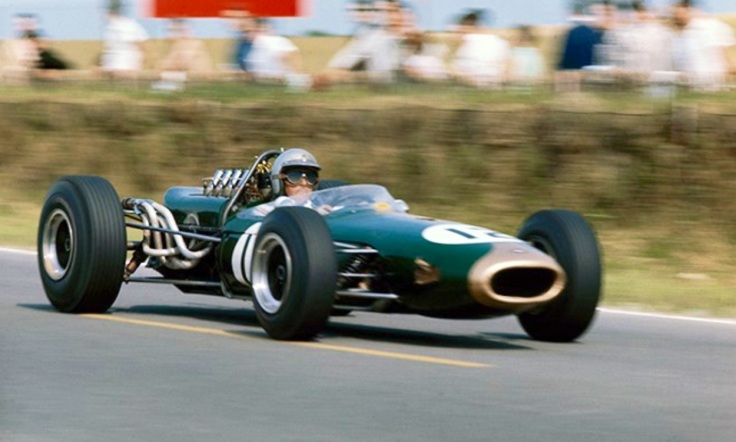
the Repco-Brabham won GPs using a wet sump (with sliding baffle plate)
btw 1
Setright seems correct that R-B used the $10 Daimler 4.5 litre rods (not the better-known 2.5 litre)
the Olds rod was 5.66", the Daimler 2.5 litre 5.5", and the 4.5 litre 6.3"
ie the Daimler had a low deck to minimise width suitably for UK-size cars
about 1800 4.5 litre engines were built - many went into (120 mph) 8 seat limousines and hearses
about 1 was used in amateur racing (sadly not Can-Am)
(though the 2.5 when supercharged won the UK hillclimb championship)
btw 2
the transverse Honda F1 V12 gearbox ran at 44% of crankshaft speed
this would reduce the rotational energy lost in shifts (despite the gearbox needing greater torque capacity)
additional to their packaging benefits, this acceleration benefit would be available to all transverse gearboxes
(these first appeared in the late version of the W25 Mercedes-Benz)
so it would be interesting to know what crankshaft-to-gearbox reduction ratios were in the front-engined era 1936-1960
Last edited by Tommy Cookers on 03 Apr 2019, 15:48, edited 2 times in total.
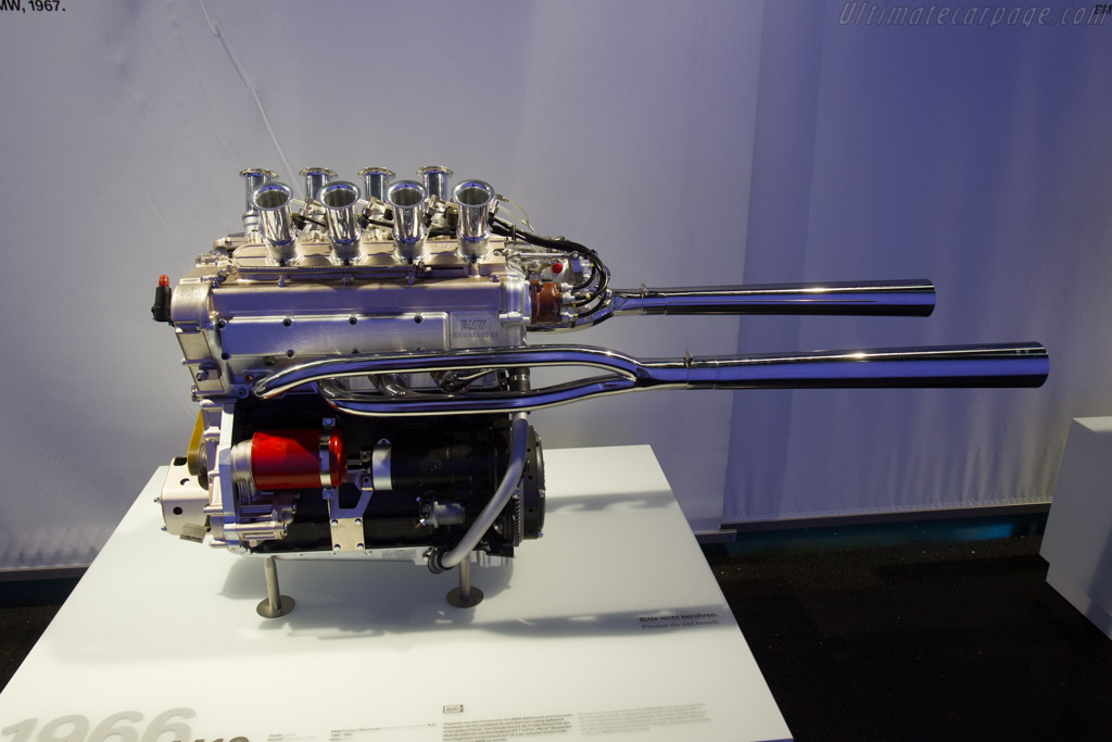
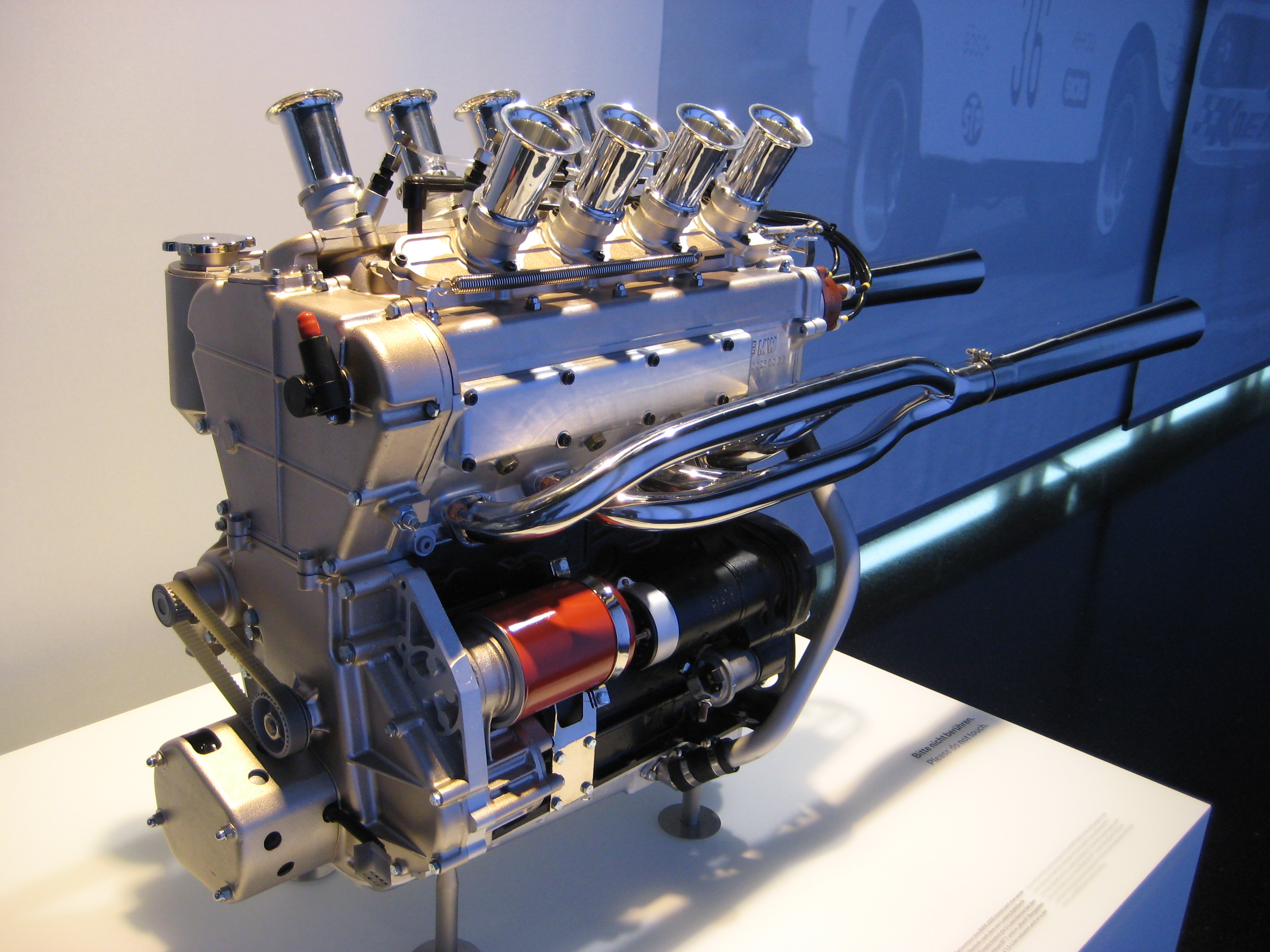
1967 BMW M10 2-litre four: In 1966 BMW astonished the racing world with its disclosure of a completely new engine concept that promised exceptional performance. Ludwig Apfelbeck had been quietly but effectively beavering away in BMW’s engine labs since he joined the Munich firm in 1957 at the age of 54. Gradually he had gained acceptance for a pet idea. His notion was that a pure hemispherical combustion chamber with radial valves could offer an optimum in both breathing and combustion.
A conventional hemispherical chamber with 2 inclined valves comes close to the optimum shape but Apfelbech’s idea was to add 2 more inclined valves in a plane rotated 90 degrees to the first 2 valves so that in plan view the valves stems pointed to all four points of the compass. This was not wholly new, among motorcycle makers the layout had been tried by several including Rudge. Ludwig Apfelbech added a new twist , instead of pairing like valves side-by-side he placed them diametrically opposed each other and he thus named his diametral combustion chamber. The inlet valves faced each other and the exhausts likewise.
Among the advantages he saw for this were the cooling afforded to the exhaust valve seats by the adjacent inlets, and the very effective scavenging of exhaust gas from the chamber by the incoming fresh gasses. With a plan for such a head on a 4-cylinder block and excellent gas-flow results from bench testing, Apfelbech convinced BMW’s technical chief Klaus von Rucker of the merits of his idea. Von Rucker gave the green light on a single-cylinder lab engine. This gave such good results – 64.5hp from a 500cc cylinder – that BMW commissioned the building of a diametral head to fit on the iron cylinder block of its standard 2-litre 4-cylinder passenger-car engine. Within cylinder centre distances of 100mm, this provided 89mm bores. Combined with an 80mm stroke its swept volume was 1991cc.
The work was done with the support of BMW’s outstanding and experienced engine team of Alex von Falkenhausen in overall charge, Paul Rosche dealing with engine’s bottom end and Otto Stulle coping with development. By 1966 the M10 engine as it was designed, was ready for testing. Right from the start the engine reached 264 bhp on gasoline and indeed 310 bhp on racing fuel - “methanol with a dash of nitromethane”. The output on gasoline was equivalent to 133 bhp/litre – even better than the test engine.
The cast-iron cylinder block of the standard BMW 2000ti touring car extended well down past the crankshaft centerline, enhancing the stiffness of the bottom end. The caps for the 5-main bearings were specially prepared but were retained as standard, by 2-cap screws. The required bottom-end strength was provided by the fully counterweighted crankshaft, which resembled the standard part but was forged of special steel and machined to suit this application. I-section con-rods were 135mm long, and made of titanium. They weighed 440 grams as against the 550 grams of the steel rod.
Forged Mahle pistons of slipper type with 2-compression rings and 1-oil ring were used. The crowned top of the piston was pockmarked by 4 craters corresponding to the position of the radially positioned valves, provided the required clearance at and near TDC.
A small spur gear on the crank nose turned a half-speed gear that was above and slightly to the left of it. A sprocket coaxial with this gear drove a double-roller chain that extended up to the engine’s twin overhead camshafts. This was in tension on the right side of the engine, where it was paralleled by an anti-flutter guide. The chain was tensioned by an adjustable idler sprocket on its slack left side. The half-speed gear mated with another spur-gear, to the left and downwards, which turned a gang of 2 gear-type oil scavenge pumps. These drew from the shallow dry sump. A pressure pump delivered Castrol lubricant through the block's integral passages, and through an external hose on the left, to oilways inside the camshafts that released it onto the cam lobes´ surface.
A pulley on the crank nose drove a v-belt to a water pump mounted on the right side of timing chest. This delivered coolant to the left rear of cylinder block.
Ludwig Apfelbeck worked miracles in the pre-computer-aided design era in devising a way for 2-overhead cams to operate his radially disposed valves, the exhaust valves were at the sides of the chambers and the inlets disposed between them. In their respective planes the inlets were at an included angle of 54 degrees and the exhausts at 62 degrees. These angles were compatible with the hemispherical combustion chamber and with the associated valve ports as well. The inlets could not simply be in the longitudinal plane of the head, their stems would clash. So the complete chamber was rotated by 31 degrees clockwise in plan view so that the inlets stems would parallel each other instead of conflicting. The exhaust ports still made quick exits from both sides of the head, each side had its own tuned exhaust manifold. The only solution for the inlet ports was to bring them down from the top of the head. This was a happy echo of BMW’s 328-6, which also had downdraught inlet ports. The ports rose to the flat plane of the top of the head. Between them were the smaller apertures for the 12mm spark-plugs, which were at the very centre of each chamber. Large 41mm inlet valves and 34mm exhausts were used, inlet valve lift was 11mm and the open duration was 324 degrees, dual coil valve springs were used.
Then there was the matter of the valve gear. How to operate 16 radial valves?. Apfelbeck made it easy. Contacting the stem of each valve was a short finger, pivoted to swing in the plane of the valve. Atop the end of the finger was a cup. Into this cup fitted the spherical end of the screw-adjustable tip of a roller-faced follower that swung from a pivot shaft below and inboard of each camshaft. The roller follower transmitted the cam’s motion and the finger translated that motion into plane of valve.
The screw adjusters for the running clearance of the inlets were easily accessible from the top of the head, but those for the exhausts had to be reached through square ports in the sides of the head. The camshafts ran directly in the aluminum of their five bearings in the head. The M10 head was a single complex casting right up to centerline of camshafts. A cast light-alloy cover enclosed these and the valve gear and provided a base and mounting for the 8-separate downdraught carburetors that were initially fitted, each was a Solex 40 PJTC units with a 40mm throat; instead of a float chamber each Solex contained a weir which was supplied by one fuel pump and was scavenged at proper level, by another pump. To improve throttle response one row of carburetors opened initially. At one third throttle on that bank, the other row began to open gradually catching up with the first row. Later on the carburetors were replaced by Lucas fuel injection, with separate slid throttles and short ram pipes for each row of inlet ports.
Specifications:
Cylinders l4.
Bore 89mm.
Stroke 80mm.
Stroke/bore ratio 0.90:1.
Capacity 1991cc.
Compression ratio 10.5:1.
Con-rod length 135mm.
Rod/crank radius ratio 3.4:1.
Main bearing journal 55mm.
Rod journal 47mm.
Inlet valve 42mm.
Exhaust valve 34mm.
Inlet pressure 1.0Atm.
Engine weight 145kg.
Peak power 280bhp@8800rpm.
Piston speed corrected 24.4m/s.
Peak torque 236Nm@8000rpm.
Peak bmep 217psi.
Engine bhp per litre 140.6bhp/litre.
Engine weight per bhp 0.51kg/bhp.
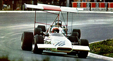
BMW – what to do with such an engine? BMW used it with racing fuel in a Brabham single-seater chassis in December 1966 to break some international 2-litre class standing-start records. It was also fielded by the works in a Lola sports-racing chassis in the European hill-climb championship, for which this was the max displacement allowed, the BMW-Lola placed 4th in the championship in 1967 and 2nd in 68. An attempt to reduce the M10 four to 1.6-litre size of the new formula 2 for 1967 was less successful and led to unfortunate schisms between Apfelbech and his BMW colleagues. Nevertheless in a Lola chassis, this engine introduced BMW to single-seater racing, a field in which it made strong contributions.
Some pictures from stivala:
Show engine:
Show engine:
Factory development engine:
Actual drawing by Ludwig Apfelbech showing the principle of the valve gear used in the BMW M10:
Factory development cylinder head (cams/sprockets, valves and finger followers assembled). A careful study will show 2-individual inlet ports descending to the valves and between them the aperture for the spark-plug (this for each cylinder). Also the roller cam-followers can be seen. Notice the lubricating oil hole on the cam lobe which indicates that the camshafts were hollow.
And some more links about the 1967 BMW M10 2-litre four:
It is a fabulous thread. However I think it lacks a paragraph or two about the success of the engine- not a listing but an informed opinion. The BMW was a disappointment as I recall.
Re the 1967 BMW M10 2-LITRE FOUR (Apfelbech radial valve head).
Yes a lot more could have been said/written from my notes not only about this engine but all previous ones, but it is mostly non-technical, although of great interest, at least to some. Anyhow the 1967 m10 2-litre four (apfelbech radial valve head) was the engine that introduced BMW to single-seater racing. But sadly the attempt to reduce the M10 four to 1.6-litre size of the then new formula 2 for 1967 was less successful and led to unfortunate schisms between Apfelbech and his BMW colleagues.
Moved from the discussion on the Ferrari PU after Leclerc's problems in Bahrain:
64 years after Mercedes introduced their iconic direct injected M196 2.5-litre straight eight in 1955, with back than their in-cylinder-wall installed injector nozzle position just below the inlet valve with centreline of nozzle angled upwards at 12.5 degrees, with fuel flow beginning at 30 degrees ATDC on the inlet stroke and continuing for 160 degrees. We are here debating this now modern in cylinder direct injection and what possibly happened or not on the number 16 FERRARI car in Bahrain GP.
that would be 1954, with the first production 4 stroke GDI car (the 300SL) in 1955
at that time Bendix aero engine 34 bar GDI injected 'at 25 deg btdc' - quicker than the W196's ? (only 3000 rpm of course)
the first production GDI aero engines were the DB601 and Jumo 211 in 1937
they began injection at c.100 deg btdc and finished at tdc
the first production 2 stroke GDI car was the Goliath in 1952, then the Gutbrod in 1953