Modatek describe their new manufacture DFV throttle body as 'anodised black'
note to self -
Pylumin was a chemical etch process making the surface aluminium oxide with chromate ions - a foundation for top coat
this is not anodising
re the Weslake engine
there was a BRM/Shell/Weslake R&D setup - then Weslake bought out the BRM share
(BRM had just tried 4 valves and Weslake had earlier done the same for Norton in the 50s ?)
posterity has recognised the Weslake's '2 litre BRM-like' rather low bore:stroke ratio - not helping it to be a 'DFV-beater'
the Castrol man told me that the 1967 Race of Champions was won on Agricastrol ('farm') oil
on page 9 of the Technology category in this site's Technical (not Forum) section .....
the article 'PLAN 2 - Torque & Power' ....
features Roy Franklin's design work on the Weslake engine (the Shell 2 cylinder test unit anyway)
“Known more for its expertise in gas-flow management than for engine manufacture, Harry Weslake’s establishment on England’s south coast at Rye was not an obvious candidate to build a new Grand Prix engine. It did, however have the services of refuge from BRM, designer Frank Aubrey Woods, and a promising parallel-twin research engine build under a research contract with SHELL. This ran initially in 355cc form and later, in the summer of 1965, as a 500cc twin – one-sixth of a 3-litre V12. The 500cc twin was making 76 horsepower, Dan Gurney recalled, which times six is something like 450 horsepower. Nobody was making that kind of power at that time”.
Westlake also made head conversions for Triumph motorcycles. Few and far between but I did see some.
TRIUMPH T140W TSS GETS A NEW 8-VALVE HEAD
Westlake, a cylinder head designer with extensive racing experience with Jaguar and the like, put together an 8-valve top end and a new crankshaft for the Bonneville engine. Of course, 4-valves-per-cylinder are quite common today, but in 1982, it was considered exotic racing tech. Each of the 4 valves were smaller than their 2-valve counterparts, with two for intake and two for exhaust in each cylinder, set at a much steeper angle than before. The 2-valve Bonnie has a true hemispherical combustion chamber with its valves set at a 90-degree included angle. The new Westlake head set them at 30-degrees. The pistons were deeply notched to clear the valves, so taller domes allowed a 10.0:1 compression ratio. The alloy cylinder block had steel liners.
“Triumph T14W TSS gets a new 8-valve head” Yes the 2-cylinder cylinder head had 8-valves!. “In 1982 it was considered exotic racing tech”. The 1913 Peugeot L3 3-litre four was the first car of any kind to combine a ‘VEE’- inclined 4-overhead valves per cylinder cylinder head and twin overhead camshafts driven by a train of gears instead of by vertical shaft/s and operating the valves through finger-cam follower. Later on as regards the Triumph motor cycle “Triumph Ricardo the motor cycle June 2nd 1921 page 688”:- A four valve engine for the TT. (Triumph four valve 192 – Sheldon EMU.)
reminding myself - 4 valves per cylinder (with sohc) were standard for GP cars eg Fiat S61 S74 well before the Peugeot
eg even the 28.4 litre S76 'Beast of Turin' running today
4v was and remained standard for water-cooled aircraft engines - emulating the 1914 GP Mercedes
the question was ....
how did 2v become and remain the GP standard pre-DFV ? (and Weslake)
BRMs 4v V8 was never adopted and Coventry Climax's even in 1965 was quite unconvincing
in 1923 Fiat remade the GP world via supercharging
with 2 valves and big VIA and combustion chambers 'bulged' wider than the bore (anyway usual with 4v)
1924-1964 2v was broadly the GP king (except for 1930s Mercedes-Benzes and very few others)
the answer seems to be something to do with 4v needing (even more than 2v) a narrow VIA for quick combustion
not unrelated to fashions in bore:stroke ratio
some famous winning engines eg Peugeots were anyway over-valved and over-ported
History records shows the 1912/1913 Peugeot were the first cars in the world (first of any kind) to combine a ‘vee-inclined overhead-valve cylinder head with 4-valves per cylinder and twin overhead camshafts operating the valves through finger cam-followers. This was the engine design acknowledged by historians as the engine design that have shown the way forward as regards race engine design.
Yes as all or most engines of the period the Peugeot L3 was over-valved and over-ported as were some engines of much more modern times, gas flow technology pre computer use as a tool was not fully grasped by many engine designers, and even the few of the gas-flow calculating tools of the time were known about. I remember reading Keith Dugworth saying before the DFV was borne that on a visit to an engine workshop in Australia he had noticed/seen a sort of test bench that might have been used to flow cylinder heads.
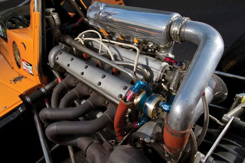
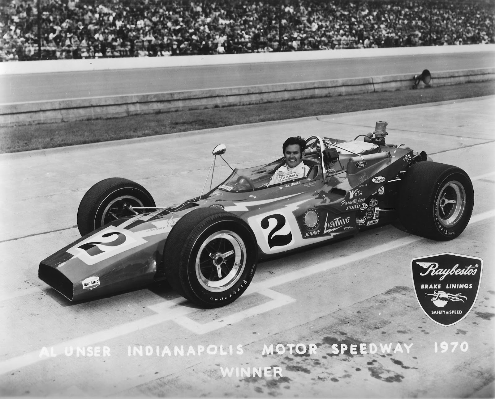
1970 Drake Offenhauser 2.6-litre four: The Offy might have died in 1933 with the bankruptcy of Harry Miller, the great visionary who created it. Design techniques proven in the great Miller straight-eight-cylinder racing engine of the 1920’s had been used by Miller and his team to make a 2.5-litre four cylinder unit for boat racing which also showed, by chance, excellent performance in a racing car. At first limited by racing rules to 2-valves per cylinder, the engine was given 4-valves by engineer Leo Goossen when this was allowed in 1931. Progressively scaled up in size year by year, the engine was a 3.6-litre four in 1933 when Fred Offenhauser bought the tools, drawings and patterns to make it from a bankrupt Harry Miller.
He set up his own one-man Offenhauser engineering company, which became two-man when Leo Goossen, the designer who had always interpreted Miller’s vision, joined Offenhauser, whose engine soon became known as Offs, thus when the four first won Indianapolis in 1934 it was already officially an Offenhauser engine, of 4.2-litre size. The 1934 win was the first of no less than 30 victories the Offy scored in the 500-mile race until 1976. In many years, especially in the 1950’s the Offy totally dominated Indianapolis, in 1954, on the first of several such occasions, all 33 of the starting cars at the speedway were powered by the four-cylinder Offy.
The Offy used in US championship racing had four valves per cylinder operated by gear-driven twin overhead camshafts raising the valves through inverted-cup tappets, the head and cylinders were a single casting, originally of iron and, since 1969 of aluminum with inserted dry liners. The separate crankcase was aluminum, of tunnel-type construction into which the crankshaft, with its 5-main bearings bulkheads, was inserted from one end. To suit US racing rules the Offy was enlarged to 4.5-litres in 1938, in 1946 the rights to the engine were bought from Offenhauser by Lou Meyer, three time Indy winner, and Dale Drake, their Meyer and Drake engineering continued to produce the Offenhauser engine, rule changes brought it down to 4.2-liters again in 1957, by then fed its alcohol fuel through Hilborn constant-flow port-type fuel injection. Offy customers led the way toward a new short-block configuration for the reduced-size engine.
With Lotus as its ally, Ford mounted a concerted attack on the Offy, beginning in 1963, it nearly won a controversial 1964 race and finally, in 1965 Jim Clark’s Lotus-Ford beat the Offy-powered roadsters, but unwilling as he was to give up on the great engine, Dale Drake built a new factory to produce the Offy in California’s Costa Mesa, near the Orange county Airport. He was joined by his son John, by Leo Goossen and by Walt Sobraske, master machinist who first worked for Harry Miller in 1921.
While Ford was making unsupercharged 4.2-litre eights, Drake decided to make the supercharged 2.7-litre fours that the rules allowed. Drake had a sound basis on which to do this, because the Offy was well-suited to supercharging with its four valves per cylinder and integrated head/block design, avoiding gasket problems. Also supercharged predecessors had been built and raced. A 3-litre Offy of the 1950’s was based on the 220 block and crankcase, a direct descendant of the original marine engine of 1931. In 1950 with mechanically-driven centrifugal blower, 3 qualified for the Indy 500 but none finished. One qualified and failed to finish the next year, and in 1952 one blown qualifier retired during the race. A blown Offy also qualified in 1957 when the supercharged-engine displacement limit was cut to 2.8-litres. It too, failed to finish.
Supercharging’s second wind was in large part the inspiration of Dick Jones, operator of Champion’s West Coast dynamometer facility and a man eager to see the Autolite-sparked Fords beaten. Jones carried out some tests with a Roots-type blower which yielded a much fuller torque curve than the centrifugal units. In the late 1965 Leo Goossen designed a proper engine to suit the basis of the robust crankcase of the 4.2-litre Offy four and using the shorter gear tower of the 220 variant of which had served for the experimental engine build by Jones. This new Offy had 144 mm tubular-shank con-rods and a suitable altered cylinder block.
Well oversquare at 104.8*79.5mm for 2.739cc, it weighed 216kg. It had its 4-vlaves equally inclined at a 72 degrees included angle in a pent-roof combustion chamber, with a single central spark-plug ignited by a Scintilla magneto prepared by Joe Hunt. Valve diameters were 39.7mm for the inlets and 34.9mm for the exhausts. Lift by the direct-acting radiused top tappets held in proper alignment by a keyway was 10.2mm, and duration was 290 degrees for the inlets and 270 degrees for the exhausts cams. Valve spring pressure was 73kg static and 163kg with the valve fully open.
Machined from a billet of SAE 4340 steel, the crankshaft was fully counterbalanced and turned in thin-wall copper-lead bearings 60.3mm in diameter. Rod journals were 54mm. Gudgeon pin was 27mm diameter, pistons, carrying 2-compression rings and 1-oil ring, were configured to provide an 8.5:1 compression ratio. Rob Debisschop of AiResearch provided an exhaust-driven turbo-supercharger and Stuart Hilborn of the eponymous fuel-injection company helped him work out the piping and fuel delivery to adapt it to the new Offy. Mechanic Herb Porter was an important ally of the project.
On the champion dynamometer Jones found that the turbo-blown engine produced 626bhp@8500rpm against 530bhp for the roots version at the same speed. In fact, the turbo-blown engine’s power curve was almost a direct extension upwards of the output of the blown Offy of 1954. Both produced 500bhp at 6500rpm but that was where the old one stopped. The late-1960 version could rev safely to 9500rpm. The turbo-Offy’s staggered the first drivers to try them “It’s the first engine I can’t drive full-bore off the corners”. Both versions of the engine appeared at Indy in 1966, 3-of each kind making the field, and all had problems, especially with cooling. The highest placed at the finish was Bobby Unser’s 8th, a turbo-blown model. The next year 7 of the 8 qualifying Offy’s were turbo-blown units, with 2 of them placing 7th and 8th at the finish.
No small amount of development was needed to get the engine to the point where it could win for Bobby Unser in 1968. At first it overheated severelly, water passage size increases helped and later the block was made asymmetrical for the first time to add more water capacity around its exhaust ports, which were divided into 2-ports with a small water passage between them. Internal pipes directed cool incoming water into this passage and onto the inner surface of the exhaust valve seat area.
Crankcase design was changed to gain the needed strength with the higher outputs. With the high heat inputs of the turbocharged engine, block quality was also a problem. The 1966 engine had aluminum blocks, which were unpredictably porous in spite of Drake’s best attempts to seal them. For the new 1967 engines a switch back to iron was made. In 1969 aluminum blocks were back. Thanks to a new foundry, Turner in Bell, California. To shrink the turbo-Offys to 159.4cu-inch to meet the 1969 capacity rules Drake made sets of sleeves which were pressed-in, with a 0.006inch interference fit, to bring the bore down to 102.4mm and the displacement to 2616cc. when these were installed in an old block they created a slight combustion chamber overhang around the edges, the new 1969 blocks had a smaller combustion chamber diameter to eliminate this.
New permanent-mould-cast pistons were provided. Some Offy buyers preferred impact-forged TRW pistons that seemed to give more consistent performance and reliability above 8500rpm. Careful development smoothed out the engine’s torque curve, filling in a former low point at 6000rpm. Joe Hunt’s magnetos were replaced by flywheel-triggered Mallory ignition system. Max torque was 510lb ft at 7000rpm and peak power was 727bhp at 8250rpm with an boost of 24psi.
The engine was further strengthened to stand up to the crew chiefs who liked to add 5-10 percent nitromethane to the methanol fuel. These improvements underpinned the engine’s subsequent success, which included 5-straight victories in the Indy 500 from 1972 to 1976. Not until 1981 did the new engines such as the Cosworth V8 eliminate Offys from the Indy starting field. In 1973, the year of peak supercharged development before limits on boost and fuel consumption were imposed, some engines were being boosted as high as 42psi for Indy qualifying, producing four-figure horsepower levels. On the McLaren engine dynamometer, on 37 psi of boost, the 2.6-litre Offy generated peak torque of 650lb ft at 7600rpm, it produced a max of 959 bhp at 8000rpm and was still delivering in excess of 950bhp at 9200rpm. This represented 369bhp per litre, the highest specific output produced up to that time.
Specifications:
Cylinders l4.
Bore 102.4mm.
Stroke 79.4mm.
Stroke/bore ratio 0.78:1.
Capacity 2616cc.
Compression ratio 8.5:1.
Con-rod length 144 mm.
Rod/crank radius ratio 3.6:1.
Main bearing journal 60.3mm.
Rod journal 54mm.
Inlet valve 39.7mm.
Exhaust valve 34.9mm.
Inlet pressure 2.66Atm.
Engine weight 216kg.
Peak power 727bhp@8250rpm.
Piston speed corrected 24.4m/s.
Peak torque 692NM@7000RPM.
Peak bmep 483psi.
Engine bhp per litre 277.9bhp/litre.
Engine weight per bhp 0.30kg/bhp.
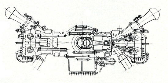
The two engine drawings of this famous and certainly one of America’s greatest ever engines. Is of Leo Goossen’s 1975 developed Drake-build OFFY, showed on the left is the foam that was included in the large breather system on the left side of the crankcase. Characteristic of Miller-derived design was its use of radiused tappet which was keyed to keep it from rotating. The inserted cup around the spark-plug also followed Miller practice.
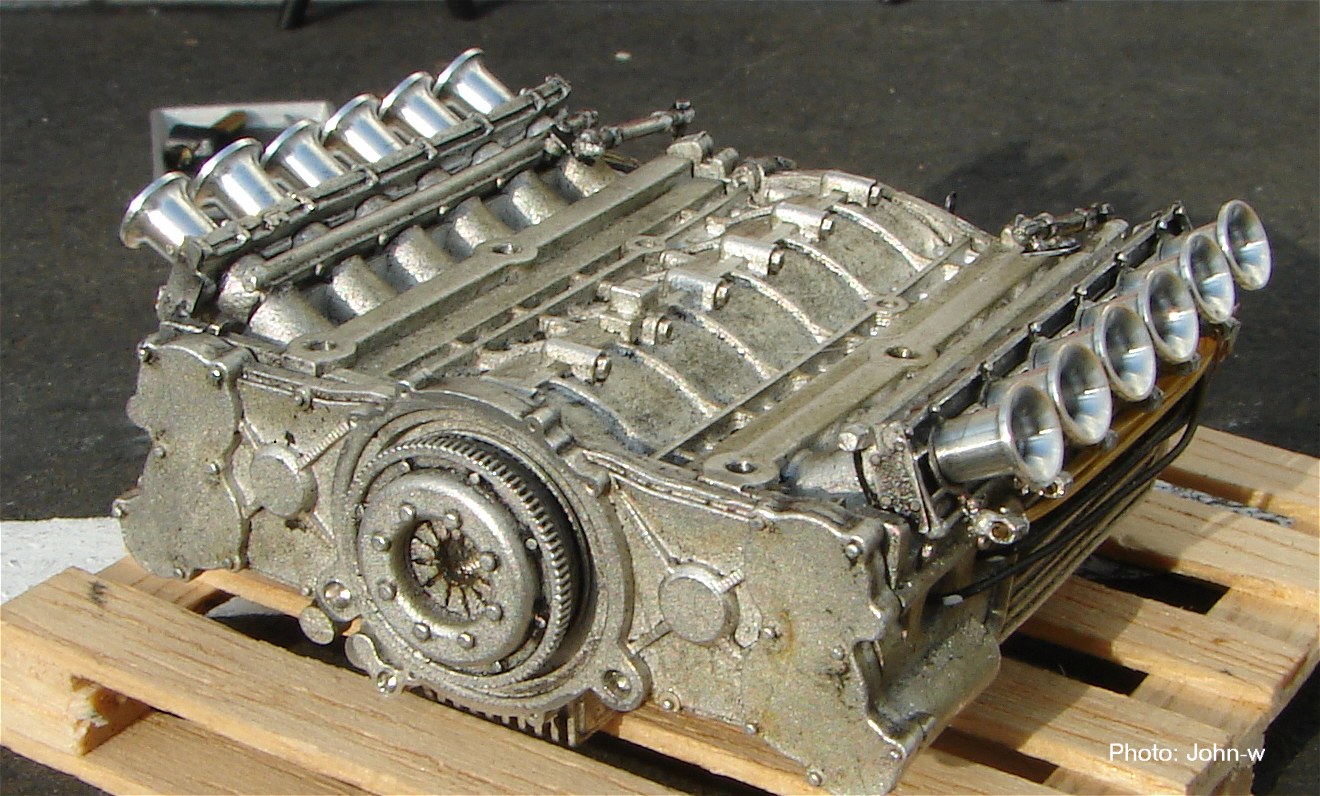
1970 Ferrari 312B 3-litre flat-12: When everybody and his dog wrote off Mauro Forghieri, Ferrari race development engineer, when in 1968 and 1969 Ferrari had bad days and netted only a single Grand Prix, his research office in Modena manned by two young engineers, Ferrari (no relation) and Caliri, an aerodynamicist, was hard at work on a new model. And return Forghieri did, with the design from a clean sheet of paper of an all new Ferrari car and engine. It remained a 12, upholding prancing horse tradition, but a flat-opposed 12. In this Ferrari had a minor tradition. In 1965 a 1.5-litre flat-12 Ferrari competed in GP racing, but was denied victories. Another flat-12 Ferrari of 2-litres with 4-valves per cylinder swept the board in the 1969 European hillclimb championship.
Early in 1969 the new 312B took shape on Forghieri’s drawing board. Its bore and stroke were 78.5mm x 51.5mm for 2991cc. The short stroke helped keep the flat engine compact and held the 312B’s weight to 144kg. Forghieri innovated boldly in the 312B’s bottom end. Its 6-throw crankshaft, was conventional enough. But after tests on the 2-litre hill-climb engine proved its feasibility, the crank was carried in only 4-main bearings. Roller bearings were used, which required a build-up crankshaft for the assembly of the 2-centre main bearings, but blow-ups in early testing led to a switch to a one-piece crankshaft and plain bearings at the 2-centre mains, with rollers only at the ends.
The crank was machined from a billet of steel alloyed with manganese and aluminum to obtain a suitable surface for use with the roller bearings. After the change to a one-piece crankshaft, failures continued. A study of the crank’s resonant characteristics showed that the attached mass of flywheel brought the torsional movements of largest amplitude to a weak point on the crankshaft. Pirelli technicians helped Forghieri develop a rubber coupling between the crank and flywheel that shifted the largest amplitude to a portion of the crank that could tolerate it.
Forghieri had favored roller bearings throughout the bottom end because they require less oil, which meant the less of it would be splashing around inside the crankcase, wasting power on oil foaming and heating. Rollers for the rods were tried but given up as too difficult and complicated and replaced by conventional bearing shells on 36mm journals. Both titanium and steel con-rods 110mm long were used, those of steel being pared to the minimum along the ‘I’-section shank. Fitted with 3-rings, pistons were fully-skirted. The inner surface of the crankcase was shaped closely to the radius swept by the rod big-ends.
The Ferrari engine benefited from having constant crankcase volume, free from compression losses, in each group of 4-cylinders between the main bearing panels. Crankcase oil was collected in a deep finned magnesium sump. Outside it, along the left side of the sump, was a row of 3-oil scavenge pumps driven in series from a gear train at the front of the engine. Each pump sucked oil from its own section of the sump. The cylinder heads had mini-dry-sump system of their own with a small scavenge pump at the rear driven by the exhaust camshaft.
At the rear of a battery of scavenge pumps was the oil pressure pump, whose main output was piped to the front of the engine where it entered the nose of the crankshaft, all the oil for the rod bearings flowed through a gallery drilled from one end of the crank to the other. When oil from the rod bearings was flung off the spinning crank, some of it was captured by a gutter that ran along the upper surface of the crankcase, cast into the left-hand half. From the gutter, passages were drilled down to the 2-roller bearings at the ends of the crank. Originally the this passage was also used to lubricate the 2-centre mains, but when these were changed to plain bearings a separate oil gallery was added, along the left side of the engine, to supply them with pressured oil.
At the front of the 312B, driven by a pair of step-down spur gears was a compact accessory box full of bevel gears. One bevel drove the water pump, placed horizontally under the box and almost hidden by it. water entered the pump at the bottom and was spun out through 2-exit ports into passages cast into the sump. A gallery running the length of the block, just bellow each cylinder head parting line, admitted coolant to the heads close to the seats of the exhaust valves. Inside each head the water rose and exited at the front of the head through a gallery above the inlet valve seat.
In addition to serving as the main rear structure of the 312B, the aluminum crankcase was divided into 2-blocks of 6-cylinders. A vertical split down the middle separated it into equal parts and formed the parting line for the 4-main bearings. The bulkheads that supported the mains were massive. From the top to bottom of each bulkhead no less than 6-studs knitted the blocks together laterally – 3 above and 3 bellow each main bearing.
A radical departure from the Italian tradition of wet cylinder liners was made by the 312B, which had integrally cast cylinders. These made the block stronger at a price of additional labour for the foundry. The cylinder running surface was provided by an inserted cast-iron dry liner which was surrounded at its top by water jacket next to a shoulder against which the liner was clamped 28mm bellow the head parting. 14-studs retained each cylinder head, and also an aluminum casting with which the cam and tapped carriers were integral.
The twin overhead camshafts were driven by a train of ruggedly mounted spur gears which were spread across the output (rear) end of the block. Forghieri settled on this instead of the more space consuming cogged rubber belt he’d considered at one stage of the design. Spaced closely together, the camshafts operated 4-valves per cylinder through small-diameter piston-type tappets. Experimentally Forghieri tried included angles between the inlet and exhaust valves that varied from 20 degrees to 27 degrees and found relatively little difference in output over that range. He settled on a 20 degree included angle.
The valves were closed by single coil springs. Fabricated in Germany of Swedish steel valve sizes were 31mm inlets and 27mm exhausts. The shallow valve inclination facilitated a straight and thus efficient inlet port, in which the injector nozzles were downstream of the slide throttles. It also created smooth, compact and efficient combustion chambers – not easy to obtain in a large bore high-compression engine. The valve heads were only slightly recessed into the surface of the cylinder head, and shallow cut-outs in the flat piston tops provided clearance for the valves at TDC. The single central spark-plug was mounted within a boss that protruded slightly downward into the chamber to place the plug gap close to the centre of the chamber volume.
Considering the novelty of this engine, remarkably few changes were needed during its first full season on track. The casting at the front that housed the accessory drive gears was redesigned to provide a more convenient connection to the crankshaft oil supply hose. New camshaft covers had handier exits for the oil scavenged from the cylinder heads. At the front , the transverse throttle shaft was given an overhung bearing where it was linked to the Lucas fuel injection metering unit, and a bevel drive from the right-hand inlet camshaft replaced a cogged-belt connection to the Lucas fuel pressure pump.
When first raced in 1970 output was 455bhp@11500rpm. Most engines were producing 460bhp@11600rpm by mid-season, though 11000rpm was considered the upper limit for race reliability. By 1971 the GP engine was rated at 475bhp@12000rpm. By its final season in 1980 the 312B cylinder dimensions had been amended to 80mm x 49.6mm for 2992cc, and its output had risen to 515bhp@12400rpm. In 1971 this flat-12 also made an appearance in the 312P roadster build to compete in the sports car championship with 3-litre limit, with 11.5:1 compression ratio, its engine was rated at 450bhp@10800rpm.
Specifications:
Cylinders F12.
Bore 78.5mm.
Stroke 51.5mm.
Stroke/bore ratio 0.66:1.
Capacity 2991cc.
Compression ratio 11.5:1.
Con-rod length 110mm.
Rod/crank radius ratio 4.3:1.
Main bearing journal 50mm.
Rod journal 36mm.
Inlet valve 31mm.
Exhaust valve 27mm.
Inlet pressure 1.0 Atm.
Engine weight 144kg.
Peak power 460bhp@11600rpm.
Piston speed corrected 24.2 m/s.
Engine bhp/litre 153.8bhp/litre.
Engine weight per bhp 0.31kg/bhp.
Many media publications and individuals including (grandprixhistory,org) wrongly assume and describes the FERRARI 312B design as being a horizontally opposed “boxer” design. Which of course it was not. They wrongly assume that the letter “B” stands for “boxer”- a German expression for opposed cylinder engine. The FERRARI 312B was in fact a 180 degree ‘V’ engine.
if the 312B (refreshing after Ferrari's unimpressive F1 V12s) was correctly called a 180 degree V12 then .....
so was the engine of the Porsche 917, and 'flat 12's by Cisitalia 'flat and Alfa Romeo (tipo 160 and prewar 512) ... etc
ie every flat 12 ever made should be called a 180 deg V12
(a 12 will give even firing whether 60 deg, 120 deg, or 180 deg)
it's a shame people couldn't just call them flat 12 (or flat 6 or flat 4 etc as appropriate)
but didn't Ferrari make road cars eg the 1971 365 GT/BB then the BB512 that they called Berlinetta Boxer (BB) ?
shortly after the 312B there was a 2 litre Tecno flat 8 with 3 main bearings - maybe we should call it a 180 deg V8
(irrelevant but amusing - the GMC V8 (for commonality with their V6 & 'double 6' V12) had 8 crank throws)
it's a shame that no-one took a 4.5 litre Offenhauser-powered car to the F1 GPs
(the Americans having retained the 1938 GP engine rules which were the basis of F1)
the Offenhauser could have won some GPs in 1948 and 1949
(R&T said its race power in 1952 was 320 hp @ 5500 rpm)
the (UK) Board of Trade banned imports of race cars or engines except by those in motor research eg Vandervell
the Ferrari 375 was expected to dominate the 1952 F1 season - 4 entered the Indy 500 but were very unsuccessful