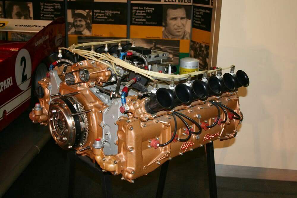
1975 Alfa Romeo 115-12 3-litre FLAT-12
1975 Alfa Romeo 115-12 3-litre FLAT-12. Alfa Romeo sports-prototype racing GT category successes in the 1960-1964 lured former Alfa Romeo engineer Carlo Chiti to the fold. Encouraged by Alfa’s enthusiastic chief Giuseppe Luraghi, Chiti in 1964 founded a new company near Milan, Autodelta, to develop and race cars for Alfa Romeo. Engineering for Autodelta’s projects was carried out by Chiti’s team with the blessing of Alfa engineers Orazio Satta and Giuseppi Busso.
Taking the sports-car racing category seriously, Chiti decided to build a completely new car for it, the type 33TT3. This had a tubular space frame, and its gearbox was located between the engine and the final drive. Although this first raced with a 3-litre V8 engine, a new flat-12 was being built to suit it. Thus-equipped the car became the 33TT12. First raced in 1973, by 1974 the new car was mature enough to win the 1000km’s of Monza. In 1975 the 33TT12 won the world championship of makes for Alfa Romeo. For 1977 Autodelta build a new chassis, the 33SC12, with aluminum monocoque frame. This was faster qualifier and winner of all 8-rounds of the makes world championship against modest opposition.
The Alfa flat-12 was rated at 470bhp@11000rpm at its launch in 1973, and at 490bhp@11500rpm in 1974 with 240lb/ft of torque@9000rpm. By mid-1975 with a compression ratio of 11:1, its peak output was a very impressive 526bhp@12000rpm with a power curve giving in excess of 400bhp from 9000rpm upwards. These were heady figures indeed in 1975, the year when another Italian flat-12 powered Niki Lauda to a Formula 1 world championship.
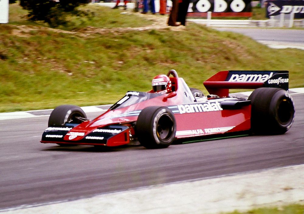
Indeed no one at that time was claiming a higher output from a 3-litre un-supercharged engine. Bernie Ecclestone, then owner of Brabham, negotiated with Alfa Romeo to gain exclusive use of their engine for his team from 1976. The flat-12 was raced by Brabham from 1976 to 1978 in cars designed by Gordon Murray. The first year was difficult, the second less so and in the third a number of good placings were achieved plus 2-victories for Niki Lauda at Sweden's Andersdorp and Italy's Monza. The Andersdorp victory was with the controversial 'fancar' Brabham, which used a 'cooling' blower to add downforce, the concept was banned after the race.
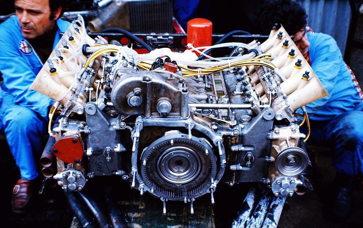
In designing the Brabham, Murray was challenged by the flat-12’s size and weight. It was, first of all, massive. Its weight in endurance-racing form was a substantial 178kg, some 10% more than most GP engines of the same displacement. In its GP version the 12’s weight was reduced to 175kg. It was also wide, wider than the flat-12 engine fielded by Ferrari. One reason for this was its longer stroke. Its cylinder dimensions were 77mm x 53.6mm for 2995cc, the Ferrari stroke was only 49.6mm in its final form. Another reason was that its inverted-cup-type cam followers were placed above its twin coil valve springs instead of being made large enough in diameter to shroud the valve springs. This effected a vital saving of mass in the follower, helping the engine reach its high speeds, but at a cost in engine weight and width.
It had 4-valves per cylinder, measuring 33mm for the inlets and 28mm for the exhaust. The endurance racing engines had 30mm inlets and 25.5mm exhaust valves. The valves were inclined at a narrow included angle of 27 degrees, 13 degrees for the inlets and 14 degrees for the exhaust. And had very long stems above the springs to allow the inlet port to enter the cylinder at the shallow angle of 38 degrees to its centerline. Previously the valves were alloy steel, in GP tune the Alfa engine used valves made of titanium. Attached by long studs to each cylinder head was an aluminum cam and tappet carrier whose bottom parting line was near the tops of the coil springs. Down the centre of the head the studs were long enough to serve also to retain the magnesium cam cover.
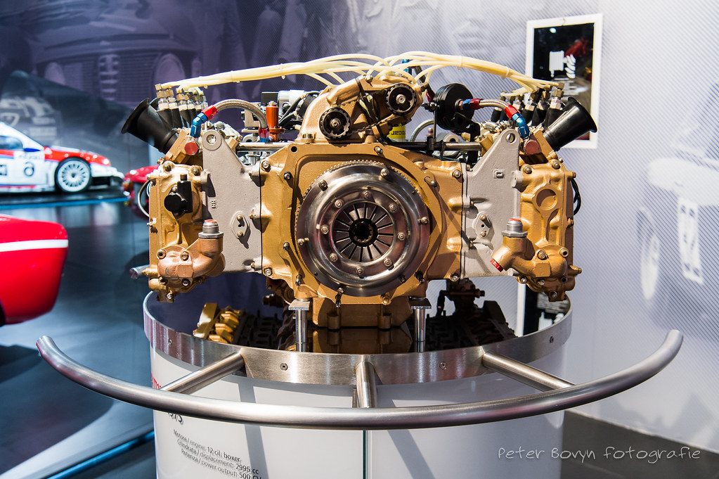
Within the carrier the 7-bearings for each camshaft were held in place by individual caps, each with its own pair of retaining studs. The spur-gear train to the camshafts was located at the rear of the engine, adjacent to the clutch. A gear train upwards drove the distributor for the Marelli Dinoplex ignition system, which sparked one plug per cylinder.
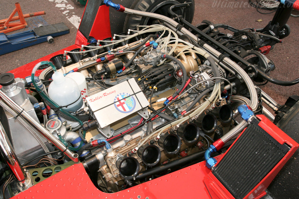
This was on the left side, while the distributor for the Lucas fuel injection was on the right. The injection fed nozzles that were set into the sides of the short ram pipes, just above the slide throttle.
A lighter-duty spur gear at the nose of the crankshaft drove the engine’s pumps, a single central water pump served both banks of the flat-12 heads. Coolant was drawn off through a head –length passage just above the inlet ports. All the engine’s main castings were of aluminum. Individual wet cylinder liners were fitted in a construction not unlike that of the flat-12 Ferrari, the top two-fifths of the liner was of a heavier section which at its bottom, was clamped by the head against a ledge in the block’s bore. Only to that depth was the liner surrounded by water, its lower three fifths were pressed into the aluminum block. Although in the sports-racers the liners were iron, in the GP engine they were made of aluminum with chromed bores to reduce the engine’s weight.
The Alfa engine was a typical flat-12 in that it carried side-by-side con-rods on a 6-throw crankshaft. Although the endurance-racing version had 7-main bearings, the F1 edition followed the example of Ferrari 312B in having only 4-main bearings. All were plain trimetal bearings except for the rear main which was a ball bearing. This allowed the use of larger counterbalance masses in the GP engine where the eliminated main bearings had previously been. To augment the crank’s counterbalance mass in a compact crankcase, the peripheries of the counterbalances were fitted with bolted-on crescents-shaped tungsten-alloy masses.
Titanium con-rods 112mm long from centre to centre had robust ‘I’-section shanks. The caps were retained by nuts on 2-studs set into the rods. Aluminum pistons were slipper-type in the GP engine. They carried 2-compression rings and 1-oil ring above the gudgeon pin.
The main-bearing supports were integral with the webs of the split 2-piece aluminum block-crankcase, there were no separate main bearing caps. The slice down the middle of the crankcase separating the 2-halves wasn’t made vertically as it was in every other such engine, it was on a plane slightly counter-clockwise from the vertical, as viewed from the front of the engine, skewed at about 7 degrees. Studs across the top and bottom of the crankcase held its halves together.
A long opening in the underside of the crankcase was closed off by a shallow cast magnesium sump. In the endurance-racing engine this was scavenged by a battery of 3-double-sided gear-type oil pumps bolted to the side of the sump, sucking oil from 6-screened drains. For the F1 application the pumps were moved to the front in order to lower the engine’s centre of gravity. Separate scavenge pumps for each cylinder head drew oil from passages within each tappet carrier and cover. Chiti had not forgotten his oil-scavenging experience with the 120F Ferrari V6.
In its Formula 1 form the flat-12 was designated the type 115-12. Its power output continued to be rated at over 520bhp in its GP trim, for which the main effort was not to get more power but to shed more weight. Another goal was to broaden the engine power band. Like the Brabham of the same year, the type 179 and its successor of 1982 the T182 was powered by a version of the 115-12 engine with a 60 degree bank angle version instead of a 180 degree vee. Using essentially the same heads as the flat-12. This was created to make more room for the ground-effects venturis that were just coming into use.
Specifications:
Cylinders F12.
Bore 77mm.
Stroke 53.6mm.
Stroke/bore ratio 0.70:1.
Capacity 2995cc.
Compression ratio 11:1.
Con-rod length 112mm.
Rod/crank radius ratio 4.2:1.
Inlet valve 33mm.
Exhaust valve 28mm.
Inlet pressure 1.0Atm.
Engine weight 175kg.
Peak power 526bhp@12000rpm.
Piston speed corrected 25.3m/s.
Engine bhp per litre 175.6bhp/litre.
Engine weight per bhp 0.33kg/bhp.
- Login or Register
No account yet? Sign up