- Login or Register
No account yet? Sign up


Yes, max downforce is not the only target. I had to accept compromises with cooling, rear wing feeding, mesh requirements and also the 10mm rule.machin wrote: ↑09 Oct 2019, 13:47Interesting; thanks for the slice... I was trying to find an old picture from one of Variante's previous cars, but I can't find one... and I don't suppose he would care to divulge one now?
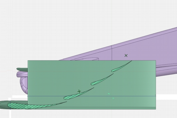
...But actually it is interesting to note another difference between your wings: Varinate's flap elements all increase step by step in angle of attack (relative to the ground), whereas yours are much more similar to eachother (the upper element does have a higher angle of attack than the first flap, but Variante's upper element is almost vertical; I'll re-post the image before, which is just an extract from the official images, so he shouldn't complain too much )
http://www.competition-car-engineering. ... arison.png
In this respect Variante's wing is more like what I would expect to see, based on real F1 wings... Again, are you (Matteo) using flatter AoA mainly just for flow control purposes, rather than trying to extract the maximum from the wing?
Yes, max downforce is not the only target. I had to accept compromises with cooling, rear wing feeding, mesh requirements, 10mm rule and also an easy and consistent computational convergence, avoiding critical flow conditions.machin wrote: ↑09 Oct 2019, 13:47Interesting; thanks for the slice... I was trying to find an old picture from one of Variante's previous cars, but I can't find one... and I don't suppose he would care to divulge one now?
...But actually it is interesting to note another difference between your wings: Varinate's flap elements all increase step by step in angle of attack (relative to the ground), whereas yours are much more similar to eachother (the upper element does have a higher angle of attack than the first flap, but Variante's upper element is almost vertical; I'll re-post the image before, which is just an extract from the official images, so he shouldn't complain too much )
http://www.competition-car-engineering. ... arison.png
In this respect Variante's wing is more like what I would expect to see, based on real F1 wings... Again, are you (Matteo) using flatter AoA mainly just for flow control purposes, rather than trying to extract the maximum from the wing?

Out of interest what DF & L/D are you getting?
Please Variante, don't look at the numbers below
Code: Select all
Force Coefficients averaged wing_front - Cd: 0.1631827136, Cl: -1.0791803803, Cl/Cd: -6.6133253722, Cl(f): -3.3408536839, Cl(r): 2.2616733034, CoP: -Consider that I renounced to a bit of downforce (gaining a bit of drag too) from the front wing to have a significant outwash that helps my with downforce provided by the central part of the floor (much more useful because it does not affect cooling and balance).
Congratulations for the excellent quality of the modeling. I also used three sections only at first, in order to have less paramter to be optimized. 4 o 5 section give advantages but not significant. On the contrary I only use a small strake under the front wing, just because I need a small vortex running near the wheels (internally).jjn9128 wrote: ↑09 Oct 2019, 14:17Again to even the score.
https://pz1vqw.by.files.1drv.com/y4m9Oq ... pmode=none
https://pz1mqw.by.files.1drv.com/y4mLYM ... pmode=none
The wings are about the only thing I think I'm doing well on


Interesting that with smaller FW I got similar numbers after Singapore
That's what I wanted also to mention that general idea behind multi-element wing is that combined chord line is more cambered compared to less elements wing, but in CAEdevice's one it looks indeed like diffuser, and upper part of the leading edge of 3rd profile looks bit weird for me.
Also to mention that some regulations in some series were quite strict allowed volume for profiles, so they tried to find maximum out of such configuration. Also there were main profiles with trimmed trailing edge so flap could fit into that trim, very similar to what you can see on planes' wings.machin wrote: ↑09 Oct 2019, 13:47...But actually it is interesting to note another difference between your wings: Varinate's flap elements all increase step by step in angle of attack (relative to the ground), whereas yours are much more similar to eachother (the upper element does have a higher angle of attack than the first flap, but Variante's upper element is almost vertical; I'll re-post the image before, which is just an extract from the official images, so he shouldn't complain too much )
Image
So the underside of the wing follows an arc (from a circle)? I would never ever start like that. Why would this arc be the best geometry? Do they stretch the geometry after they are done? To me it would more sense to create something like an ellipse and use an optimization algorithm together with CFD to optimize the two parameters of said ellipse. Circles are cool, but they are just a random shape.variante wrote: ↑09 Oct 2019, 17:07Hell, i'm already lagging behind CAEdevice, so i'm not giving away the schematics of my FW
But i can show you how a professional does it:
https://i.imgur.com/OOYPUPI.jpg
(taken from a SimScale webinar).
The way i make my wings is not too different. I find it important to decide a guide line for the low pressure side. It's an arc of circumference in the image here, which i also use for lower DF (and lower upwash) applications; for high DF, i use an arc of ellipse (as Machin essentially noticed).
The aerofoils arrangement, thickness and style from jjn9128 are extremely similar to mine.
CAEdevice's wing shape reminds me of a diffuser!