[MVRC] CCE GP001

Post here information about your own engineering projects, including but not limited to building your own car or designing a virtual car through CAD.
User avatar
LVDH
44
Joined: 31 Mar 2015, 14:23

Re: [MVRC] CCE GP001

Post

machin wrote:
08 Oct 2019, 21:51
So... cutting the holes in the top of the sidepod made a big difference... and the big tall plumes now emanating from them show just how much of a restriction was caused by the original tight "slalom" route the air had to take through the heat exchangers and then through the duct; with the holes on top of the sidepod the air now takes a much smoother flow, and that has resulted in a doubling of the flow!

...On the downside these plumes are now seriously affecting rear wing performance!

http://www.competition-car-engineering. ... ow_rd3.png

So, something of a compromise between the two would seem to be a good idea.... :)
The image is pretty cool, because it clearly shows how additional cooling can be detrimental to down force. In this case probably also for balance.

User avatar
machin
162
Joined: 25 Nov 2008, 14:45

Re: [MVRC] CCE GP001

Post

hollus wrote:
09 Oct 2019, 06:38
It is awesome when you MVRC guys publish these changes in the open. Very thought inspiring! Thanks!
As the other guys are busy trying to win the challenge they're not quite so open, but sometimes a little prodding opens them up... as I'm on the admin side I have nothing to lose... :)
Any reason why those plumes from the top of the sidepods cannot be directed outwards as well as upwards, thus clearing the rear wing and maybe, just maybe, hitting the rear tires?
Here's my thinking why I put the holes on top.

In Round 1 I was under-powered due to lack of cooling flow.

Round 2 was the same arrangement with a bigger inlet and a bigger heat exchanger -achieved by tilting it more forward and making it longer, hence more frontal area. This second round car had less flow!

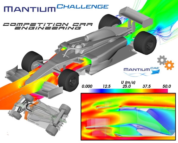
So by a process of deduction it seems that the driving factor was not the Heat Exchanger size, nor the sidepod opening area, but in fact the tight "S" shaped flow path through the heat exchanger itself, as depicted in the first image below. To solve this the simplest solution was to cut the top off the sidepod and use more upright heat exchangers letting the air follow a much less restrictive (Bigger "S") flow path... (lower image).

It has worked far better than i expected (in terms of cooling flow)! :P

Image

Cutting the holes in the side of the sidepod would've actually added an additional tight bend in the flow path... unless I had rearranged the heat exchangers so they are angled in the horizontal plane, rather than the vertical plane... but that's currently not allowed in the rules....

As others have suggested; adding some guide fins/louvres on top of the holes will be the next step: I now have lots of excess cooling flow to play with!
COMPETITION CAR ENGINEERING -Home of VIRTUAL STOPWATCH

User avatar
machin
162
Joined: 25 Nov 2008, 14:45

Re: [MVRC] CCE GP001

Post

Whilst we wait for round 4 of the MVRC (this weekend), I thought I would post the result of adding an array of guide fins in the flow downstream of the sidepod heat exchangers for flow management purposes.

First here's the car I submitted:-

Image

...and here's the new flow regime coming out of the sidepods:-

Image

So now the flow doesn't affect the rear wing quite so much... and actually it didn't reduce the flow through the heat exchangers either.... so there's still scope for further improvement by trading flow rate for flow direction...

I also had a go at using what I will call "Variante's Circle method" for designing the wing profiles, in which the lower surfaces of the aerofoil cascade follows a circular path. Here's the front wing, it achieved about 50% more downforce than my previous wing design:-

Image

....But the car is still a long way off the front of the field! :oops: :lol:
COMPETITION CAR ENGINEERING -Home of VIRTUAL STOPWATCH

User avatar
CAEdevice
45
Joined: 09 Jan 2014, 15:33
Location: Erba, Italy
Contact:

Re: [MVRC] CCE GP001

Post

Your car improved very much during the season! It would deserve an extensive article, but I know that time is never enough (by the way: there are articles on specialised magazines that are not as interesting as this thread about your MVRC car).

If I could make a couple of changes on your design I would work on bargeboards (I would definetly chose outwash bargeborads) and cooling (I am sure that it is not necessary to disturb the flow above the sidepods).

User avatar
machin
162
Joined: 25 Nov 2008, 14:45

Re: [MVRC] CCE GP001

Post

CAEdevice wrote:
31 Oct 2019, 11:17

If I could make a couple of changes on your design I would work on bargeboards (I would definetly chose outwash bargeborads) and cooling (I am sure that it is not necessary to disturb the flow above the sidepods).
yes, your car achieves good cooling without the need for the hole/louvres/guide vanes on top of the sidepods.... when I made the change with the holes on top of the sidepods I also changed the angle of the radiators so they are more upright; so it is not possible for me to know for sure which change actually made the biggest difference...which just goes to prove the old andage that you should only change one thing at a time.... but I am a bit constrained with computing power, and to be honest more importantly, time; so I've only made one update (untested) between each race. Certainly from the latest results I know that my car achieves "too much" flow through the heat exchangers, so there clearly must be a benefit to be had from trading off some flow rate for more rear downforce.....

I think everyone would prefer to read some information on the design iterations of your car :-)
Last edited by machin on 31 Oct 2019, 14:50, edited 1 time in total.
COMPETITION CAR ENGINEERING -Home of VIRTUAL STOPWATCH

User avatar
variante
131
Joined: 09 Apr 2012, 11:36
Location: Monza

Re: [MVRC] CCE GP001

Post

machin wrote:
30 Oct 2019, 23:22
I also had a go at using what I will call "Variante's Circle method" for designing the wing profiles, in which the lower surfaces of the aerofoil cascade follows a circular path. Here's the front wing, it achieved about 50% more downforce than my previous wing design:-
Hahah nice! Next time you can also try a more aggressive path than a circle (as long as you have enough rear downforce).
The aerofoils are nice and well coupled. Did you get inspiration from one of the MVRC competitors?

User avatar
LVDH
44
Joined: 31 Mar 2015, 14:23

Re: [MVRC] CCE GP001

Post

I actually also like his front wing profile design. This circle approach seems to have more merit than I thought. And 50% additional downforce is proof of that.

User avatar
machin
162
Joined: 25 Nov 2008, 14:45

Re: [MVRC] CCE GP001

Post

variante wrote:
31 Oct 2019, 14:49
Did you get inspiration from one of the MVRC competitors?
For sure the design is heavily influenced by numerous other competitors, but looking at the details everyones wing elements are really quite different from eachother, but yet all of a very high performance. As you can see from the overall design there is no "outwash" intent taken into account with my wing... first I wanted to see if I could get a design that simply produced a decent amount of downforce (previous designs didn't work on the low pressure side: I just got separation very early on).... But I think it is still probably 50% down on the level of downforce that yours and others front wings achieve.

But you are right; my problem to try and resovle for next race is rear downforce, since COP is still way too far forward.
COMPETITION CAR ENGINEERING -Home of VIRTUAL STOPWATCH


User avatar
CAEdevice
45
Joined: 09 Jan 2014, 15:33
Location: Erba, Italy
Contact:

Re: [MVRC] CCE GP001

Post

machin wrote:
31 Oct 2019, 14:47
yes, your car achieves good cooling without the need for the hole/louvres/guide vanes on top of the sidepods.... when I made the change with the holes on top of the sidepods I also changed the angle of the radiators so they are more upright; so it is not possible for me to know for sure which change actually made the biggest difference...which just goes to prove the old andage that you should only change one thing at a time.... but I am a bit constrained with computing power, and to be honest more importantly, time; so I've only made one update (untested) between each race. Certainly from the latest results I know that my car achieves "too much" flow through the heat exchangers, so there clearly must be a benefit to be had from trading off some flow rate for more rear downforce.....
I agree, but I noticed that you don't have any guide for the flow in front of the cooling inlets, but, you are right, I should show more of my car, despite, among the teams that are fighting for the challenge CAEdevice and Variante are the ones the showed more... anyway, here is a detail from my car where you can see the effects of the bargeborads on the cooling flow:

Image
machin wrote:
31 Oct 2019, 14:47
I think everyone would prefer to read some information on the design iterations of your car :-)
I also think that someone could be interested in my car, I can publish more images in exchange for the recipe of a Danish cold buttermilk soup

User avatar
LVDH
44
Joined: 31 Mar 2015, 14:23

Re: [MVRC] CCE GP001

Post

I think that CAEdevice close-up of the cooling inlet is super cool. He could close the inlet up a lot by moving the lower edge up and it would not at all reduce cooling flow. This shows why some cars have so small openings while others can open up more and nothing happens.

User avatar
CAEdevice
45
Joined: 09 Jan 2014, 15:33
Location: Erba, Italy
Contact:

Re: [MVRC] CCE GP001

Post

LVDH wrote:
31 Oct 2019, 17:35
I think that CAEdevice close-up of the cooling inlet is super cool. He could close the inlet up a lot by moving the lower edge up and it would not at all reduce cooling flow. This shows why some cars have so small openings while others can open up more and nothing happens.
Also the front wing design is very important, expecially the exit angle of the flow, together with the use of the negative pressure in the volume below the rear wing.

I did not need many iterations (I launched less than 30 simulations from the rules release months ago), but I admit I take advantage from the similarities of the cooling layout of my 2019 Formula M car compared to previous year LMPx car. By the way: Variante cooling ducts are not so different (except for the HX placement) from the concept he used in 2018.

User avatar
Koldskaal
24
Joined: 14 May 2019, 10:02
Location: Denmark

Re: [MVRC] CCE GP001

Post

CAEdevice wrote:
31 Oct 2019, 15:57
... despite, among the teams that are fighting for the challenge CAEdevice and Variante are the ones the showed more... anyway, here is a detail from my car where you can see the effects of the bargeborads on the cooling flow:
machin wrote:
31 Oct 2019, 14:47
I think everyone would prefer to read some information on the design iterations of your car :-)
I also think that someone could be interested in my car, I can publish more images in exchange for the recipe of a Danish cold buttermilk soup
I almost feel like you are calling me out there :D . Anyway these are some of my thoughts regarding sidepods.
I had one goal in particular in mind when designing my latest sidepods. I wanted good clean air to reach the rear of the car, specifically the middle part of the diffuser and the rear wing. This meant that putting the exhaust down by the floor as WBR has done was a no-go. I also wanted to avoid ducting the air all the way to the rear, to give myself some more room to play with. This comes with the cost of having to ensure that the exhaust doesnt mess with the rear wing. As it has been demonstrated in this thread. So i finally decided to direct the exhaust outwards. That the exhaust now mostly hits the rear tyre was more or less incidental.
Image
I suspect that this doesnt decrease drag as much as one might think. In many cases the front tyre wake will probably end up hitting the rear tyre. Anyway you can compare your own numbers to mine. The maximum CP on the rear tyre is around 0.5
MVRC - Koldskaal, name: Christian

User avatar
CAEdevice
45
Joined: 09 Jan 2014, 15:33
Location: Erba, Italy
Contact:

Re: [MVRC] CCE GP001

Post

Thanks for sharing your streamlines! I appreciate it more than the recipe :)

I noticed that we have a different way to manage the cooling outlets, but a common strategy about the inlets. We but feed the hxs with the flow coming from (mostly) below the front wing. On the contrary CCE car uses flow from above the wing. I think that has effects on the energy that reaches the cooling inlets.

User avatar
Koldskaal
24
Joined: 14 May 2019, 10:02
Location: Denmark

Re: [MVRC] CCE GP001

Post

CAEdevice wrote:
31 Oct 2019, 23:46
Thanks for sharing your streamlines! I appreciate it more than the recipe :)

I noticed that we have a different way to manage the cooling outlets, but a common strategy about the inlets. We but feed the hxs with the flow coming from (mostly) below the front wing. On the contrary CCE car uses flow from above the wing. I think that has effects on the energy that reaches the cooling inlets.
I think that it is less of a strategy per se, and more just how it happend to turn out. At least in my case :D . In between Spa and Singapore I had a (perhaps) naive idea that I could fix this by creating more front wing outwash. Idea being that if the wake from the front wing would travel mostly around the outside of the front tyre, then that would allow the cooling air to travel uninterupted into the radiator.

Some energy will surely be lost on the way. On my car the front wing itself is not so much the problem, as the front wheel suspension members. They all have separation on the top and are the real cause of cptot loss of the cooling air.
if only one was allowed to angle these a couple of degrees...
MVRC - Koldskaal, name: Christian