Hello all.
In his Internet Museum at
http://www.douglas-self.com/MUSEUM/POWE ... alveIC.htm,
Douglas Self* writes:
“The Cross rotary valve: circa 1935
…
The "reaction bridge" shown in the picture at left absorbs the upward forces on the horizontal valve assembly, and is supposed to have reduced the gas forces on the actual valve. At the moment I'm not quite sure I understand how it worked.”
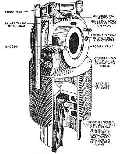
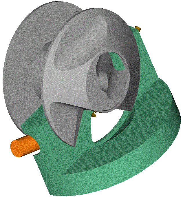
The “reaction bridge” of Cross “works” as follows:
The top half of the cylinder head is firmly secured to the crankcase by the “bridge” and the two strong pillars, i.e. the top half cylinder head and the crankcase form a rigid body.
The lower half of the cylinder head, together with the cylinder (the piece with the horizontal cooling fins) comprise another rigid body which is free to play for, say, 0.25mm (0.01”) up and down relative to the crankcase (the “spring” seal at the bottom of the cylinder pushes upwards the cylinder and the lower half of the cylinder head) .
The “horizontally” arranged cylindrical rotary valve (the typical Cross rotary valve) abuts, at its top side, on the upper half of the cylinder head.
The body comprising the cylinder and the lower half of the cylinder head abuts on the lower half of the rotary valve.
For as long as the pressure inside the cylinder (above the piston) is small (which happens during the induction cycle, during the exhaust cycle, and during most of the compression cycle, i.e. during some 70% of the total time) the cylinder with the lower half of the cylinder head are pushed upwards by a weak force; the only who prevents the cylinder with the lower half of the cylinder head to move upwards is the lower half of the rotary valve whereon they abut; and the only who supports the rotary valve from not going upwards it the upper half of the cylinder head whereon it abuts.
So, the weak force mentioned passes to the rotary valve, then to the upper half of the cylinder head and, through the pillars, to the crankcase.
During the last part of the compression cycle and during the combustion and expansion cycle, the high pressure in the cylinder translates into a heavy force onto the “cylinder and lower half of the cylinder head”, and another heavy force onto the part of the rotary valve surface whereon the high pressure gas acts through the “window” of the combustion chamber. The sum of these two heavy forces equals to the force the gas applies to the piston top. The rotary valve passes this total force to the upper half of the cylinder head whereon it abuts.
I.e. during the last part of the compression and during the combustion – expansion the rotary valve receives a strong force that deforms / flexes it, and it passes all of it to the upper half of the cylinder head.
But this heavy loading happens only during the, say, 30% of the total time. For the rest 70% of the time the rotary valve runs almost free of loads (no need for heavy preloading).
But even for the 30% during which the rotary valve undergoes strong forces, the lighter the load the engine runs, the lighter the forces on the rotary valve.
This way Cross achieved to reduce the, otherwise, necessary heavy preloading between the rotary valve on its “bearings”, improving the reliability and longevity, and reducing the specific lube consumption.
One side effect is the “side support” of the “free” / “sliding” cylinder in order to receive the thrust loads from the piston and the leaning connecting rod.
Another side effect is the significant increase of the maximum force acting on the rotary valve and its bearings: it equals to the gas pressure times the piston area.
In the conventional Cross rotary design, the force on the rotary valve and its bearings equals to the gas pressure times the “window” area.
Note: the “self-adjusting reaction bridge”, top-right in the image, may be used to reduce the “hammering” from the “oscillating cylinder”.
Quote from my last reply to J.A.W.:
“in the same “Internet-Museum”, at http://www.douglas-self.com/MUSEUM/POWE ... IC.htm#now it writes:
- “Another contemporary concept is the PatRoVa rotary valve. Like the Cross design it balances out the forces acting on the rotating valve.”
End of Quote
While the bearings of the Cross Rotary Valve receive all the gas pressure acting on the piston,
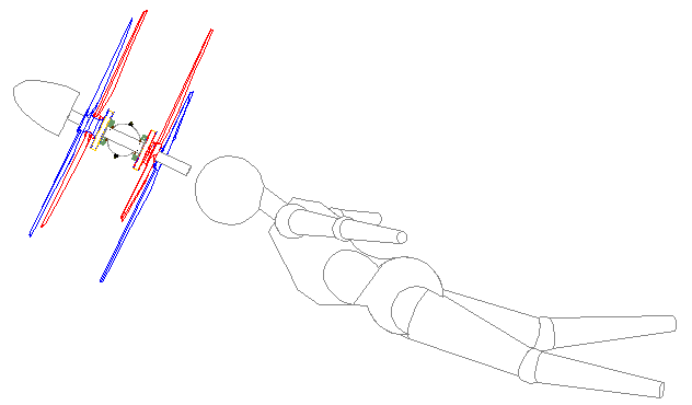
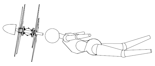
the PatRoVa rotary valve:
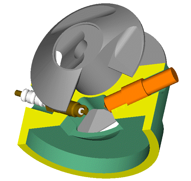
runs permanently unloaded as the following quote from
https://www.pattakon.com/pattakonPatRoVa.htm explains:
Heavy, but internally counterbalanced, loads
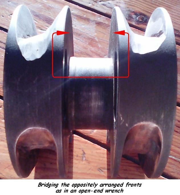
The high pressure inside the cylinder "sees", though the chamber ports, the two fronts and loads them heavily. The rotary valve receives the two strong forces. With the one force counterbalancing the other (through the body of the rotary valve), the overall "pressure" force acting on the rotary valve is from small to zero, leaving its bearings unloaded.
That is, in order to bear the heavy forces applied by the cylinder pressure on its fronts, the PatRoVa "disk rotary valve" needs not the support of a bearing and avoids, this way, both: the inevitable clearance / "play" a bearing introduces and the associated friction / wear.
What the rotary valve does need is a very strong "body" to "connect" the oppositely acting fronts; so strong that the heavy loads applied on the fronts to cause no more than an insignificant deformation of the rotary valve and thereby to keep into the required strict limits the clearance between the chamber ports and the rotary valve fronts (wherein the sealing happens).
Thanks
Manolis Pattakos