LegendaryM wrote:So the 2012 car, albeit rather late:
http://i47.tinypic.com/2z4k4uh.jpg
The new car is designed completely from scratch, which is the main reason it has taken so long. No parts are carried over from last year.
http://i45.tinypic.com/2ivjn1j.jpg
http://i47.tinypic.com/htifkg.jpg
http://i50.tinypic.com/9zx6w8.jpg
http://i48.tinypic.com/6f9g1c.jpg
Starting at the front, the front wing is a development of the one a posted in December.
http://i49.tinypic.com/2wqeh6e.jpg
Its a fairly conventional front wing, and i plan to update it soon, but its also the first front wing ive made which fully complies with 3.75 and 3.4.2, which relates to thickness in the outer section of the wing.
http://i48.tinypic.com/rkr2w8.jpg
Ive copied williams/sauber and have incorporated the brake ducts into the blade. The lower front suspension also mounts onto the wheel higher to reduce blockage from the front wing
http://i47.tinypic.com/ke7xxh.jpg
The sidepods are more conventional on this car, although i think the old ones where unrealistically small. There is a cooling exit on top of the sidepods. I plan to update the pod-vane by making it curve over the top of the sidepod like sauber.
http://i45.tinypic.com/2ihpmd5.jpg
Although the front of the floor is not in any way revolutionary, it is much more refined than previous designs I have done, especially where the leading edge meets the splitter.
http://i49.tinypic.com/2lurv9d.jpg
The airbox is conventional, with a fairly large undercut. This is the first car ive designed which fully complies with 3.8.4; a minimum 75mm radius is maintained all over the areas needed, whereas on the old car sometimes i had to reduce it to 50mm
http://i49.tinypic.com/2nbegpj.jpg
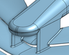
The exhaust exits as far forward as possible and quite wide out. I designed the exhaust position after doing the sidepods as i dont think compromising the airflow to the rear of the car as much as sauber is worth it. That said, the exhaust is aimed to blow towards the area inside of the rear of the tyre, although i would have to do cfd to see if it actually was.
http://i46.tinypic.com/znohsz.jpg
I have also incorporated the rear brake ducts into the blade. I have added alot of winglets onto the rear of the brake duct and the top rear suspension members are at a much more realistic angle. The drive shaft is also at a less extreme angle, although the rear of the car is still very low
http://i45.tinypic.com/ng9ctx.jpg
Here you can see how low the rear impact structure is to get the best possible flow under the beam wing, and the second cooling exit. I have incorporated the a limited ddrs into the car, though at the moment it only stalls the beam wing
http://i50.tinypic.com/2z5ordj.jpg
The rear wing is fairly conventional, ive copied ferrari style cutouts. You can also see how thick the rear wing endplate is to house the tubing for the ddrs
http://i48.tinypic.com/2h3ynop.jpg
The diffuser is not radical, but refined in my opinion. It exits partly to the side in a similar fashion to lotus. I also have a small cutout in front of the rear wheels which i also had last year. I dont have a hole for the gearbox starter hole yet ala red bull as i plan to do something involving the ddrs in this area.
The main innovation/ trick on the car is the last bit of the exhausts.
5.8.3 states that the last 100mm of the tailpipe must have a maximum diameter of 75mm and point at least 10 degrees upwards. This is problematic as I want the exhaust gases to go downwards. What' ive done is nozzle the exhaust before the last 100mm and make it horizontal so the exhaust gases should exit horizontally and not 10 degrees upwards, making it easy for the downwash effect to work
Side view:
http://i46.tinypic.com/23kfblg.jpg
Rear view:
http://i50.tinypic.com/2gxicfd.jpg
http://i45.tinypic.com/vctrpt.jpg