2 stroke thread (with occasional F1 relevance!)

All that has to do with the power train, gearbox, clutch, fuels and lubricants, etc. Generally the mechanical side of Formula One.
User avatar
PlatinumZealot
550
Joined: 12 Jun 2008, 03:45

Re: 2 stroke thread (with occasional F1 relevance!)

Post

Yes. It would be good to add a few control surfaces or titled rotors?

You device reminds of of a parachute. Except it is making lift and thrust.. And the parchute has some control of its surfaces...

The other thing your machine reminds me of is a beetle. It takes off with its big body hanging below.. I think it still controls flight with its wings.

When I imagine take off with your machine, after the pilot somehow manages to titlt the contraption forward, (by lifting his legs forward?) the center of gravity still will be below. Except some forward is developed as it tilts. When the vehicle starts to move drag will increase, thereby acting to tilt the vehicle forward more. For any non-steady changes the pilots body may swing.. Even swinging forward and tilting the rotor in the reverse direction.... Correct?


Image


Image
🖐️✌️☝️👀👌✍️🐎🏆🙏

manolis
107
Joined: 18 Mar 2014, 10:00

Re: 2 stroke thread (with occasional F1 relevance!)

Post

Hello DrAcula and thanks for your time.
.

You write:
“What if you hit something which damages both rotors on one side? which is quite likely to happen with such a setup You would have asymetrical lift which you can't recover.”


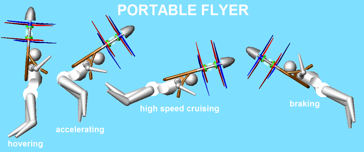
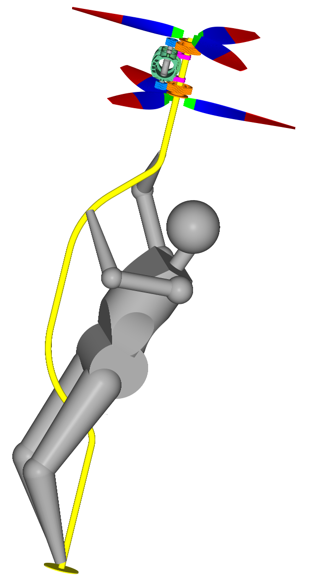
The case reminds the Broom Portable Flyer:

Image

A difference is that in the Broom version the two contra-rotating propellers are synchronized, while in the damaged Portable Flyer (where a pair of side propellers is damaged or disengaged from their engines) the pilot has to balance the two throttles (by the gas cables) in order to balance the two reaction torques and avoid this way an uncontrolled spinning (i.e. what happens when a helicopter loses its rear propeller).

Another difference is that the pilot has to bend his body to put his center of gravity close to the “working” rotation axis (i.e. under the two running contra-rotating propellers).

For the rest, the pilot can still control the flight in order to land safely.

The small distance of the two rotation axes (~550mm) makes possible the above: at normal conditions the center of gravity of the pilot is less than 300mm (1ft) offset from each rotation axis, i.e. bending his body the pilot can displace the centrer of gravity near the "working propellers" rotation axis.

Compare the above case / options with an Osprey V22 at 200m, almost standing and “prepared” for a vertical landing. If one propeller is damaged (say by hitting an obstacle) a catastrophe will follow. With one only propeller the OSPREY cannot hover.


You also write:
“Than an other thing. If i would hover in 5 or 10m hight and one engine seizes, does the other one automatically increase power or would i have to do this myself, in which case it's highly likely that i have not enough time to assess the situation and react to it before i come crushing down, with one pair of rotors still spinning which generates a chance to injure me further or even kill me.”


The tests will be at lower /safe height, initially over water (0 to 3m height), then above the ground (~1m height), away from people and vehicles.
A fall will be less risky than a fall with a motorcycle running within the traffic.
After many – many – many hours of flight at low height, the engines will show their reliability / problems.

At this height (~1m) the manual control is the simplest control.

Later we will see whether the electronic interconnection of the two engines is useful.

As for today, I am looking for a simple / reliable / affordable injection / ignition system.


You also write:
“ How heavy is somebody allowed to be, that one of your engine can keep him in the air? And i don't wanna know what other engines can achieve, what do you think your engine can do? I'm a a bit on the fat side so i don't think i'm ideal anyway, but remember, an average european male is over 80kg in underpants.”


Quote from the Device Technical Report at https://www.pattakon.com/GoFly/DTR_1.pdf

“Safety

In case of malfunction of the one engine, or in case one propeller hits an obstacle and falls apart, or in case a transmission tooth belt is broken, or . . ., the “healthy” engine-propellers-set is sufficient for a safe landing. With the one only engine running at 9,000rpm (mean piston speed: 9m/sec) and driving its two 3-blade 39’’ diameter / 28’’ pitch propellers at 3750rpm (2.4:1 reduction): the total thrust force is calculated at 250lb (115Kp), the tip speed is 195m/sec (57% of the sound velocity)”

And

“Fast take-off (at emergency, or from distant / unpopulated areas etc)

With both engines running at 9,000rpm, the upwards acceleration at a “fast take off” is more than 1g (10m/sec^2); it is like “falling towards the sky”.
Alternatively: the PORTABLE FLYER can carry two persons (the pilot and a passenger); in this case at a malfunction of the one propulsion unit, the emergency landing is not possible without opening the parachutes.”

End of Quote.

I.e. the Portable Flyer is meant to fly with a pilot of 90Kg even in case of an engine stall. With both engines running (and based on a parachute for landing in case of emergency), besides the pilot it can carry one more persons weighing 110Kg.


You also write:
“ Hanging in a 6 point harness isn't exactly comfortable, especially for men. So i hope you have a solution that wouldn't cut the blood flow to the testicals for your proposed up to 2 hours flight time.”


There is a simple and lightweight solution for this problem.
And it was tested for hours.
It is so comfortable that you can read a complete book “hanged” from a tree branch forgetting, most of the time, you are “hanged”.

Here is the basic idea:
An overalls (like those the mechanics wear) has “closed” legs whereon the feet of the “pilot” abut.

The harness remains for safety, but pilot’s weight is no longer supported by his upper legs area, but by his feet (say like standing on a floor).
If the pilot bends his legs, the weight is taken by the harness.

Image

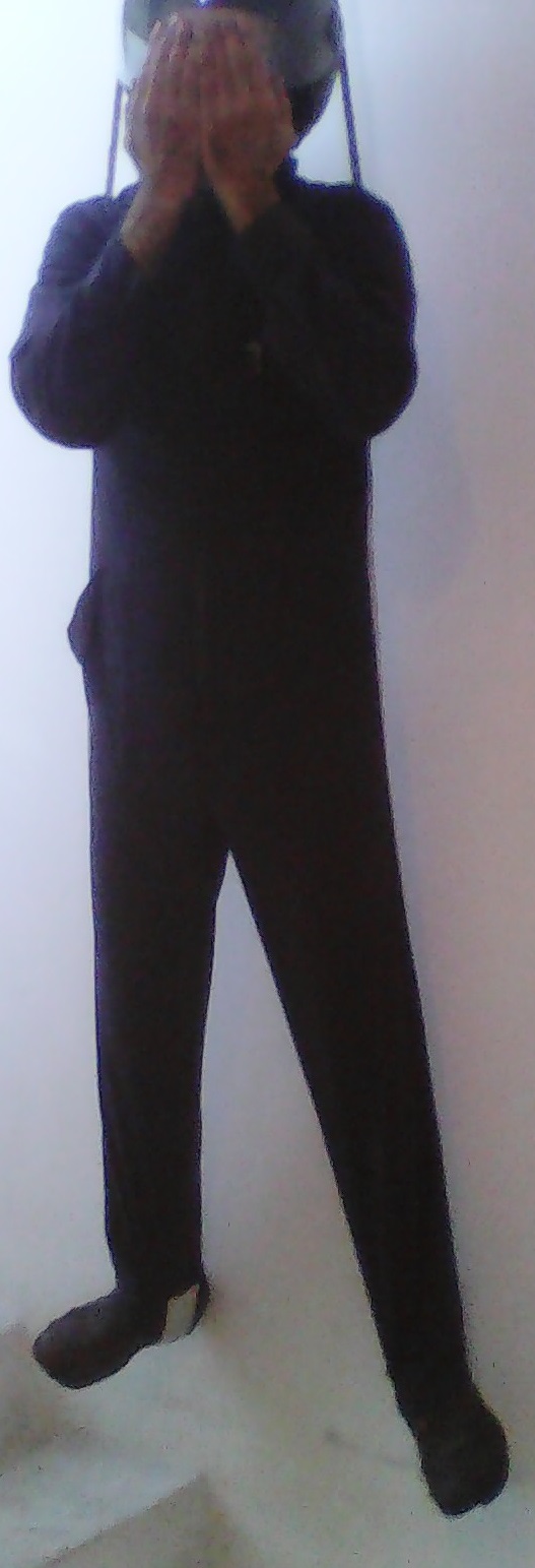
In the photo the feet of the guy are on the air.
With two ropes the overalls is hanged from the ceiling.
The armpits of the guy take no force.
Spot on the white cloth band where the right shoe of the guy stands on.
Spot on how much stretched are the trousers of the overalls.


You also write:
“ And one more thing. You came up with the "pendulum rocket fallacy". But you didn't seem to notice, that your construction has exactly the same problem. Center of lift is above center of gravity, right? So what if, i can't bring the center gravity excatly under the center of lift for what ever reason?
if you tilt your rotorsystem to compensate for that, you induce a lateral movement. So basically, your personal flyer can't properly hover if the CoG isn't exactly under the CoL. And let me guess, do you plan to store the Fuel in a backpack? What do you think where the CoG goes when you attach a 20kg backpack to the person hanging under your flyer?”


No.
There is no “center of lift”.

This is what the “Pendulum Rocket Fallacy” explains and analyses.

What there is, is a “thrust axis” (or “lift axis”).

And what the pilot does, is to displace the “thrust axis” relative to the overall center of gravity (also called “weight displacement control”, which is not correct as an expression, because the pilot cannot displace their center of gravity; what the pilot can displace is the thrust axis relative to their center of gravity).

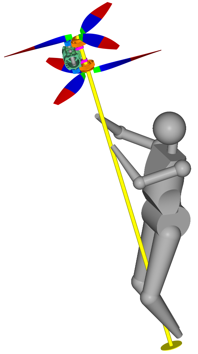
Think the case wherein the pilot and the Portable Flyer fall freely in the air. There is nothing to abut on, or to take reaction forces from. If pilot wants to change the orientation of the rotation axes of the propellers relative to their body, pilot just bends their back, or spinal cord, or pilot displaces limbs / head relative to the engines/ propellers.

So, forget the thrust point and think based on the thrust axis.

With a thrust axis the position of the center of gravity cannot be “under” or “above”.

With a thrust axis the position of the center of gravity can be either on the thrust axis, or off the thrust axis (which creates a moment that tends to change the thrust axis direction).
This moment is what the pilot exploits in order to vector the thrust to the desirable direction.

So, please re-read the “Pendulum Rocket Fallacy” article, but with intuition aside.
Just take the physical laws and apply them.


For the fuel:
The back of the pilot is not a good place to put the fuel tank (think of the high speed downstream of the propellers falling directly on a fuel tank).
Better place is around pilot’s legs, near pilots feet. During take off and landing the upper body of the pilot is not loaded by the fuel weight.


Thanks
Manolis Pattakos

manolis
107
Joined: 18 Mar 2014, 10:00

Re: 2 stroke thread (with occasional F1 relevance!)

Post

Hello PlatinumZealot

You write:
“The other thing your machine reminds me of is a beetle. It takes off with its big body hanging below.. I think it still controls flight with its wings.”

Without any wings, it is more like a dragonfly than like a beetle.

Some nice videos showing, at slow motion, dragonflies flying are at the page 181 of this discussion.


You also write:
“When I imagine take off with your machine, after the pilot somehow manages to titlt the contraption forward, (by lifting his legs forward?) the center of gravity still will be below.”

Below of what?

Having a thrust axis and not a thrust point, a “center of gravity BELOW or ABOVE” is meaningless.(Pendulum Rocket Fallacy article).

On the thrust axis and off the thrust axis is what happens.


You also write:
"Except some forward is developed as it tilts. When the vehicle starts to move drag will increase, thereby acting to tilt the vehicle forward more. For any non-steady changes the pilots body may swing.. Even swinging forward and tilting the rotor in the reverse direction.... Correct?"

The Portable Flyer pilot uses the swing to decelerate, like:

Image

Thanks
Manolis Pattakos

Rodak
35
Joined: 04 Oct 2017, 03:02

Re: 2 stroke thread (with occasional F1 relevance!)

Post

Mannolis, looking at your pictures, especially your 'broomstick' I have to ask if you understand the concept of center of gravity. I suggest you build a scaled test version of your machine with some mechanism to simulate a body and power it with electric motors via a power cord. Then try and fly it.

Edited to add: Here's any easy experiment that can be done with materials you probably have laying around:

1) Obtain a 7' (2m) length of fairly strong pipe.
2) At one end attach pipes with a T fitting to make foot rests.
3) Attach a screw eye or similar to the other end.
4) Hang the 'broomstick' assembly off a convenient beam, branch, or whatever with rope or chain so the assembly can swing.
5) Mount the 'broomstick' and observe what happens.
6) Compare the result with your 'broomstick' drawing.

J.A.W.
109
Joined: 01 Sep 2014, 05:10
Location: Altair IV.

Re: 2 stroke thread (with occasional F1 relevance!)

Post

manolis wrote:
18 Apr 2020, 10:00

Later we will see whether the electronic interconnection of the two engines is useful.

As for today, I am looking for a simple / reliable / affordable injection / ignition system.

Manolis Pattakos


Hi Manolis, member here 'Uniflow' has signifant 2T EFI experience (KTM liked it)
& this Russian company offers an ignition/EFI unit for 2T flight use: www.aviamech.com
"Well, we knocked the bastard off!"

Ed Hilary on being 1st to top Mt Everest,
(& 1st to do a surface traverse across Antarctica,
in good Kiwi style - riding a Massey Ferguson farm
tractor - with a few extemporised mod's to hack the task).

J.A.W.
109
Joined: 01 Sep 2014, 05:10
Location: Altair IV.

Re: 2 stroke thread (with occasional F1 relevance!)

Post

Here is an interesting & innovative 'backyard' built 2T utilizing reed-valve controlled
transfer ports situated directly in the squish-band area of the cylinder head.

"Well, we knocked the bastard off!"

Ed Hilary on being 1st to top Mt Everest,
(& 1st to do a surface traverse across Antarctica,
in good Kiwi style - riding a Massey Ferguson farm
tractor - with a few extemporised mod's to hack the task).

manolis
107
Joined: 18 Mar 2014, 10:00

Re: 2 stroke thread (with occasional F1 relevance!)

Post

Hello Rodak.

You write:

  • Here's any easy experiment that can be done with materials you probably have laying around:

    1) Obtain a 7' (2m) length of fairly strong pipe.
    2) At one end attach pipes with a T fitting to make foot rests.
    3) Attach a screw eye or similar to the other end.
    4) Hang the 'broomstick' assembly off a convenient beam, branch, or whatever with rope or chain so the assembly can swing.
    5) Mount the 'broomstick' and observe what happens.
    6) Compare the result with your 'broomstick' drawing.


What you describe is what they call "Pendulum Rocket Fallacy".

Instead of making experiments, do try to get the difference of a rocket (or of a Flying Device) from a pendulum.

A characteristic (a constituent part) of a pendulum is its "pivot" wherefrom a weight is suspended.
A flying Rocket or a "Flying Device" have no pivot.

If you read "open minded" (forget what intuition says) the "Pendulum Rocket Fallacy" article of Jim Bowery (middle of Page 192), you will get that there is nothing like a "beam, branch etc" on the air wherefrom a flying device is hanged.

Thanks
Manolis Pattakos

Rodak
35
Joined: 04 Oct 2017, 03:02

Re: 2 stroke thread (with occasional F1 relevance!)

Post

[quote....]there is nothing like a "beam, branch etc" on the air where from a flying device is hanged.[/quote]

Well, there certainly is some center of lift that the c.g. will pivot about. I made a model of your 'broomstick' in my shop, and when I hung a weight off to the side, as would be the case with what you have drawn with your 'broomstick' drawings, the whole thing tilted to align the c.g. and rotated the stick and rotor sideways. This was a physical model of what you are showing. Really, show me how a person mounted on the 'broomstick' can apply a torque to the structure. Come on, really, actually try it. I know this from personal experience rock climbing. The stick will tip over because the c.g. is not aligned with the pivot point. Your model shows the lift force is aligned with the supporting structure so a torque will be applied. Don't be dense; you can actually try this as described. You will have no control of a 'broomstick'; there is no way to apply torque to change the angle of the propeller; where is the fulcrum where the torque force will be applied? There isn't one.

On a personal note, I have been on a similar platform and found that even five minutes of trying to stay upright was very difficult. A harness of some sort might make this easier, but I suggest you try it. It ain't easy and it would never fly; the pilot who took this job would be an idiot.

manolis
107
Joined: 18 Mar 2014, 10:00

Re: 2 stroke thread (with occasional F1 relevance!)

Post

Hello Rodak.

Image

Is the above OK?

Is it comfortable ?


For the fulcrum etc you write, read the “Pendulum Rocket Fallacy” article and tell me you got it, or where you have been lost.

Thanks
Manolis Pattakos

manolis
107
Joined: 18 Mar 2014, 10:00

Re: 2 stroke thread (with occasional F1 relevance!)

Post

Hello J.A.W.

You write:
"Here is an interesting & innovative 'backyard' built 2T utilizing reed-valve controlled
transfer ports situated directly in the squish-band area of the cylinder head."


The title of the youtube video is: "Sliding cylinder 2 stroke engine"

Reed valves directly in the squish-bad area of the cylinder head ?
Do they "see" the combustion chamber during the combustion?
If yes, they need to be heavy / strong; if so, they need a high pressure difference to open and close.

Any drawing?

Thanks
Manolis Pattakos

Dr. Acula
46
Joined: 28 Jul 2018, 13:23

Re: 2 stroke thread (with occasional F1 relevance!)

Post

manolis wrote:
19 Apr 2020, 11:06
For the fulcrum etc you write, read the “Pendulum Rocket Fallacy” article and tell me you got it, or where you have been lost.

Thanks
Manolis Pattakos
Manolis, the only thing the “Pendulum Rocket Fallacy” shows is, that a system with the CoG under a fixed thrustvector isn't self stabalizing. That's really nothing new, i can build a rocket in Kerbal Space Program within minutes which would perfectly demonstrate this fact. The rocket will start to flip over immediatly after the start.
If you wanna properly overcome this issue, you will need at least 3 thrust sources, each with individually adjustable thrust and thrust vectoring.
Your flyer only has one thrustvector which can tilt, but this will not fully solve the issue. You can prevent fliping over by tilting your flyer, but that causes a sideways movement. So a more or less stable hover similar to a helicopter is not possible with your setup.

Something different though. So you say, your Flyer can carry a Person of 90kg. Your specified dry weight is 20kg and the lift capabilty with one engine out is 115kp or about 113kg...You do know what dry weight means, right? I mean 90+20=110...So you recon 3kg of fuel is enough for 2 hours of flight time or how do i have to understand this?

Rodak
35
Joined: 04 Oct 2017, 03:02

Re: 2 stroke thread (with occasional F1 relevance!)

Post

Well Manolis, at least you finally saw the c.g. problem with your broomstick; maybe you should take a look back at your drawings of the flyer and see if there are similar issues, especially with center of pressure and c.g.. I'm curious how one steers the broomstick. In fact, how does one make sure the pilot is facing forward? How does the pilot rotate his body? about the axis?

J.A.W.
109
Joined: 01 Sep 2014, 05:10
Location: Altair IV.

Re: 2 stroke thread (with occasional F1 relevance!)

Post

manolis wrote:
19 Apr 2020, 11:42
Hello J.A.W.

You write:
"Here is an interesting & innovative 'backyard' built 2T utilizing reed-valve controlled
transfer ports situated directly in the squish-band area of the cylinder head."


The title of the youtube video is: "Sliding cylinder 2 stroke engine"

Reed valves directly in the squish-band area of the cylinder head ?
Do they "see" the combustion chamber during the combustion?
If yes, they need to be heavy / strong; if so, they need a high pressure difference to open and close.

Any drawing?

Thanks
Manolis Pattakos

Hi Manolis,

Yes.

If you hit the link below, & scroll down the page, there is a description of the device
together with pictures, shown by its maker, Ken Seeber, in post #33685; dated 17th April 2020.

https://www.kiwibiker.co.nz/forums/show ... r/page2246

Its worth a visit.
"Well, we knocked the bastard off!"

Ed Hilary on being 1st to top Mt Everest,
(& 1st to do a surface traverse across Antarctica,
in good Kiwi style - riding a Massey Ferguson farm
tractor - with a few extemporised mod's to hack the task).

manolis
107
Joined: 18 Mar 2014, 10:00

Re: 2 stroke thread (with occasional F1 relevance!)

Post

Hello J.A.W.

Here is the reed valve and the cylinder head:

Image

The Reed valve comprises a good part of the ceiling of the combustion chamber, it receives the combustion pressure, its lower surface "sees" the combustion temperature, and it has to be made of steel.

And it can't have a "stop plate" to limit the bending of the petals.

Thanks
Manolis Pattakos

manolis
107
Joined: 18 Mar 2014, 10:00

Re: 2 stroke thread (with occasional F1 relevance!)

Post

Hello Rodak

You write:
“I'm curious how one steers the broomstick. In fact, how does one make sure the pilot is facing forward? How does the pilot rotate his body? about the axis?”

Think how the pilot can vector his head towards any desirable direction.
The rest body (torso, limbs) adjusts to the vectoring of the head.

Thanks
ManolisPattakos

Post Reply