2 stroke thread (with occasional F1 relevance!)

All that has to do with the power train, gearbox, clutch, fuels and lubricants, etc. Generally the mechanical side of Formula One.
manolis
107
Joined: 18 Mar 2014, 10:00

Re: 2 stroke thread (with occasional F1 relevance!)

Post

Hello Gruntguru.

You write:
“The portable flyer concept is perfectly controllable if provided with handlebars and a 2 DOF pivot (flexure perhaps?) at or above the pilot's shoulders. The end result is equivalent to the GEN H-4.”


You cannot claim things like these, without providing “ “explanation, with force diagrams, as to how one transitions from . . ."


Seriously now

The handlebars are optional.

Think of a bicycle versus a unicycle: the one has handlebars, the other has not; the first is easier to drive, however the second is also controllable and drivable.


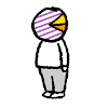
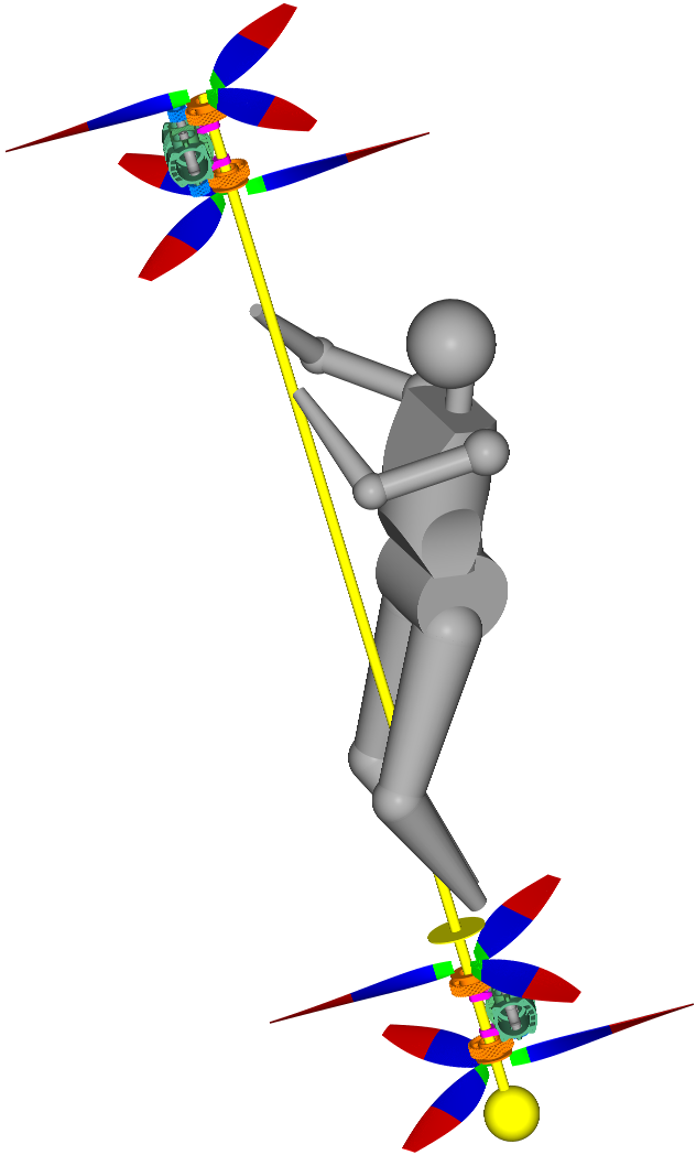
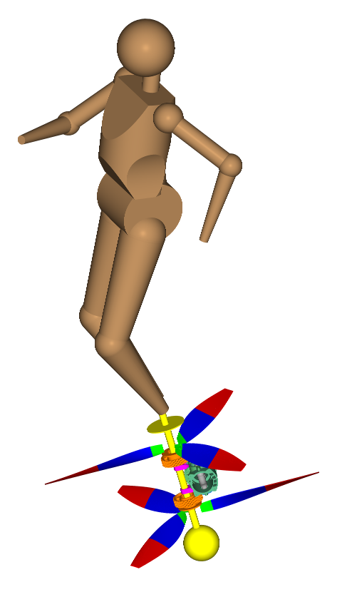
Portable Flyer with and without handlebars:

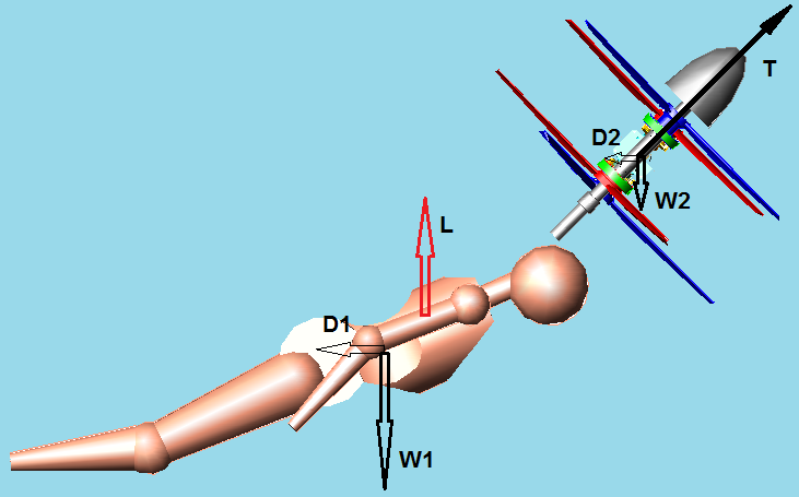
The hands of the pilot hold the handlebars; the hands are supported on pilots arms, which are supported on pilot’s “shoulders /upper-torso”. That is, every force and torque (pair of forces) provided by pilot’s hands come / originate from the “shoulders / upper-torso” (which, in turn, are supported on the rest body).

Either the Portable Flyer is vectored by the shoulders / upper-torso “assembly”, or by the hands (which are supported on the shoulders / upper-torso) holding the handlebars, is the same. The second may seem a little more easy / precise; however the first is also completely functional.


Differently:

Isn’t the “upper-torso / shoulders” assembly pivotally mounted, though a gimbal joint (the spinal cord) to the rest body?

Can’t every other part of the human body (I mean as mass / weight and as aerodynamic control surface) be widely displaced relative to the “upper-torso / shoulders”?

Equivalently, can’t the pilot displace the “upper torso / shoulders” relative to the rest body (limbs / head)?

If the objection has to do with the “height” of the “gimbal joint”, I would say that even if the gimbal joint were much lower (even under the feet of the pilot, say as in the Broom Flyer wherein the “gimbal joint” is just under the feet of the pilot) the Portable Flyer would still be controllable:

Image

And if desirable, instead of holding the pile by the hands, the feet of the pilot can be secured at he bottom of the pile (as in Zapata’s JetPack)to make the re-vectoring of the thrust.

So, there is already a strong wide-angle gimbal joint (it is the spinal cord) and a strong part of the human body (the “shoulders / upper-torso” ”assembly”) where the Portable Flyer can be tightly secured.

The ordinary person can displace all the rest parts of their body relative to the “upper-torso / shoulders / Portable Flyer” assembly to control the flight (from vertical take-off, to hovering, to horizontal cruising, to high speed horizontal cruising, to braking, to hovering again and to vertical landing).


From yet another viewpoint:

Stand on the floor and bend to the left, then to the right, then forwards, then backwards. For how many degrees the average person can bend at all directions?
And why this is less than what is necessary to control the flight by “re-vectoring” the thrust?
If you combine the bending of the spinal cord with the numerous modes of bending of the legs / arms / head, then you have an “infinity” of poses that can be used to control the flight.

Or lie with the chest / torso on a chair, wearing a Portable Flyer (or an equal weight at equal eccentricity), and check how widely you can displace all your rest body parts.

At the end, what more a dragon fly (a libellula) does?
Its “propellers” are its four wings supported on its “torso”.
Its rest body cooperates and the libellula files better than anything else.


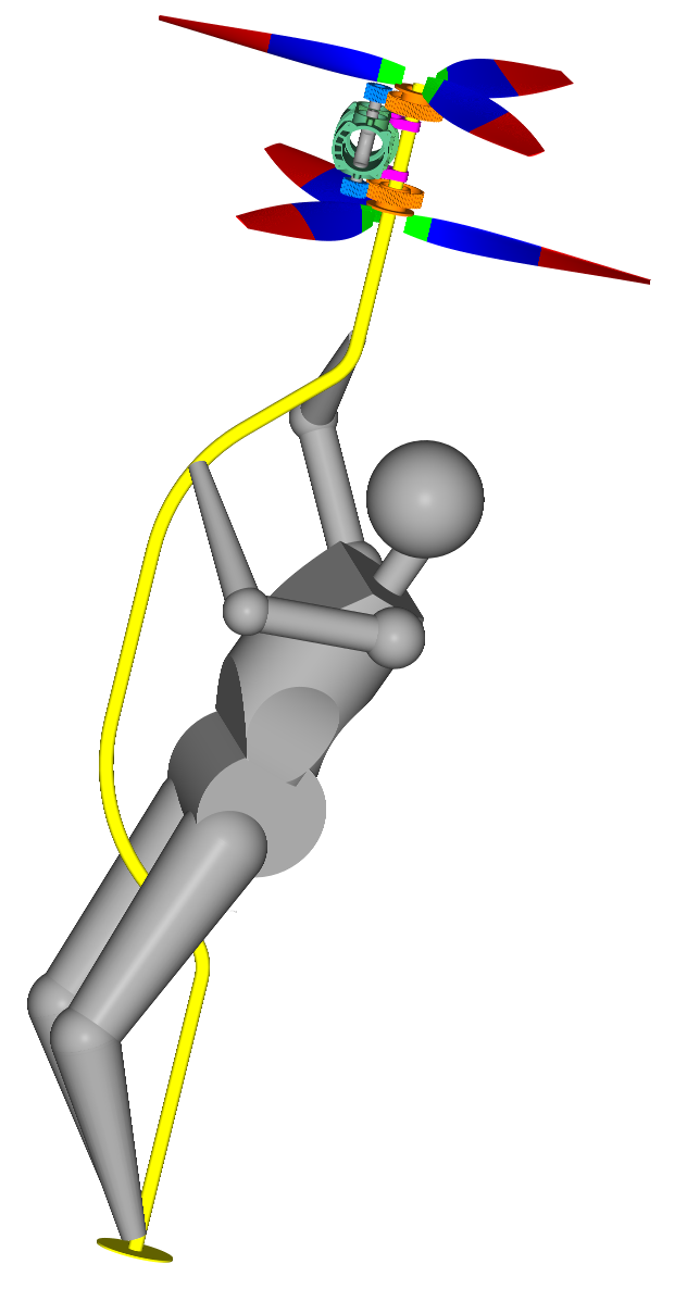
The Portable flyer is more than a GEN-H4.

The GEN-H4 is like the Broom Flyer.

The Portable Flyer can be regarded as two symmetrical (counter-rotating) small GEN-H4 connected together.

The GEN-H4 needs an electronically control brake for the control of the yaw.

The Portable Flyer has built-in aerodynamic control over the yaw (because the pilot is in the high speed downstream of the propellers).

The GEN-H4 is heavy and underpowered. It uses two big rotors. The disk loading is small. The rotors of the GEN-H4 are not for high speed flights. It is a small helicopter.

In comparison the Portable Flyer is like the OPSREY V22: capable for vertical take-off, hovering and landing, but also capable for high-speed cruising and aerobatics on the air.


As the following quote from the top of the page 208 says:

it is not a static equilibrium. It is a step (by step) dynamic correction of an instability.
  • The runner actually rebounds (from foot to foot).

    The equilibrium is dynamic:
    the brain takes feedback from the body (eyes, otoliths, skin, etc) and locates instinctively the foot that is going to abut, and commands properly the muscles in order the body of the runner to take the “right” push from the ground.

    it is not a static equilibrium. It is a step (by step) dynamic correction of an instability.

    In comparison, the brain of the Portable Flyer pilot seems as having an EASIER job to perform.

    For stability what is required is not a center of gravity above the support base, or under the aerodynamic lift, but a way to “feel and react to correct”.

Thanks
Manolis Pattakos
Last edited by manolis on 28 Jun 2020, 07:06, edited 1 time in total.

Rodak
35
Joined: 04 Oct 2017, 03:02

Re: 2 stroke thread (with occasional F1 relevance!)

Post

In comparison the Portable Flyer is like the OPSREY V22: capable for vertical take-off, hovering and landing, but also capable for high-speed cruising and aerobatics on the air.
Oh come on. Aerobatics? More like a death spiral. At least address my comments above re transition to horizontal flight. How is a moment generated to change pitch to achieve horizontal flight? What moment forces do you calculate you can generate by an impingement of the propeller air stream on feet and legs to effect pitch, yaw, and roll whilst in hover? Your control surface is a tiny flexible elevator with limited travel and your aircraft has no stability. This is getting really silly, you want to take flying from the calculable to the mystical.

User avatar
nzjrs
60
Joined: 07 Jan 2015, 11:21
Location: Redacted

Re: 2 stroke thread (with occasional F1 relevance!)

Post

manolis wrote:
28 Jun 2020, 06:35
Hello Gruntguru.

You write:
“The portable flyer concept is perfectly controllable if provided with handlebars and a 2 DOF pivot (flexure perhaps?) at or above the pilot's shoulders. The end result is equivalent to the GEN H-4.”


You cannot claim things like these, without providing “ “explanation, with force diagrams, as to how one transitions from . . ."
Here is a brief report of the rigid body modelling of the gen-h4, including the rotor dynamics, and the dynamics of control of the device in hover.

http://www-personal.umich.edu/~punsingh ... genh4.html

Admittedly the report was made only during a short internship (and re-invents some modelling wheels somewhat) but it might provide an applied introduction to this field for you.

Manolis: there is nothing embarrassing about being unable to do this sort of modelling, but your unwillingness to take quantitative steps to ensure the stability and controllability of the PFs is. I admit freely that I am completely unable to design and manufacture a new engine type. On the other hand, I would never believe that I could or should substitute the specialist skills those people that can build engines have with pictures of babies and animals from the internet.

Rodak
35
Joined: 04 Oct 2017, 03:02

Re: 2 stroke thread (with occasional F1 relevance!)

Post

From the report:
The aerodynamic environment of the two rotors is not the same, since the
lower rotor is significantly affected by the down wash of the upper rotor. Therefore, the two
rotors operate at different rotation speeds to correct the yaw moment.
Manolis, do you compensate for this?

Thanks for the paper nz, very interesting. The conclusion:
The vehicle is unstable in hover, but controllable.

tok-tokkie
36
Joined: 08 Jun 2009, 16:21
Location: Cape Town

Re: 2 stroke thread (with occasional F1 relevance!)

Post

That paper has the word yaw only twice. Right at the top. In the video it was doing complete 360° yaw rotation while stationary wrt the ground. From those two references it is the interaction of the upper rotor downwash on the lower rotor. So, by adjusting the rotor speeds he is able to do those yaw rotations. I was really puzzled how that was done.

Rodak
35
Joined: 04 Oct 2017, 03:02

Re: 2 stroke thread (with occasional F1 relevance!)

Post

tok-tokkie wrote:
28 Jun 2020, 18:15
That paper has the word yaw only twice. Right at the top. In the video it was doing complete 360° yaw rotation while stationary wrt the ground. From those two references it is the interaction of the upper rotor downwash on the lower rotor. So, by adjusting the rotor speeds he is able to do those yaw rotations. I was really puzzled how that was done.
Good point. Quite an elegant solution.

tok-tokkie
36
Joined: 08 Jun 2009, 16:21
Location: Cape Town

Re: 2 stroke thread (with occasional F1 relevance!)

Post

EDIT to my earlier post. Thinking about it it is dead simple. If there was but one rotor then there has to be a tail rotor to balance the reaction torque of the main rotor. So simply by reducing the speed of the one rotor the reaction torque of the faster rotor makes the thing turn around the vertical axis in the opposite direction.

gruntguru
563
Joined: 21 Feb 2009, 07:43

Re: 2 stroke thread (with occasional F1 relevance!)

Post

Same way that yaw is controlled by a vast number of multi-rotor drones eg quad-copter.
je suis charlie

gruntguru
563
Joined: 21 Feb 2009, 07:43

Re: 2 stroke thread (with occasional F1 relevance!)

Post

manolis wrote:
28 Jun 2020, 06:35
You write:
“The portable flyer concept is perfectly controllable if provided with handlebars and a 2 DOF pivot (flexure perhaps?) at or above the pilot's shoulders. The end result is equivalent to the GEN H-4.”
The handlebars are optional.
Think of a bicycle versus a unicycle: the one has handlebars, the other has not; the first is easier to drive, however the second is also controllable and drivable.
My post did not state that the flyer is uncontrollable without handlebars - only that it is controllable with them.

If you had never ridden either - would you rather learn on a unicycle or a bicycle?
je suis charlie

gruntguru
563
Joined: 21 Feb 2009, 07:43

Re: 2 stroke thread (with occasional F1 relevance!)

Post

manolis wrote:
28 Jun 2020, 06:35
If the objection has to do with the “height” of the “gimbal joint”, I would say that even if the gimbal joint were much lower (even under the feet of the pilot, say as in the Broom Flyer wherein the “gimbal joint” is just under the feet of the pilot) the Portable Flyer would still be controllable:

https://www.pattakon.com/Fly_files/Broom_Flyer.png

And if desirable, instead of holding the pile by the hands, the feet of the pilot can be secured at he bottom of the pile (as in Zapata’s JetPack)to make the re-vectoring of the thrust.
This example does not support your case. The broomstick flyer is an example where the pilot has "hand grips" to control the angle of the gimbal joint at the feet.

If you tried to operate the broomstick flyer only with feet strapped to the base it would be unstable and uncontrollable. It is NOT equivalent to Zapata's foot-mounted thrusters because the CG of the thruster is a long way from the pivot. Consider a hover mode situation where the broomstick is leaning say 20* from the vertical and the pilot is vertical. How does the pilot recover from this? Draw a FBD. The mass of the thruster creates a moment at the pivot tending to increase the angle. The pilot resists that moment with his ankles which tends to restore the thruster towards the vertical but also rotates the pilot towards the thruster and away from the vertical. Both pilot and thruster will develop a rotation away from the vertical and there is no way to generate a moment to oppose this.

Similarly with the flyer "fixed" to the shoulders and no handlebars. The CG of the thruster is some distance from the pivot (chest) and whenever the thruster CG is not directly above the pivot, gravity will generate a moment which must be resisted by the pilot (except at high speed where some lift or drag can help to support it).
je suis charlie

Rodak
35
Joined: 04 Oct 2017, 03:02

Re: 2 stroke thread (with occasional F1 relevance!)

Post

If you had never ridden either - would you rather learn on a unicycle or a bicycle?
Bicycle. I've ridden both and they have nothing to do with each other as far as control. You have to learn to ride a bike and you have to learn to ride a unicycle. Now imagine a baby learning to ride a unicycle........

manolis
107
Joined: 18 Mar 2014, 10:00

Re: 2 stroke thread (with occasional F1 relevance!)

Post

Hello Gruntguru.

You write:
  • “My post did not state that the flyer is uncontrollable without handlebars - only that it is controllable with them.”


It is a good opportunity to agree that the difference between:
“this is more difficult, but doable”
and
“this cannot be done”
is huge.


You also write:
  • “ This example does not support your case. The broomstick flyer is an example where the pilot has "hand grips" to control the angle of the gimbal joint at the feet.
    If you tried to operate the broomstick flyer only with feet strapped to the base it would be unstable and uncontrollable. It is NOT equivalent to Zapata's foot-mounted thrusters because the CG of the thruster is a long way from the pivot.

Starting with the two-engines Broom Flyer:

Image

and removing the pole (or stick) and the upper engine, what is left is this version of the Broom Flyer:

Image

which seems quite “equivalent” to Zapata’s foot-mounted thrusters.


You also write:
  • “Consider a hover mode situation where the broomstick is leaning say 20* from the vertical and the pilot is vertical. How does the pilot recover from this? Draw a FBD. The mass of the thruster creates a moment at the pivot tending to increase the angle. The pilot resists that moment with his ankles which tends to restore the thruster towards the vertical but also rotates the pilot towards the thruster and away from the vertical. Both pilot and thruster will develop a rotation away from the vertical and there is no way to generate a moment to oppose this.

“Draw a FBD” :
If it were a static equilibrium, a FBD would be useful.
But here we have a dynamic instability; a FBD is insufficient / inadequate to describe what happens.
For instance, is a FBD or a “Force Diagram” capable / sufficient to describe the running of the runner of the video at the top of the 208 page as he continuously corrects his instability?


The thrust is along the stick (pole, pipe).

The weight of the thruster is analyzed into two forces, one along the stick and another normal to the stick; the first is taken by the thrust, the other is free and equals to the weight of the thruster Wt times sin(20 degrees), i.e.it equals to Wt*0.34.

The weight of the pilot is similarly analyzed into two forces, one along the stick and another normal to the stick; the first component is taken by the thrust, the second is free and equals to the weight of the pilot Wp times sin(20 degrees), i.e. it equals to Wp*0.34.

So the thruster and the pilot together are at an “oblique” free-fall (the track of the fall is 20 degrees from the horizon and the “gravity” acceleration is only 0.34 of the typical gravity acceleration).

When a pendulum (the pilot with the thruster pivotally mounted at pilot’s feet is a pendulum) is at free fall, the support of the pendulum (in our case the pilot) does not apply force or moment to the “weight” of the pendulum (in our case the thruster); the string between the weight and the support of the “pendulum in space” is completely loose:

Image

I.e. the ”eccentric” – from the “pivot” at the feet of the pilot – weight of the thruster does not create a moment the pilot has to react to.

So, what happens?
How the pilot manages to take the control?

The feet / legs of the pilot do apply a pair of forces (a moment) to the stick but not in order to react to the moment of the eccentric (relative to the pivot) weight of the thruster (as explained: the thruster and the pilot are at an oblique “free fall”); the feet / legs of the pilot just turn the thruster about the pivot upwards; the reaction makes the pilot turn at the opposite direction (but at a different angle due to the different mass and mass distribution of the two parts of the assembly).

Now the pilot has two options:

Either he oscillates about the stick, with the stick oscillating about the vertical direction: the Flyer is hovering but it also moves “ forwards” and “backwards” about a middle point (as written again, it is a controllable instability),

Or

The pilot uses his limbs / head (which are into the downstream of the propellers) in order to cancel out the above oscillation and remain (he and the stick) substantially vertical (he still needs corrections from time to time to maintain his pose, but these correction are in another class of magnitude).


You also write:
  • “Similarly with the flyer "fixed" to the shoulders and no handlebars. The CG of the thruster is some distance from the pivot (chest) and whenever the thruster CG is not directly above the pivot, gravity will generate a moment which must be resisted by the pilot (except at high speed where some lift or drag can help to support it).

I think the previous analysis covers this case, too, especially at hovering.

At cruising, the “Portable Flyer thruster” is at an eccentricity from the “pivot” (the spinal cord at the torso of the pilot).

As before, the gravity acts on both, the pilot and the thruster (or Portable Flyer).

As before, both the pilot and the Portable Flyer are at an oblique “free fall”.

The moment (pair of forces) the pilot applies with his torso / shoulders (or with the handlebars) is not in order to take the moment of the eccentric weight of the thruster (i.e. of the Portable Flyer), but in order to turn the mass of the thruster relative to the mass of the pilot (i.e. to re-arrange the two bodies).

If it is not yet clear, please let me know to further explain.


As in the bicycle, as in the unicycle, as when we walk, as when we run, as in the “Pendulum Rocket Fallacy” etc there is not a “static equilibrium”; it is a continuous correction of the instability.

Thanks
Manolis Pattakos

gruntguru
563
Joined: 21 Feb 2009, 07:43

Re: 2 stroke thread (with occasional F1 relevance!)

Post

A FBD is always useful to snapshot a moment in time. The system does not need to be in static equilibrium. If the system is accelerating an imaginary force vector is applied at the centre of gravity - magnitude = ma, direction = opposite to the acceleration. In the diagrams below, the flyer is hovering and thrust is sufficient to maintain altitude. Because the thrust is not vertical, the system is accelerating to the left. The CG shown is combined CG of pilot + flyer. Vector components are shown in some cases but it only necessary to look at the two "resultant" vectors to visualise the overturning couple.

My previous post incorrectly characterised the broomstick system as unstable. Looking at the FBD, the system is experiencing a moment which is tending to rotate the thrust towards vertical. There is also a torque at the hinge (ankles) which is tending to increase the angle between the pilot and the flyer. Provided the pilot can apply sufficient torque to maintain or reduce this angle, the system is as stable as Zapata's. It is not as controllable because controlling the angle requires swinging the mass of the flyer on the end of a long lever. This will respond quite slowly, however it is unlikely this machine would be operated without the pilot hold on to the "stick".

The shoulder-mounted flyer (without handlebars) is less stable. The system is experiencing a moment which is tending to rotate the thrust further away from vertical. Also the mass of the flyer creates a moment which tends to increase the difference between the thrust axis and the pilot axis (the axis passing through the hinge and the pilot's CG). To recover from this position to a stable hover requires the pilot to reverse the angle of the hinge to move the CG to the right of the thrust axis. To operate this system without handlebars requires a rigid connection at the shoulders with zero backlash. If this action requires "arching" his back, it will be impossible to recover from extreme angles.

Image
je suis charlie

manolis
107
Joined: 18 Mar 2014, 10:00

Re: 2 stroke thread (with occasional F1 relevance!)

Post

Hello Gruntguru.

You write:
  • A FBD is always useful to snapshot a moment in time. The system does not need to be in static equilibrium.

The question is how many “moments in time” are required to correctly describe the “running of the runner” or the “walking of a person” or . . .
Thousands?
I would say Millions.
Those who persistently ask for “force diagrams” do really understand what they ask?

Thanks
Manolis Pattakos

manolis
107
Joined: 18 Mar 2014, 10:00

Re: 2 stroke thread (with occasional F1 relevance!)

Post

Hello Gruntguru.

You write:
  • In the diagrams below, the flyer is hovering and thrust is sufficient to maintain altitude. Because the thrust is not vertical, the system is accelerating to the left. The CG shown is combined CG of pilot + flyer. Vector components are shown in some cases but it only necessary to look at the two "resultant" vectors to visualise the overturning couple.

So, you take “one moment in time” (one instant) for which you show the thrust force T which is offset to the overall center of gravity.

Then you replace the thrust force by an equal / parallel force passing from the overall center of gravity (the direction of this force in the FBD should be opposite, I think) and a moment (the “circular” arrow at top) equal to the thrust force T times its eccentricity from the overall center of gravity (how many forum members do really understand and can apply this “equivalency”?).

Then we should add the overall weight (a vertical – downwards looking – force from the overall center of gravity).

Then we should take the sum of all forces (which is a force acting on the overall center of gravity, is normal to the T, and is looking to the left / left-bottom) and the free moment and calculate their effect.
The result would be an acceleration of both parts (the thruster and the pilot) towards the left / left-bottom ( I called this acceleration an “oblique free fall”), and an accelerating clock-wise rotation of the assembly about its center of gravity.

Now comes the “living” pilot to control the situation:

The pilot displaces – either by his hands or by his feet (or lower legs) – the pole / stick until the thrust T to point to the right creating a reverse moment and a (more or less) “opposite” overall force (it will point to the right / right-bottom).
Now the Flyer/Pilot assembly accelerates at the ”reverse direction” (to the right / right-bottom) and turns “counter-clock-wise”.
  • For those who still doubt

    The angular displacement of the thruster about the pivot at the feet of the pilot causes an “opposite” displacement of the pilot.

    Just think what happens during a skydive:

    Can the skydiver open widely and then close completely his legs?
    Can the skydiver retract his limbs / head to form a “ball” and then extent his body parts to straight his body and continue his fall like an arrow head-down?

    The same happens when the pilot holds the Broom-Flyer thruster: the thruster is (becomes) a part of pilots body; the pilot can displace it at all directions, provided his legs, head and arms are displaced properly to “balance” the displacement (linear and angular) of the thruster.
According the previous, instead of true hovering we have a combined linear and angular oscillation.

If the thruster was a rocket, and the assembly was in the space (no air), the oscillation would continue.
But being in the air, the oscillation will progressively fade-out due to the aerodynamic friction of the parts with the surrounding air.

And if the pilot uses his head / limbs (being in the downstream of the propellers), he can almost instantly cancel out the above linear and angular oscillations and turn to “stable” hover (correcting continuously the instability by smooth , almost unnoticeable, movements of his body parts (which hold and displace the pole)).


You also write:
  • The shoulder-mounted flyer (without handlebars) is less stable. The system is experiencing a moment which is tending to rotate the thrust further away from vertical. Also the mass of the flyer creates a moment which tends to increase the difference between the thrust axis and the pilot axis (the axis passing through the hinge and the pilot's CG). To recover from this position to a stable hover requires the pilot to reverse the angle of the hinge to move the CG to the right of the thrust axis. To operate this system without handlebars requires a rigid connection at the shoulders with zero backlash. If this action requires "arching" his back, it will be impossible to recover from extreme angles.


I can’t follow.

So, when the pole is pivotally mounted to (near) the feet of the pilot, the system can recover to hovering, but when the pivot is closer to the overall center of gravity the recovery is problematic?

The thrust of the Portable Flyer (say, the plane defined by the axes of the propellers) cannot lean this way:

Image

What is shown at right is a thrust at an eccentricity of about 0.5m from the overall center of gravity, and a pivot at the top of pilot’s head. No matter how hard the pilot tries, it is impossible to achieve such eccentricity of the thrust.

The actual arrangement of the Portable Flyer:

Image

keeps this eccentricity much smaller (the pivot / gimbal joint is the spinal cord of the pilot in his upper torso).

Drawing the thrust at the allowable eccentricity, the pilot in order to recover just bends a little his waist and more his legs to the right displacing the overall center of gravity to the right of the thruster axis.
This creates an opposite moment that turns the Portable Flyer clockwise. Etc, etc. . .

It is similar to the way Mayman controls his JetPack.


As for the:
  • Also the mass of the flyer creates a moment which tends to increase the difference between the thrust axis and the pilot axis (the axis passing through the hinge and the pilot's CG).
as explained, when both parts of the Pendulum (the thruster (i.e. the Portable Flyer) and the pilot) are at a “free fall” (oblique or straight), the weight of each of them cannot apply forces or moments to the other: they both free fall).


PS.
If you agree with the above, please explain them to the rest forum members: you are a third party and you are English speaking.

Thanks
Manolis Pattakos

Post Reply