You write:
silly old Laverda !
making and selling about 2000 3C machines with solid-mounted flat crank 1000cc and 1200cc engines
using terminology like 'feelings' and 'sense of a turbine' - that's what's not reasonable
OK.
So let’s maths and physics “talk”:
The above plots were created with the pattakon balance program.
At left of each plot it writes what it is.
The plots cover 360 crank degrees horizontally.
Spot on the units per horizontal line (say, 20Kp/horizontal line).
The plots are for the conventional I3 (crankpins 120 crank degrees from each other), unless it is written at the head of the plot that it is for the I3_Flat_Crank engine (Laverda etc).
The first plot (that like "noise") shows the free inertia force of the conventional I3. Nearly zero.
The second plot (or slide) shows the free inertia torque of the conventional I3 and its Fourier Analysis : the free inertia torque is 35Kpm (= 350mN) and is of third order (count the peaks of the curve into 360 degrees).
The third plot shows the free inertia moment of the conventional I3 (case without balance webs on the crankshaft). The peak of the inertia moment is over 250Kp*m (2,500mN).
The fourth plot shows the free inertia moment in case balance webs are secured to the crankshaft. Now the peak is about half (160Kp*m (1,600mN)) but the inertia moment is not, any longer, on the plane defined by the cylinder axes; it is a rotating inertia moment.
The fifth plot is the free inertia moment of the conventional I3 in case an external balance shaft (rotating with crankshaft speed, at opposite direction) is added. Now the peak of the free inertia moment is only 60Kp*m, is on the plane of the cylinder axes and is of second order.
The sixth plot is the free inertia force of the I3-Flat_Crank (Laverda like), with balance webs on the crankshaft. Its peak is 1,800Kp (18,000N). Compare it to the zero free inertia force of the conventional I3.
The seventh plot is the Fourier analysis (and re-synthesis) of the sixth curve. Here you can see how strong is the first order free inertia force, the second order free inertia force and so on. The first order is not as strong as the second order, however the first order has half frequency and may be more annoying.
The eight curve is the free inertia torque of the I3-Flat_Crank. It is mainly of second order and its peak is 95Kp*m, about three times higher than the free inertia torque of the conventional I3.
In this curve you have to add the combustion torque curve, which is quite asymmetrical curve with a big pulse between 0 and 180 degrees, and a small (half in size) pulse from180 to 360 degrees.
The last curve is the free inertia moment of the I3_Flat_Crank. Net zero due to the symmetry of the engine (the two side pistons at zero phase difference).
Having said all these, these two engine have several reasons to be quite different as regards their vibrations. Don’t they?
For the combustions, the one has a strong pulse per 360 degrees and a weak pulse in the middle of the 360 degrees intervals. It would remind a single cylinder. If you add the strong 2nd order free inertia torque. . .
The other has equal, equally distributed power pulses (one per 120 crank degrees), which – combined with the weak symmetrical 3rd order inertia torque has all it needs to remind turbine.
Now it is your turn to explain what makes the vibrations of the two arrangements (Laverda’s and conventional) similar.
PS1.
The engines (conventional I3 and I3_flat_crank) have same pistons, same connecting rods, same cylinder axes distance)
PS2.
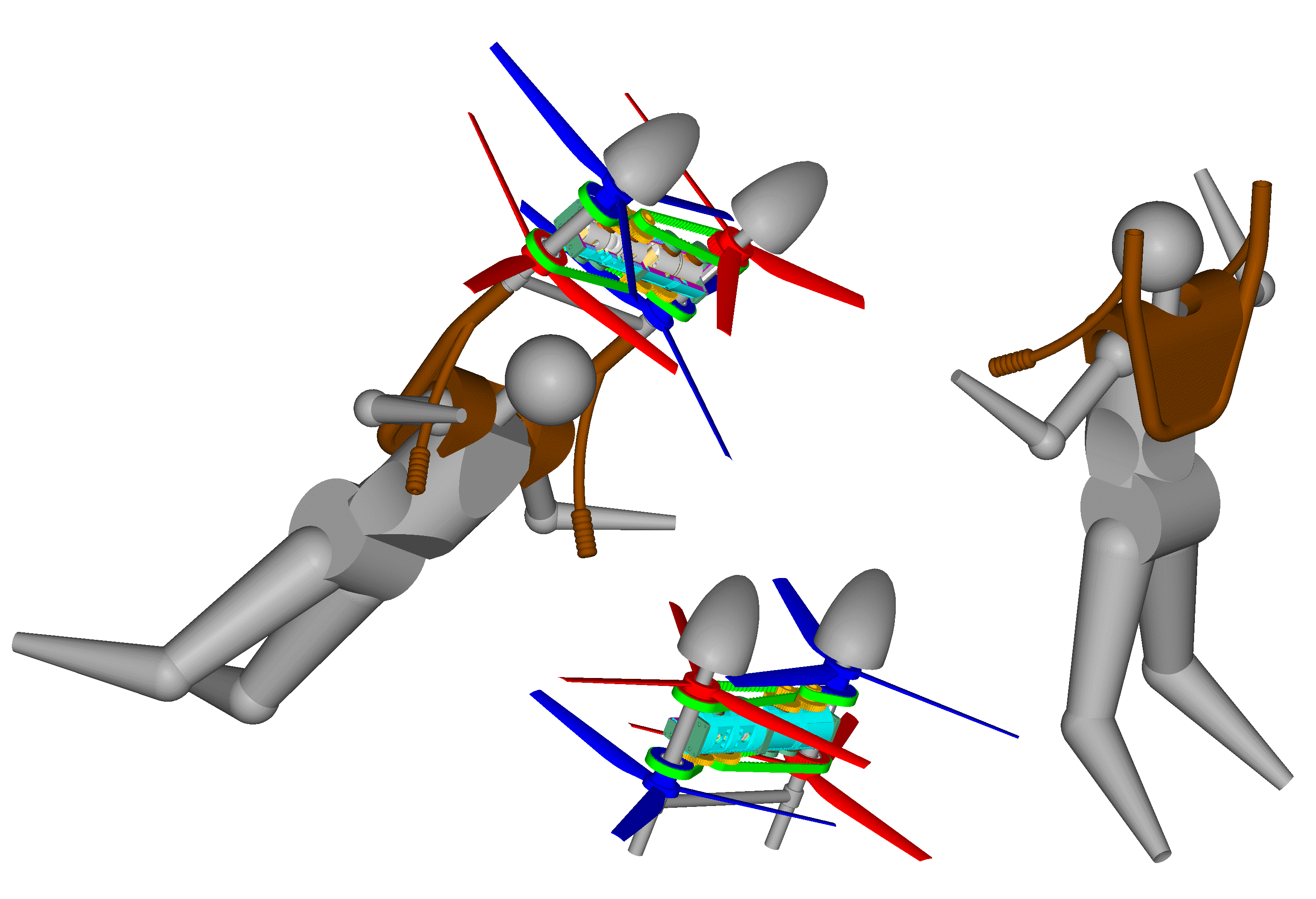
It is a pity that the “engineers” / “scientists” of the forum can’t get how a personal flying device can recover from nose-down flight to nose up flight with only control the body of the pilot.
Maybe the specific problem of control is too simple for them to deal with.
Thanks
Manolis Pattakos

 .
.