You write: “manolis, what of the 'big bang' 500 four cylinder GP twostroke engines where all combustions take place over 60 degrees of crank rotation.
Or the parallel twin twostrokes where the cranks are at 90 degrees, like a v twin would be.
These engines won GP races, there is a very good reason for this.”
The “Big Bang” characteristics don’t fit with engines for normal use (say for cars, boats, gyros, airplanes).
In the analysis / comparison of the two three-cylinder in-line 2-stroke arrangements (page 233, top), the conventional even-firing appears far better than the “two up, one down”.
Do I miss something?
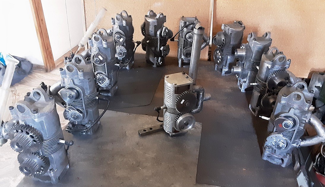
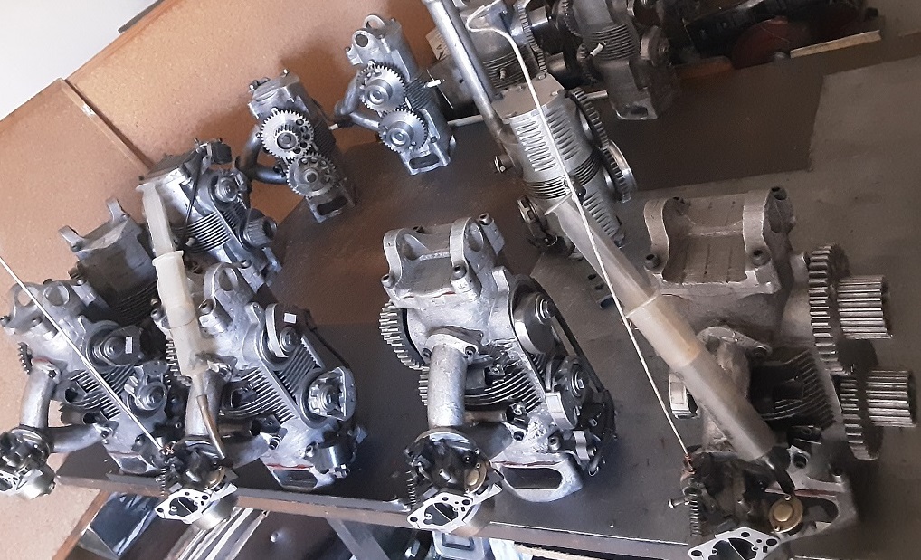
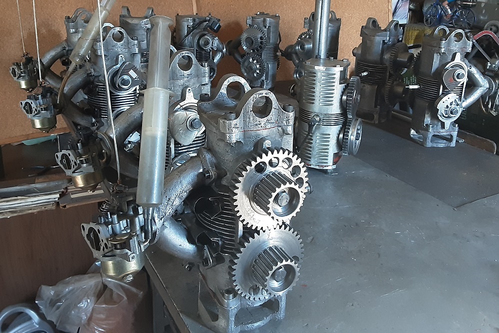
In the following photos they are shown the first OPRE Tilting prototype engine (at the center; its casing, pistons, connecting rods and covers are made of billet aluminum “7000”) surrounded by ten “all-cast” OPRE Tilting Engines (made of A356-1 aluminum alloy (6.5-7.5% Si, 0.3-0.45% Mg); the material is from used light-alloy car-wheels):
Two of the engines (4th and 5th from right, those with the short top covers), are “broom version" power plants (power output from opposite side of the two crankshafts).
The ten "all cast" engines are for four Portable Flyers and two "Broom" Flyers.
What is missing is:
the ignitions from the three engines at right (first photo),
the machining (CNC mill) of the sprockets on the hubs of the 8 synchronizing gearwheels (the rest 12 are ready),
PORTABLE FLYER ARCHITECTURE AND BASIC DESIGN CHARACTERISTICS
The PORTABLE FLYER comprises two OPRE Tilting Engines secured to each other to form (with their casings) the personal flying device’s “backbone”.
The one engine drives two counter-rotating propellers arranged above the backbone, the other engine drives two counter-rotating propellers arranged below the backbone. The following presentation deliberately focuses on the engines because the PORTABLE FLYER is actually its engines . . .
The common instant pressure onto the crowns of the two opposed pistons of
an engine, and the fully symmetrical load on the two crankshafts is eliminating
the loading of (and the frictional losses in) the synchronizing gearwheels and
is allowing their cooperation without lubrication if desired.
End of Quote.
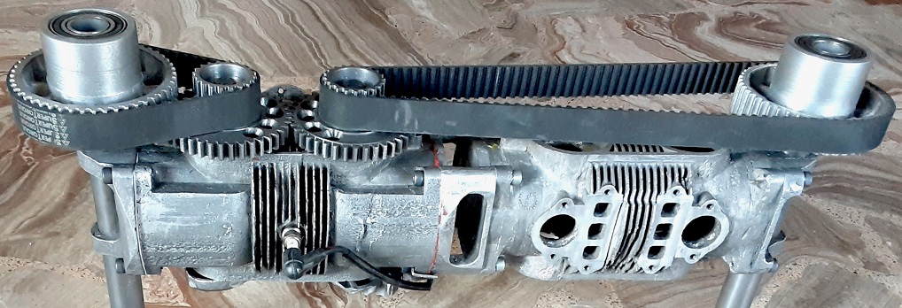
In this photo:
only the left OPRE Tilting engine is functional (the right one is "empty"; it is utilised to complete the "backbone" of the Portable Flyer).
The power from the two crankshafts of the left engine is transmitted, through the small sprockets (machined on the hubs of the synchronizing gearwheels) and the short (left) and long (right) toothed belts, to the big sprockets at the left and right ends of the Portable Flyer.
On the hubs of these big sprockets the propellers (not shown) are secured.
The transmission ratio from each crankshaft to its propeller is 2.4:1.
With the two crankshafts of the OPRE Tilting engine operating at zero phase difference and with symmetrical load (the two intermeshed counter-rotating propellers), the synchronizing gearwheels need neither covers, nor lubrication because excluding the cranking, for the rest time they operate unloaded.
Hello Mudflap
You write: "Even for low specific sliding designs, uncoated metallic gears will eventually fail."
Eventually everything will fail.
However the synchronizing gearwheels of the OPRE Tilting engine are the last parts of the engine that will fail just because they run unloaded.
manolis, That was the only explanation I thought you could come up with.
In the real world I think you will have trouble with those dry gears. No matter what, you are going to get opposing loads on your propellors, wind gusts, differing prop wash, those gears will see load. Rather optimistic of you I believe.
Why would you not put them at least in a housed oil bath?
Last edited by uniflow on 18 Oct 2020, 01:23, edited 1 time in total.
You write: "Even for low specific sliding designs, uncoated metallic gears will eventually fail."
Eventually everything will fail.
However the synchronizing gearwheels of the OPRE Tilting engine are the last parts of the engine that will fail just because they run unloaded.
Thanks
Manolis Pattakos
I'm a afraid you are terribly wrong.
Yes the mean torque transmitted through the gears will be very close to 0, however there will be dynamic gear impacts which will result in considerable loads.
If the angular velocities of the 2 cranks were always exactly the same the gear pair would not be needed at all once the engine is running. In reality there will always be a minute speed difference which will cause the gear teeth to move through the backlash and impact. In this case the instantaneous gear torque is purely a function of the effective inertia behind each gear and the square of relative angular velocity (think of it as the classical elastic collision in elementary mechanics).
Go ahead and run the engine at full output for say an hour or so and then evaluate the condition of the tooth flanks to convince yourself.
I count 11 engines in that photo. Have you run a single test engine to destruction? How long did it run? What was the test cycle? What was the output? What sort of problems did you have? What did the gears look like after 20 hours? Why build so many if you haven't actually tested the design? No one gets it exactly right the first time; seems weird to me.....
manolis, good on you, you are actually building hardwear, I like that.
But just because you might think you win a word debate, doesn't make the the answer necessarily correct. Put a gear case around those gears please, if nothing else it will stop someone loosing a finger, or worse.
You write: “This is probably a dumb question, but if they are unloaded why do you need them?”
The problem is that without the synchronizing gearwheels the “equilibrium” is “unstable”:
If the phase difference between the two crankshafts from exactly zero becomes (for some reason) 0.1 degrees, then the created loads (due to the non-zero phase difference) increase it to 0.2 degrees, then to 0.5 degrees, then to 2.0 degrees and so on (the larger the offset, the faster the increase of the offset), and finally the two crankshafts will get completely out of phase causing an engine stall.
The synchronizing gearwheels keep / maintain the phase difference adequately small.
Hello Uniflow and MudFlap
Nothing can run completely “unloaded”.
However when the load is adequately small / weak, then the wear becomes too slow to affect the overall reliability or TBO (Time Between Overhauls) of the engine. Other parts wear faster.
By the way:
The synchronizing gearwheels in the photos are not hardened.
If during the tests they show signs of wear, then they will undergo “nitride surface hardening”.
So what is your estimated TBO? 20 hours? 50 hours? 1000 hours? For flight stuff you had better be conservative. A failure in flight means, with this device, death.
Thats OK manolis, take no notice of us, you know best and we can offer you nothing.
Having actually built and am test flying my own twostroke aviation engine, what could I possibly offer?
But I will offer this, at 500 feet you will have a completely different out look, suddenly a reliable engine matters. Even in my autogyro Im not fond of an engine failure but at least I can recover to fight another day, you wont be so lucky I think.
I expect there will be little problem with the 2 synchronizing gears. If they do in fact wear more than expected I would replace one with a phenolic laminate gear. Tufnol was the original trade name. Use the fabric grades, not the paper grades. Paired with a steel gear there is no need for lubricant. If the steel gear is hardened even better.
What really matters is the engines and the control of the flight.
PORTABLE FLYER CONTROL
To analyze the exact motion and the response of the pilot is difficult, if not impossible.
When a problem is difficult, the reductionism is the way to go.
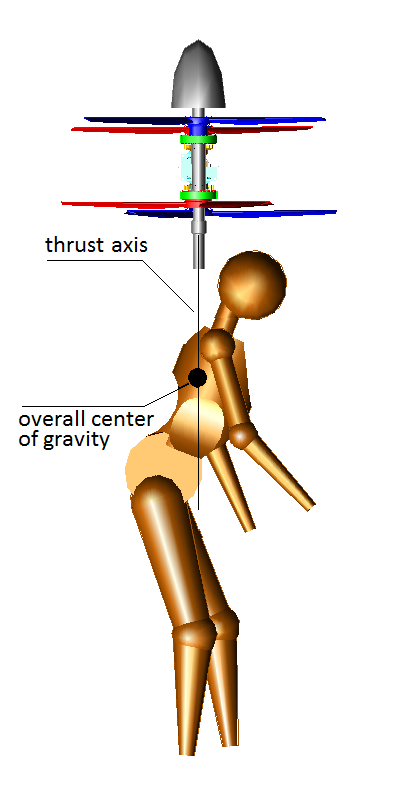
1. The astronaut.
The case with the astronaut who “flies” in empty space (out of the air), outside or inside a gravitational field, shows that the “Weight Displacement Control” provides full control.
The propulsion unit provides a pure thrust force and is secured to astronaut’s body.
The pilot displaces the overall center of gravity relative to the thrust force axis by varying their body posture.
The offset thrust force – relative to the center of gravity – turns the assembly and redirects / re-vectors the thrust force.
The astronaut can turn at any desirable direction and can go from any point A to any point B avoiding any obstacles between these points, following any path they like.
The astronaut can also take off and land.
Note:
The photo shows just an astronaut, not the astronaut we talk about.
Without air to interact, the astronaut has no aerodynamic control, at all.
The thrust axis is what matters, not the exact point where the propulsion unit is located; for instance, if the “thrust provider” has zero weight, then either the thrust provider is above the head of the astronaut, or below their feet, or around their waist, it is exactly the same.
And talking for center of gravity: the Portable Flyer is to be driven by thin persons, by women, by gymnasts, by fat persons, by anyone; to provide / define the exact weight and the exact location of the center of gravity is meaningless, especially considering that the center of gravity is displaceable (for the “weight displacement control”) and that the overall weight decreases as the fuel is consumed.
2. The wind dancer.
In the case with the “wind dancer” (video) the “Weight Displacement Control” is not applicable.
Why?
Because the thrust force (i.e. the weight of the “wind dancer”) permanently passes through the center of gravity of the “wind dancer” (this is the definition of the center of gravity in physics).
With zero offset of the thrust force (i.e. of her weight) from her center of gravity, there is no torque to turn / to re-vector the “wind dancer”.
But the “wind dancer” is in a high speed air stream (say, 150mph) and her body can interact with the air creating forces and torques that turn and displace her.
She has full control over her flight: she can turn at any direction (pitch, yaw, roll) in a fraction of a second, she can also move at any direction (upwards, downwards, to the left, to the right, forwards, backwards).
3. The Portable Flyer
With its "true neutral propulsion unit" (neither vibrations, nor reaction torque, nor gyroscopic rigidity; only a force that can "instantly" and effortlessly be vectored towards the desirable direction) the pilot has full control over their flight by combining both:
the “Weight Displacement Control” (of the astronaut) and the “Aerodynamic Control” (of the “wind dancer”).