............
1. When the rider of the crossplane will use high revs, or will go fast, or will race, the vibrations will be too strong and the riding will be uncomfortable. ............
A crossplane 4-cylinder without a balance shaft does not fit with modern vehicles.
The addition of a balance shaft makes it perfect as regards its inertia vibrations; the pain is worth the gain
2. As for the relation of the low revs with the vibrations, the Norton Commando with the elastic mounts of its Twin engine (crankpins at 0, 360 degrees) vibrated strongly at the lower revs: ...........
I believe that ....
Helmut Fath made his engine to win GPs with less vibration than any other 4 cylinder inline engine ....
because the crossplane crank gives nil unbalanced primary and secondary inertia forces .....
this regardless of what either engine type could have done with counterbalance shafts .. and ....
regardless of the unbalanced inertia moments (of the crossplane)
he had tried eg the Camathias Gilera - and found vibration from its unbalanced secondary inertia forces
(he had no problem with his crossplane at 14-15000 rpm) ...
and the sources you linked suggest that the some superbike 4s no longer have secondary force counterbalance shafts
vibrations of solid-mounted (motorcycle) engines are always least at low rpm - my 50 years of experience tells me
the Commando (yes I've ridden one) is elastic-mounted so resonates below 40 mph in top gear - so what ?
I think "Inertia Torque" is a terrible misnomer for what is actually a cyclic angular variation of the output. The resulting variation in "torque" is a function of this variation but equally a function of engine speed, inertia of the load and elasticity of the connection to the load (drivetrain). Consequently the abundant dynamic solutions that have been used historically can only "fix" the problem at certain speeds. The problem is angular displacement and can be completely solved with a simple kinematic solution like the PatVAR.
What I call inertia torque is simply the torque produced by the piston acceleration. It is part of the excitation torque on the drivetrain. I think what you call inertia torque is the dynamic torque at different points in the driveline and represents the response to the excitation. As you say this quantity is much more difficult to calculate since the inertia, stiffness and damping of the system need to be considered. However if the driveline was perfectly rigid then the two would be equal.
I think the fact that PatVRA is a kinematic solution is actually part of the problem. That means that the torque amplitude and frequency it produces are monotonic functions of engine speed and the phase angle is fixed.
Going back to TC's point about dealing with the firing excitations which in an even firing inline 4 produce the same 2nd order excitation as what I call the inertia torque but their phase angle is different and changeable with engine speed and load.
So for example if the inline 4 engine is boosted it would produce a high 2nd order firing excitation at a low engine speed. The PatVRA would only produce a weak "cancelling" torque with a phase angle which would be different than the ideal 180 degrees. By contrast a CPA tuned to the 2nd order has free rollers which will respond with the correct phase angle to whatever the perturbation is because they are not kinematically constrained.
Sure the PatVRA will work in an inline 4 where the inertia torque has a similar amplitude to the firing torque amplitude such a high speed N/A engine but does such an application really benefit that much from such a device ?
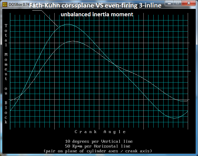
Here is the comparison of the unbalanced inertia moments of the in-line even-firing 3-cylinder with the crossplane uneven-firing Fath-Kuhn 4-cylinder (same pistons, same piston stroke, same distance between neighbor cylinder axes, same revs).
At 0:15 of the following “Introducing the Triumph Moto2 765cc triple engine” video, it is shown the first order balance shaft (great sound):
The engine
Based on the new 2017 Street Triple engine, the Triumph Moto2TM 765cc triple engine was developed and tuned for a major step up in power and torque.
In ‘road’ setup the new 765cc engine delivers the highest-ever level of performance for a Street Triple, delivering 121 horsepower at 11,700 rpm and 57 foot-pounds of torque at 10,800 rpm.
Without the balance shaft, power, cost and weight is saved, yet they use a balance shaft.
Quote from page 222 for a twin even-firing two-stroke:
I built a balance shaft and bolted it up externally to the engine as a test - with counter rotating bob weights flying around in mid-air. The difference was like night and day! I could not believe how smooth this new addition made the engine feel.
As the crossplane 4-cyl, similarly the plane-crank 4-cyl “gives nil unbalanced primary inertia forces .”
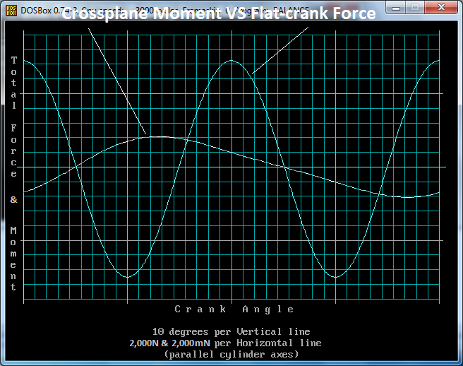
Let’s “compare” the ~15,000N unbalance 2nd order inertia force of the plane-crank 4-cyl with the ~4,000mN (mainly 1st order) unbalance inertia moment of the corssplane 4-cyl Fath-Kuhn (same pistons, same stroke, same cylinder-to-cylinder offset same r.p.m).
Let’s suppose that there are only two mounts, both at the bottom of the engine at a, say, 0.33m distance from each other, the one at the left side of the motorcycle frame, the other at the right side of the motorcycle frame.
Each of the mounts of the flat-crank engine receives a force of 15,000/2=7,500N of 2nd order (parallel forces at the same direction).
Each of the mounts of the cross-plane engine receives a force of 4,000mN/0.33m=12,000N of 1st order (parallel forces at opposite direction).
I.e. as compared to the cross-plane mounts, the mounts of the Flat-crank deal with weaker forces having double frequency.
With the engines revving at the same rpm, the time the second order force of the flat-crank acts on its mount at a direction (say upwards), is half than the time the first order force of the crossplane acts on its mount before changing direction, which means the deformation of the frame at the mounts is substantially larger in the case of the crossplane because the forces are heavier and because they act at a direction for longer (suppose there are no elastic mounts).
Having said these, maybe Fath who
“had tried eg the Camathias Gilera - and found vibration from its unbalanced secondary inertia forces (he had no problem with his crossplane at 14-15000 rpm) ...”
was meaning (by vibrations) not the unbalanced inertia forces of the plane-crank 4-cyl engine but the heavy second order inertia-torque passing through the transmission line to the rear wheel spoiling the feeling of the rear tire hooking with the road.
Hello Mudflap
You write: “So for example if the inline 4 engine is boosted it would produce a high 2nd order firing excitation at a low engine speed. The PatVRA would only produce a weak "cancelling" torque with a phase angle which would be different than the ideal 180 degrees. By contrast a CPA tuned to the 2nd order has free rollers which will respond with the correct phase angle to whatever the perturbation is because they are not kinematically constrained.”
The PatVRA cancels out the second order inertia torque of the flat-crank even-firing four-in-line and passes to the transmission line only the combustion torque.
I.e. it does what the V-8 engines do internally (there are two sets of four pistons, with each set of four pistons having a significant variation of its kinetic energy during a crank rotation, and with the total kinetic energy of the two sets of pistons being constant during a cycle), and what the Wankel Rotary engines do: it allows only combustion torque to pass to the transmission.
The PatVRA does what the cross-plane 4-cylinder R1-Yamaha engine, but better: because the power pulses have equal distance from each other and are all equal in size.
Differently:
If a V-8 or a Wankel Rotary is boosted, the power pulses arriving to the gearbox increase in size.
I can't see the problem.
If an inline-4 crossplane YAMAHA R1 or FATH-KHUN is boosted, the power pulses arriving to the transmission would increase just like the power pulses in the case of the PatVRA with the flat-crank.
Again I can't see the problem.
The PatVRA cancels out the inertia torque and passes to the gearbox, just like the V-8, the Wankel Rotary and the crossplane 4-cyl, pure combustion torque pulses.
PS.
At the middle of page 244, the post with the speed of the air hitting the pilot (a more interesting topic than the vibrations of the reciprocating piston engines) is still unanswered.
May I suppose that there are no objections?
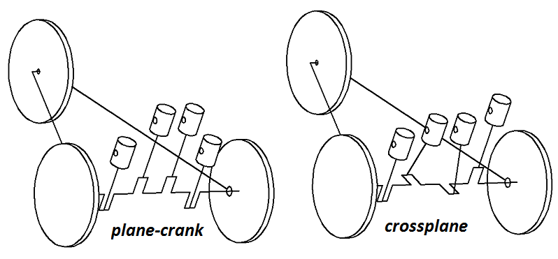
In the following “demonstration” plot two vehicles are standing on a road:
The crankshaft of the 4-cylinder engine of each vehicle (plane-crank at left, cross-plane crank at right) is the drive shaft secured on the two (rear) wheels.
The cylinders of the engines (not shown) are arranged vertically.
The cylinder heads are removed (no combustion in the cylinders).
We apply a horizontal initial push onto the two vehicles and then we leave the vehicles to move free (suppose zero friction).
The velocity of the right vehicle (crossplane crank, zero inertia torque) will be constant.
The velocity of the left vehicle will be variable:
When the four pistons are at their top and bottom dead centers (as in the plot) the velocity of the vehicle will be at its maximum (because the kinetic energy of the set of the four pistons is at its minimum).
90 degrees of wheel-rotation (or of crankshaft rotation) later, the vehicle speed will be at its minimum (because the kinetic energy of the set of the four pistons is at its maximum).
Without applying external forces to the vehicle, its total kinetic energy remains constant; if the kinetic energy of the reciprocating pistons increases, the vehicle speed decreases, and vice-versa.
With the two vehicles moving side-by-side, the left one will be ahead of the other two times per wheel rotation, and behind the other two times per wheel (or crank) rotation.
If the crankshaft of the left vehicle was connected to the wheels by two PatVRA mechanisms, then both vehicles would move at constant speed.
Things are not too different when a typical car with 4-cylinder plane-crank even-firing engine is driven on the road.
There isn’t noticeable increase – decrease of the vehicle speed, however there is a significant oscillation of energy between the vehicle and the engine causing vibrations etc.
.....
The Ve is the “air speed hitting the pilot”, while the V0 is the cruise speed.
For simplicity suppose that at 160mph cruise speed, it is required the same thrust force F as at hovering (wherein the V0 is zero).
So, if at hovering we need a Veh=100mph in order to create the necessary thrust force, and the same thrust force is required at V0c=160mph cruise (the index h is for hovering, the index c is for cruising), then:
Veh^2 = (100mph)^2 = Vec^2-V0c^2 = Vec^2-(160mph)^2, which gives:
Vec=(100^2+160^2)^1/2 mph = 189mph (~300Km/h)
189mph is only 29mph (and not 100mph) higher than the cruise speed.
.......
The thrust required for 160mph (71m/sec) cruise is less than the thrust required at hovering.
.....
whether relative velocity after the prop is 189 mph or a bit less (because cruise thrust is less than the hover thrust) ....
won't relative velocity eg round the pilot's head/body be higher due to the 'blockage' cross-section area of head/body
20% higher ?
90 degrees of wheel-rotation (or of crankshaft rotation) later, the vehicle speed will be at its minimum (because the kinetic energy of the set of the four pistons is at its maximum).
Wait wait wait. Do i understand you correctly that you state that the pistons will reach their maximum velocity at 90°, because highest kinetic energy is the same as highest velocity, right?
If so, this is complete BS. Maximum piston velocity does not happen at 90° crank angle.
What I call inertia torque is simply the torque produced by the piston acceleration. It is part of the excitation torque on the drivetrain. I think what you call inertia torque is the dynamic torque at different points in the driveline and represents the response to the excitation. As you say this quantity is much more difficult to calculate since the inertia, stiffness and damping of the system need to be considered. However if the driveline was perfectly rigid then the two would be equal.
I think the fact that PatVRA is a kinematic solution is actually part of the problem. That means that the torque amplitude and frequency it produces are monotonic functions of engine speed and the phase angle is fixed.
Those are the precise characteristics of inertia torque so the PatVRA can cancel the "inertia torque" exactly (something that dynamic system cannot do because the amplitude of "inertia torque" is a function of downstream inertia eg when a different gear ratio is selected.
A useful way to look at inertia torque is to remove the cylinder head and replace combustion with an electric motor added to the front of the crankshaft. Inertia torque will excite driveline vibrations. Adding a PatVRA will eliminate that excitation regardless of speed, driveline compliance or gear ratio.
I disagree, the inertia torque amplitude is independent of downstream inertia. The inertia torque per cylinder is just a function of reciprocating mass, stroke, rod length and engine speed.
Say you remove the cylinder head and turn the crank at 5000 rpm with an electric motor at the front and measure the angular oscillations of the flywheel end.
Next you increase the inertia of the flywheel and repeat the experiment - you will find that the angular oscillations decrease - they are inversely proportional to the inertia.
That is because the excitation torque has stayed the same and angular acceleration being equal to torque divided by inertia has decreased.
I disagree, the inertia torque amplitude is independent of downstream inertia. The inertia torque per cylinder is just a function of reciprocating mass, stroke, rod length and engine speed.
Say you remove the cylinder head and turn the crank at 5000 rpm with an electric motor at the front and measure the angular oscillations of the flywheel end.
Next you increase the inertia of the flywheel and repeat the experiment - you will find that the angular oscillations decrease - they are inversely proportional to the inertia.
Yup - and the torque oscillations (we are calling this "inertia torque" aren't we) increase - they are directly proportional to the downstream inertia.
. . . and "independent of downstream inertia"????
whether you look at it as torque or angular, we both agree the amplitude depends on downstream inertia.
Last edited by gruntguru on 30 Nov 2020, 22:56, edited 1 time in total.
“90 degrees of wheel-rotation (or of crankshaft rotation) later, the vehicle speed will be at its minimum (because the kinetic energy of the set of the four pistons is at its maximum).”
You write:
“Wait wait wait. Do i understand you correctly that you state that the pistons will reach their maximum velocity at 90°, because highest kinetic energy is the same as highest velocity, right?
If so, this is complete BS. Maximum piston velocity does not happen at 90° crank angle.”
As I write, what counts is not the kinetic energy of each piston, but the kinetic energy OF THE SET of the four pistons.
Considering constant the angular velocity of the crankshaft, the kinetic energy of the set of the four pistons of the plane-crank 4-in-line engine maximizes at 90 and 270 crankshaft degrees and minimizes at 0 and 180 crankshaft degrees (i.e. when the two pistons are at their TDC and the other two pistons are at their BDC.
Study the following GIF multi-plot and ask what you can’t get.
The above plots were made with the Balance Program at https://www.pattakon.com/pattakonEduc.htm
The Balance program was written in Quick Basic / DOS decades ago, and explains / calculates almost everything.
To run it in Windows, you can use some “Open Source DOS emulator” like the DOSBox (it is free to download).
“whether relative velocity after the prop is 189 mph or a bit less (because cruise thrust is less than the hover thrust) ....
won't relative velocity eg round the pilot's head/body be higher due to the 'blockage' cross-section area of head/body
20% higher ?”
The maximum air speed that “hits” the pilot (say on the top of his head) cannot be faster than the downstream of the propellers.
The speed of the air that flows tangentially around the body of the pilot can be higher, but this air is not “hitting” the pilot.
It is the same thing as the airflow around an airfoil (wing).
The air speed above a wing is higher than the speed of the wing, while the air speed below the wing is lower than the speed of the wing (the speed difference makes the pressure difference, which makes the lift).
The air speed "hitting" the stagnation line of the wing equals to the wing speed.
Yup - and the torque oscillations (we are calling this "inertia torque" aren't we) increase - they are directly proportional to the downstream inertia.
. . . and "independent of downstream inertia"????
whether you look at it as torque or angular, we both agree the amplitude depends on downstream inertia.
Yes, inertia torque is completely independent of downstream inertia (flywheel, transmission, etc).
The only "inertia" in the inertia torque is the reciprocating mass.
Book definition of inertia torque per cylinder is:
Where m is the reciprocating mass, omega is angular velocity, r is the crank radius, l is the rod length and theta is the crank angle.
In the flat plane crank inline 4 we are concerned with the sin(2theta) term which Manolis is trying to address.
I get it now. Inertia torque is just a concept and not an "actual" torque.
The only way you would see the torque amplitude given by that formula at the crankshaft output, would be an engine with zero rotating mass or infinite downstream inertia.
For the other limit case (zero downstream inertia) the "actual" inertia torque at the output of the engine is zero.
The actual torque resulting from piston inertia is therefore entirely dependant on downstream inertia.
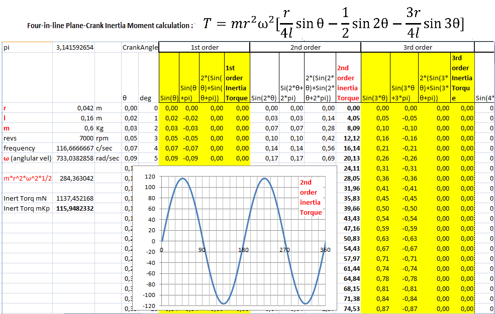
In the following array (Excel spreadsheet) it is applied the analytical formula for the unbalanced Inertia Torque of an in-line four-cylinder with plane crankshaft engine (the typical car engine, with crankpins at 0, 180, 180 and 0 degrees):
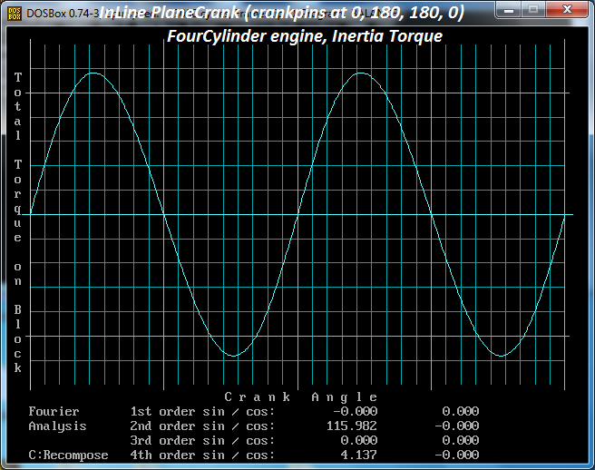
and here is the calculation of the same inertia torque with the balance program:
The specific formula stops in the 3rd order, missing the rest higher order components.
Worth to note: the 4th order Inertia Torque of the plane-crank 4-cyl is not zero: it is about 3.5% of the total inertia torque (see the second plot).
With the balance program (the crankshaft angle step is set at 1 degree) it is calculated the unbalanced 2nd order inertia torque as 115.982Kp*m (1137.8mN), while with the analytical method (the formula and the Excel array) the same inertia torque is calculated as 115.948Kp*m (1137.45).
The arithmetic calculations are quite simple:
For each crank angle the balance program calculates the position of the pistons, from two successive positions of a piston it is calculated the speed of the piston during the specific displacement (it is the displacement divided by the required time), with the speed of the piston for each crank angle the acceleration of the piston is calculated for every crank angle, with the acceleration of the piston the inertia forces are calculated, and so on).
The yellow areas of the array show the calculations of the first and third order components of the Inertia Torque of the plane-crank 4-cyl.
Both are zero.
This is so because:
Sin(θ) + Sin(θ+pi) = Sin(θ) - Sin(θ) = 0 (when the crankpins of the one pair of pistons (say the first and the fourth ones) are at θ angle, the crankpins of the other pair of pistons are at θ+pi angle).
In the balance program the angular velocity of the crankshaft is considered constant (say, like in the case the moment of inertia of the flywheel is extremely large).
With smaller and smaller moment of inertia of the flywheel, the angular velocity of the crankshaft gets more and more variable, which means the vehicle tends to increase / decrease its velocity two times per crank rotation (post with the two tri-cycles).
The PatVRA cures this problem of the plane-crank in-line four-piston engine: it allows the crankshaft to rotate at variable angular velocity and the drive wheels to rotate at constant angular velocity.