The only way you would see the torque amplitude given by that formula at the crankshaft output, would be an engine with zero rotating mass or infinite downstream inertia.
This!
Think of the following boundary condition configuration:
Torque acting on crank throws (inertia+gas load) and an imposed angular velocity somewhere downstream (say a dyno which can maintain the angular velocity regardless of driveline torsional vibration).
Because the angular velocity is constrained the equivalent inertia of the dyno rotor is infinite and all the throw torques are reacted through the driveline.
This scheme best represents driveline loading in the majority of practical applications. Even a car wheel accelerating without slip will see the infinite inertia of the ground.
In your last post you are correct on all counts.
What I suggest you do is use it to also calculate the torque caused by the gas loads which for the flat plane crank i4 engine will sum up to a 2nd order excitation.
You can find reference crank angle resolved cylinder pressure histories that you can then scale to typical peak gas loads (say 8 Mpa for a petrol NA engine, 12 MPa for a petrol turbo engine and about 18 MPa for a turbo diesel).
Now compare the magnitude of these 2nd order firing excitations to the magnitude of the 2nd order inertia torques you are trying to eliminate - you will find that in all typical road engines the firing excitations dominate.
Second point to consider is this:
Think of the driveline system as a typical vibration isolation problem. If the natural frequency of the driveline is much smaller than the excitation frequency then the transmissibility is very small. Transmissibility is defined as the ratio of output displacement (in your case at the wheel) to input displacement (flywheel).
For a perfectly rigid driveline the transmissibility is equal to 1 however for real world well designed drivelines it is much smaller than unity providing a very efficient filter for high frequency excitation. That is not only the 2nd order but the higher 3rd, 4th and so on. This on its own is a much better solution for controlling vibration at the tires!
The only way you would see the torque amplitude given by that formula at the crankshaft output, would be an engine with zero rotating mass or infinite downstream inertia.
This!
Think of the following boundary condition configuration:
Torque acting on crank throws (inertia+gas load) and an imposed angular velocity somewhere downstream (say a dyno which can maintain the angular velocity regardless of driveline torsional vibration).
Because the angular velocity is constrained the equivalent inertia of the dyno rotor is infinite and all the throw torques are reacted through the driveline.
This scheme best represents driveline loading in the majority of practical applications. Even a car wheel accelerating without slip will see the infinite inertia of the ground.
Infinite downstream inertia is almost worst case for TV's. Testing 4 cylinder engines on a dynamometer with high inertia requires a coupling with serious torsional compliance and damping. 4 cylinder cars get by with a heavy flywheel and lots of compliance between flywheel and the road - sprung clutch disc, drive shaft(s) and tyres. Torque converters are great too - as long as they don't lock them at low revs.
The PatVRA produces the torque pulse for each revolution, the motogp bike pulse on 2nd revolution being a 4 stroke cycle, to emulate this you need a primary gear reduction before the PatVRA mechanism.
Why not just place it in the wheel since the concept is about tire wear and slippage?
Infinite downstream inertia is almost worst case for TV's. Testing 4 cylinder engines on a dynamometer with high inertia requires a coupling with serious torsional compliance and damping. 4 cylinder cars get by with a heavy flywheel and lots of compliance between flywheel and the road - sprung clutch disc, drive shaft(s) and tyres. Torque converters are great too - as long as they don't lock them at low revs.
A typical transient dyno motor will easily have more than 10 times the inertia of the engines it can test and loads more torque.
Interestingly couplings only require damping if the driveline is designed to run in resonance at low engine speed. For race engines with high idle it is easy to lower the driveline frequency below the minimum engine speed in which case additional damping only serves to increase the transmissibility.
Transmissibility decreases with damping when the ratio of excitation frequency to natural frequency is 1 (resonance) but then crosses over and starts to increase with damping when the frequency ratio exceeds sqrt(2).
Since a racing engine in particular will operate almost exclusively at high frequency ratios adding damping is usually detrimental.
Zeta in the graph below represents ratio between viscous damping and critical damping so a value of 0.05 means that the viscous damping is 5% of critical damping.
For race engines with high idle it is easy to lower the driveline frequency below the minimum engine speed in which case additional damping only serves to increase the transmissibility.
I have seen dyno installations where driveline frequency was just above idle and TV's were so bad the engine could not be brought up to its operating range. Serious attempts to run up through the resonance actually broke the driveshaft (single cylinder, 300cc, 3" diameter driveshaft.)
Definitely not uncommon - in such situation the engine power is "efficiently" dissipated by various couplings, frictional interfaces and dampers to the extent that the net output is insufficient to increase the engine speed at any useful rate and pull through the resonance.
A similar phenomenon happens when drivers short shift into a driveline resonance and the car refuses to accelerate until they downshift again then upshift at higher engine speeds.
Ok, given this is ostensibly a 2T thread, what of the 'inertia torque' effects as experienced
in a high performance machine such as a racing motorcycle, as it relates to sudden power-cut
situations, where the throttle is snapped shut to 'save' an incipient 'highside' powerslide-crash?
Prior to the advent of sophisticated electronic traction control suite fitments & slipper clutches
to limit back torque* & off-throttle on-drive from that kind of 'inertia torque' on big 4T machines,
an 2T adept rider with quick reactions could better manage, due to that characteristic 2T lack of
engine braking, as may be seen at ~2:48 into the vid posted below:
Incidentally, that production motorcycle race was won by a 2T, against big heavy 4Ts.
*Ironically, high-performance 2T cars such as the Saab rally machines also used these
to prevent high rpm closed throttle overrun situations causing lubrication starvation
seizures (perhaps an ignition kill protocol would've been better, instead?)
"Well, we knocked the bastard off!"
Ed Hilary on being 1st to top Mt Everest,
(& 1st to do a surface traverse across Antarctica,
in good Kiwi style - riding a Massey Ferguson farm
tractor - with a few extemporised mod's to hack the task).
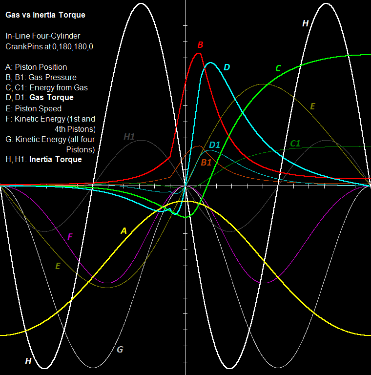
INERTIA and COMBUSTION torque of the typical 4-cyl engine
The horizontal axis is the crankshaft angle (zero degrees at the center of the axis, 360 degrees from left to right ends, 15 degrees per “division”(?) line):
The curve A (yellow) is the displacement of a piston of a 4-in-line flat-crank even-firing engine.
At the left-most and the right-most points of the A curve, the piston is at its BDC; at the middle the piston is at its TDC (you can think the points on the yellow line as successive positions of the piston crown, with the horizontal axis being the “roof” of the cylinder).
The “height” of the dead volume is the distance of the apex of the curve A from the center of the horizontal axis.
So, the distance of each point of the A curve from the horizontal axis is linearly proportional to the volume of the working medium in the cylinder (it includes the dead volume).
Starting with the curve A (yellow) and supposing 1 bar initial pressure and adiabatic (isentropic) compression / expansion, the curve B (red) is made.
It is the pressure inside the cylinder.
The adiabatic compression ends 15 degrees before the TDC; then energy is progressively provided to the working medium (the compression / expansion continues) until 15 degrees after the TDC; then it starts (and completes) the adiabatic expansion.
The increase of the energy of the working medium from -15 to 15 crank degrees is such that the iMEP (Indicated Mean Effective Pressure) is 14 Bar (giving, at 7,000rpm, an indicated power of 190kW (~260bhp) and (if the overall friction losses are taken as 15%) an output power of 220bhp on the crankshaft.
With the curve B (red) and the displacement of the piston (curve A), the curve C (green) is made; it is the energy provided to the crankshaft by the working medium (air, or air-fuel mixture).
During the compression this energy is negative (because the working medium absorbs energy from the crankshaft).
The curve C intersects the horizontal axis at about 25 degrees after the TDC.
The derivative (with respect to the crank angle) of the curve C (with reference to the crankshaft angle) is the curve D (thick cyan). The curve D is the combustion torque provided to the crankshaft. Before the TDC this torque opposes to the rotation of the crankshaft (compression stroke).
The curves B1 (brown) and D1 (thin cyan) are the cylinder pressure and the combustion torque at partial load operation (~1/3 of the full load, in this case).
If the engine had weightless (zero mass) pistons and connecting rods, the analysis would end here.
The curve E (dark green) is the piston speed and is calculated from the curve A (yellow). The A gives the displacement of the piston. Dividing the displacement of the piston by the required time it results the speed.
The curve F (purple) is the energy take-and-give between the pair of the pistons that move according the curve E and the crankshaft (for instance: from 75 degrees before the TDC till the TDC the kinetic energy of the two phased piston decreases, which means the crankshaft / flywheel are pushed to rotate faster) .
The curve G (gray) is the total energy take-and-give between all the four pistons of the 4-in-line plane-crank even-firing engine and the crankshaft.
The curve H (white and thick) is the derivative (with respect to the crank angle) of the curve G. It is the torque provided to the crankshaft by the set of the four pistons due to the variation of their speed during the cycle (for constant angular velocity of the crankshaft / flywheel).
At, say, 30 degrees before the TDC, all the four pistons decelerate losing kinetic energy which is provided to the crankshaft/flywheel pushing them to rotate faster.
The curve H1 (dark gray) is what the H for half revs.
The data used for the above calculations / analysis are:
4-in-line plane-crank (crank pins at 0, 180, 180 and 0 degrees) 4-stroke engine.
Stroke: 84mm
Bore: 95mm
Connecting Rod length: 160mm (center-to-center)
Displacement: 2.4lit
Each piston assembly mass: 0.6Kg (piston, piston rings, piston pin, and ~1/3 of the connecting rod mass).
7,000rpm (and 3,500rpm)
At top revs (say 7,000rmp, giving a 19.6m/sec mean piston speed) the inertia torque (curve H) is far larger than the full throttle combustion torque (curve D).
The useful torque (i.e. the combustion torque) the engine transmits to the drive wheels is like “noise” inside the much larger “inertia torque”.
Note: while the combustion torque is – mainly – positive, the inertia torque is equally negative and positive; what counts is the difference (from the bottom to the top) of each curve. On this reasoning, the combustion torque D is two times smaller than theinertia torque H.
There are systems that smooth out the torque going to the transmission line.
The question is how much energy is wasted during this “smoothing”.
Looking at the amplitudes and shapes of the H (white) and D (cyan) curves, the “efficiency” of the smoothing is quite questionable.
Even if an engine is to be used a couple of times – during its service life – at the top revs, the transmission has to be able to operate reliably at these revs.
At medium revs (3,500 rpm) the inertia torque (H1 curve) and the combustion torque (D curve) are comparable and the engine runs nicely at heavy / medium loads.
However, at medium revs and light loads (which is the typical case: think of cruising at 75mph (120Km/h) on a flat road), the combustion torque drops and gets as, say, the D1 curve: the dominant torque that passes (actually reciprocates) to the transmission line is the inertia torque again.
While the combustion torque is – more or less – constant along the useful rev range, the inertia torque falls with revs squared. Below, say, 2,000 / 2,500rpm the dominant factor is the combustion torque.
With the PatVRA the curves H and G are eliminated, allowing only pure combustion torque to pass to the transmission line, either at low revs, or at medium revs, or at the rev limit of the engine.
Besides the noise reduction, the vibrations reduction and the better feeling, it is also the power / energy saving.
The PatVRA makes the typical four behave (as regards the inerti torque and the transmittion of the power to the drive wheels) as the Wankel Rotary, the V8 engines.
The cylinder head of a Honda Civic 1600cc / 16v / VTEC was modified to pattakon-roler VVA to breath more efficiently:
The mean piston speed at 9,000rpm: 23m/sec.
Imagine the amount of inertia torque reciprocating to and fro the transmission line.
With the PatVRA it would run more quietly, more efficiently, more reliably and with better feeling of the drive tires hooking with the road.
For typical cars the difference will be smaller, yet there are still significant advantages.
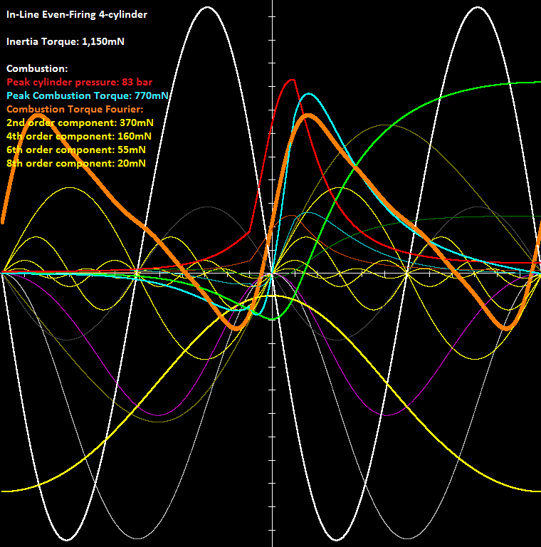
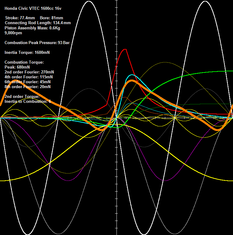
The following plot shows the Fourier analysis of the Combustion Torque at full throttle (i.e. of the cyan thick curve).
The yellow-thin curves are the 2nd, 4th, 6th and 8th order Fourier Components of the Combustion Torque.
The thick orange curve is the re-synthesis of the Combustion Torque from the above four Fourier components and is for the complete engine (while the cyan curve is for one only cylinder).
The peak cylinder pressure is 83bar (red curve).
The (second order) Inertia Torque is 3 times larger than the second order component of the Combustion Torque.
And this for full throttle.
At medium loads the relation gets "worse".
I.e. reciprocating mass per cylinder: 400+100+(600/3) = 600gr = 0.6Kg
The Peak Pressure is increased at 93 Bar, giving an iMEP of 16.5Bar.
At 9,000rpm the Inertia Torque is six times larger than the 2nd order Fourier Component of the Combustion Torque (at full open throttle).
Note: the 2nd order Fourier Component of the Combustion Torque is the dominant component of the Combustion Torque (see the yellow thin curves).
Imagine the difference with the PatVRA system (for the driver / passengers, for the clutch, for the transmission, for the wheels etc) .
..... slipper clutches
*Ironically, high-performance 2T cars such as the Saab rally machines also used these
to prevent high rpm closed throttle overrun situations causing lubrication starvation
seizures (perhaps an ignition kill protocol would've been better, instead?)
all 3 cylinder 2 stroke cars had on/off selectable freewheels (presumably the twins also)
the purpose was originally stated to be elimination of 4 stroking during over-run
(and Saab kept the freewheel even after pumped lubrication replaced petroil mix)
freewheels allowed clutchless gearshifts (so in some 4 stroke cars as early as c.1928 - very useful before synchromesh)
and reduced fuel consumption
eg Rover had the freewheel until 1960 - it being withdrawn as models with vacuum brake servos were introduced
though Saab 4 stroke cars ie the V4 96 and even the early 99 inline had freewheels several years later
btw we know the identity of the (French) Scott dealer who sold 2 Scott 3 cylinder engines to DKW in 1939
You are correct, I've repeated the same calculations and ended up with the same answer.
What I failed to notice originally is that the 2nd order inertia torque amplitude per crank is 4x the "per cylinder" value for flatplane l4 which means it will always dominate the combustion torque amplitude even though the "per cylinder" amplitude is generally lower.
You write: “The PatVRA produces the torque pulse for each revolution, the motogp bike pulse on 2nd revolution being a 4 stroke cycle, to emulate this you need a primary gear reduction before the PatVRA mechanism.”
No.
The PatVRA is neither producing torque, nor it “pulses” once per revolution.
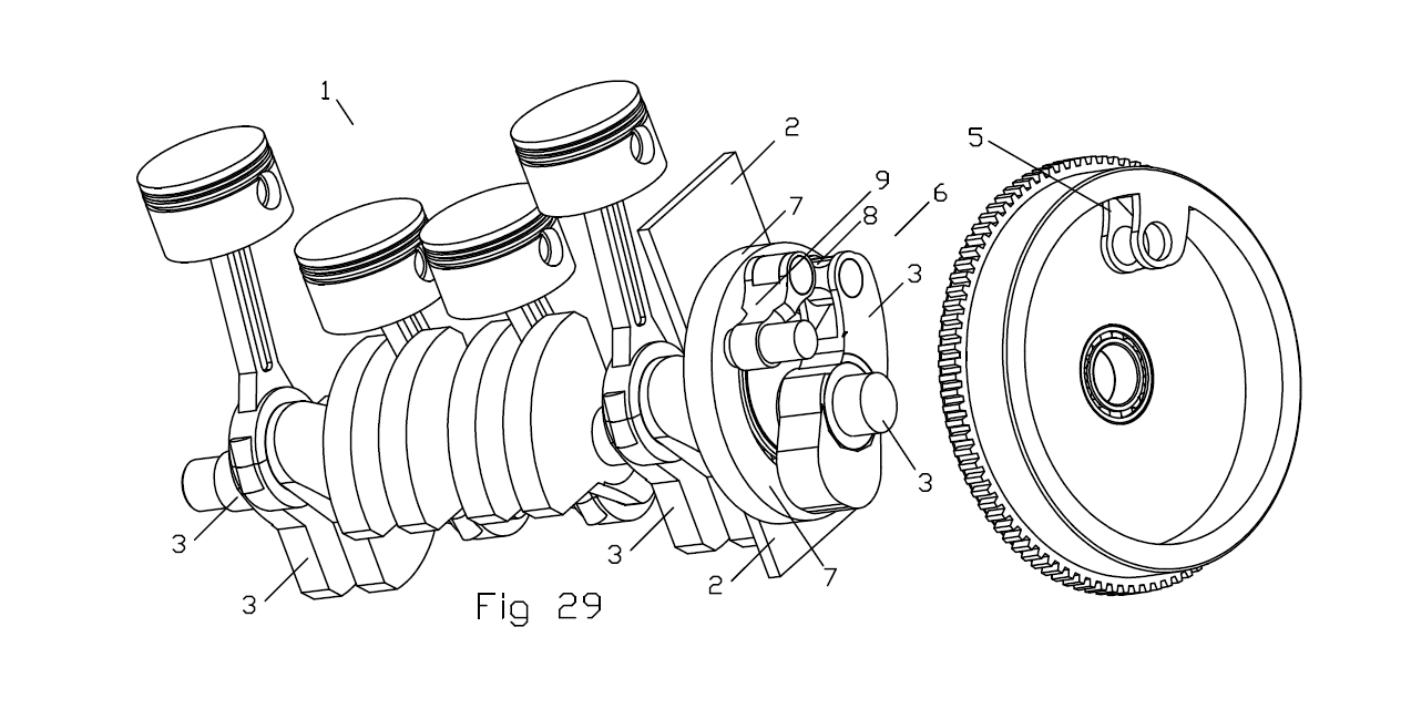
The same – more or less – mechanism is used in the PatVVD system (the continuously variable valve duration). In the PatVVD it is designed to produce one “pulse” (more correctly: one "deceleration / acceleration") per revolution:
Spot on the yellow pin connecting the green and blue small (connecting) rods: it is always at the same side (the side away the center of rotation) of the line connecting the other centers of the green and blue rods, providing one pulse per revolution.
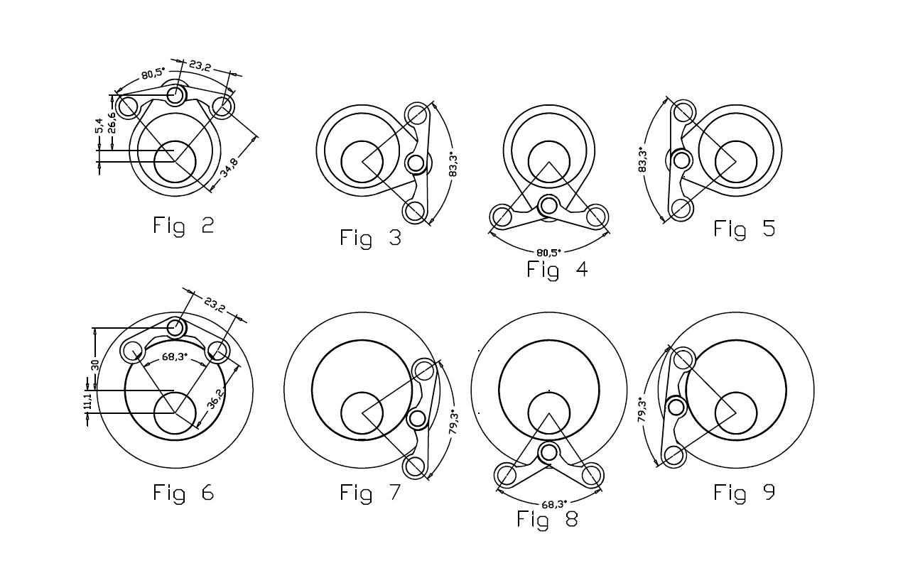
Here is the PatVRA mechanism for comparison:
At Fig 6, the angle between the two parts (say, the crankshaft and the flywheel) is small, after 90 degrees (i.e. after 1/4 of a revolution, Fig 7 ) the angle is wide, after another 90 degrees ( Fig 8 ) the angle is narrow again, and after another 90 degrees ( Fig 9 ) the angle is wide again. This gives two “pulses” per revolution.
Worth to mention here:
A twin in-line with crankpins at 0 and 0 degrees (say, as the Norton Commando) has both: first order inertia torque and second order inertia torque.
The PatVRA can be adjusted to “filter” both, the first and the second order inertia torques.
Think how.
Thanks
Manolis Pattakos
Last edited by manolis on 09 Dec 2020, 08:30, edited 1 time in total.