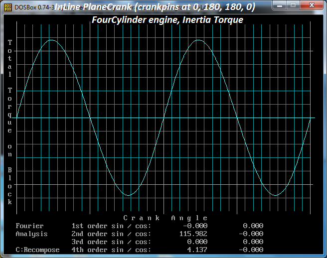
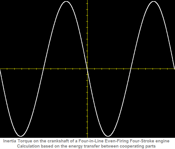
In the last posts there are three plots for the inertia and combustion torques; these plots were made based on the energy transfer between the cooperating parts of the engine.
The plots taken with the DOS balance program (older posts) were made based on the inertia forces, on the leaning of the connecting rods, on the resulting thrust forces onto the cylinder liners etc, etc.
Two substantially different approaches / solutions for the same problem.
Here is another plot for the Honda Civic engine revving at 9,000 rpm:
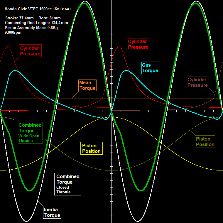
The yellow curve is the Position of a piston vs the crank angle..
The thin curves are the Cylinder Pressure inside the cylinders of the engine.
The cyan curve is the total Combustion Torque from all the four cylinders.
The orange horizontal line is the Mean Torque on the crankshaft of the engine (it is the mean value of the cyan curve). It is 170mN (the overall friction loss is taken as 20%) .
The white curve is the total Inertia Torque.
Adding the Combustion Torque (cyan curve) and the Inertia Torque (white curve) we take the Combined Torque on the crankshaft (green thick curve).
This is for the case the throttle is completely opened.
In case of closed throttle valve, the Combined Torque is the Inertia Torque (I.e. the white curve).
In simple words, when at 9,000rpm you release the gas pedal, the transmission line has to “deal” with a substantially larger torque: 3,200mN peak-to-peak versus 2,700mN peak-to-peak.
Hello J.A.W.
I.e. when the driver of a racing motorcycle powered by a 4-cyl flat-crank engine closes the throttle to decelerate before a curve, the rear tire “tries” to get what is “going on” (zero useful power, yet increased idling / useless power).
With the same engine modified to “crossplane” (like the Yamaha R1) the throttle opening is directly proportional to the torque being applied (provided) to the transmission and to the rear tire.
Thanks
Manolis Pattakos