Hello J.A.W.
You write:
"Have any hi-performance 2T designs considered/utilized this set-up from ram-jet
practice, . . .
A moveable device might accommodate flow rates for max-output over an rpm range? "
Here is a two-stroke design wherein by throttling / restricting the exhaust end (exhaust throat), the power output can be increased:
Quote from page 232:
For instance, think the PatOP wherein the scavenge pump capacity is 850cc while the cylinder capacity is only 635cc (scavenge ratio: 850cc/635cc = 1.34).
It doesn't matter it is a Diesel. It could operate as a carbureted 2-stroke petrol, too.
Here it is shown the big bore of the built-in scavenge pump of the PatOP, more at
https://www.pattakon.com/pattakonPatOP.htm ) :
Normally the exhaust ports close after the transfer ports.
So the surplus of air in the cylinder escapes through the exhaust (this is not bad if you think that the additional air, among others, cools down the exhaust piston crown and the exhaust ports on the cylinder).
But if you put a restriction / an obstacle at the end of the exhaust pipe, you can keep the pressure of the exhaust substantially higher than ambient (say, at 1.3 bar when the exhaust ports finally close). Yes, the scavenge pump will absorb more power from the crankshaft, however the trapped air in the cylinder will be much more than 635cc (nearly 850cc) and the power output will increase substantially.
End of Quote.
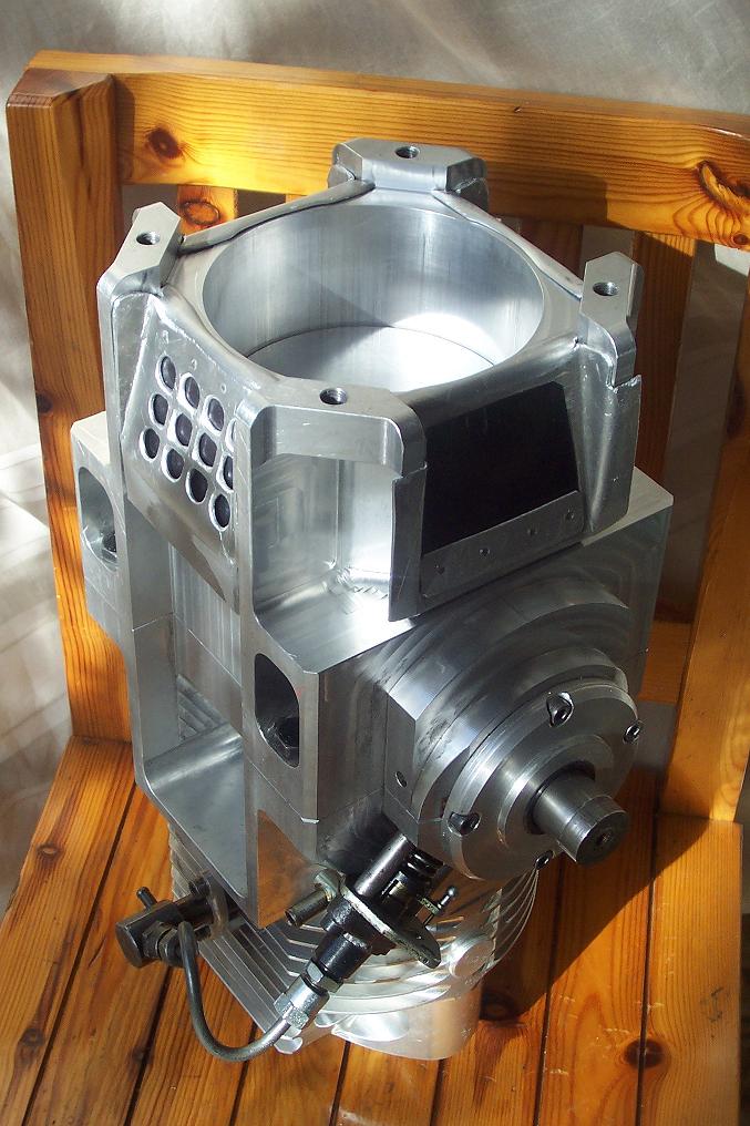
In the following photo it is shown the diameter of the combustion cylinder versus the diameter of the scavenge pump cylinder:
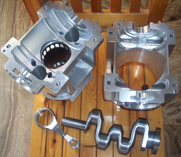
The overall stroke in the combustion cylinder is 64+64=128mm versus the only 64mm stroke of the scavenge piston, however the bore of the combustion cylinder is only 79.5mm while the bore of the scavenge cylinder is 130mm, resulting in a scavenge ratio of:
Scavenge Ratio = (64 * 130^2) / (128 * 79.5^2)=1.34
By putting a displaceable 'bullet' (ram-jet, as in your post) in the throat of the PatOP exhaust (or any other kind of throttle), substantially more fresh air can be trapped into the cylinder allowing more fuel to be injected and burnt (and so more output power to be provided).
Thanks
Manolis Pattakos