Link to the front page article
The article will be posted here in stages for discussion.

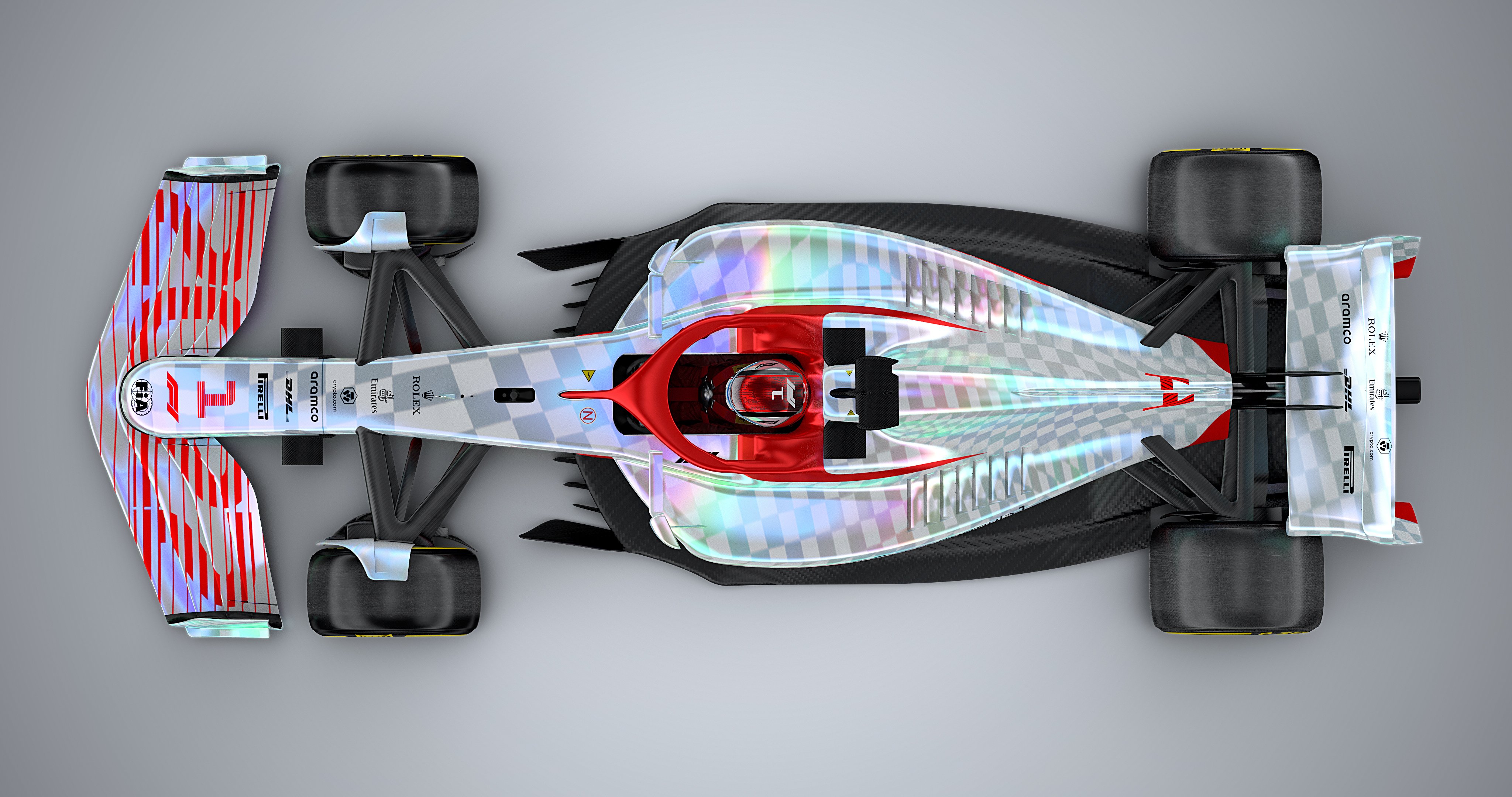
Ahead of the British Grand Prix Formula 1 revealed a full size model of its vision of next season's regulations. A couple of days earlier FIA released the latest edition of the rulebook. With the reality of the 2022 season looming, and assuming the rulebook will not change significantly between now and then, we investigate the contents of the regulation book to explain how cars will be designed.

Amazing work.jjn9128 wrote: ↑28 Jul 2021, 11:01This is a thread for discussion of the front page article detailing the 2022 F1 regulations. The article is another long read and goes through each bodywork group as described in the F1 regs.
The article will be posted here in stages for discussion.
https://db3pap006files.storage.live.com ... pmode=none


Thanks for the feedback. Is this any clearer?
Presumably the teams will want to have as much floor as they can manage close to the ground to maximise the ground effect, so the 50mm high section will be quite long, won't it?jjn9128 wrote: ↑28 Jul 2021, 16:04The minimum height along the tunnels is 50mm, the same as the floor step which has been in place since 1995, and teams could choose to have a flat section in the middle of the tunnel to squeeze the tunnel as close to the ground as possible. There is a minimum permitted radius of curvature of 25mm, with the exception of the small region outside the tunnel and just ahead of the rear tyre.
This is good. It means I can change some images to be clearer before the article actually goes upJust_a_fan wrote: ↑28 Jul 2021, 17:36Presumably the teams will want to have as much floor as they can manage close to the ground to maximise the ground effect, so the 50mm high section will be quite long, won't it?
Does the 25mm minimum radius apply where the tunnel wall meets the floor? I'd have though a nice 90deg angle here would be beneficial in creating a vortex from any air coming in from the side of the floor - in the same way that the approx 90deg angle where the current defined section of front wing meets the wing flaps and creates the Y250 vortex now.. This vortex would then "drop" in to the 50mm high tunnel section before helping air attachment through the diffuser. Is this sort of thing allowed by the rules?
g. Its complete surface must be tangent continuous, and any concave radius of curvature must be greater than 25mm. This is with the exception of regions of its surface that are within 60mm of the point [XR, Y, Z] = [-350, 495, 0] and visible from above.
h. Its complete surface must be tangent continuous, and any convex radius of curvature must be greater than 25mm. This is with the exception of regions of its surface that are:
i. Within 60mm of the point [XR, Y, Z] = [-350, 495, 0] and visible from underneath.
ii. In plan view, within 5mm of any point that, when viewed from above, lies on the boundary of the Floor. In the region -345 < XR < 440 this exception only applies below Z= 65.
"any convex radius of curvature must be greater than 25mm" would suggest that if you make the junction 90deg then no radius is required. A 90deg corner is not convex radius. A 90deg radius is r = 0.jjn9128 wrote: ↑28 Jul 2021, 18:13The 25mm radius is everywhere in the tunnel except a 120mm diameter sphere located at a point ahead of the rear tyre and from -345<<440 and below Z65 (basically the bottom of the diffuser endfence). I don't know if a sharp corner counts in that, because by definition it has no minimum radius of curvature... I think the FIA would say that it needs a radius.
g. Its complete surface must be tangent continuous, and any concave radius of curvature must be greater than 25mm. This is with the exception of regions of its surface that are within 60mm of the point [XR, Y, Z] = [-350, 495, 0] and visible from above.
h. Its complete surface must be tangent continuous, and . This is with the exception of regions of its surface that are:
i. Within 60mm of the point [XR, Y, Z] = [-350, 495, 0] and visible from underneath.
ii. In plan view, within 5mm of any point that, when viewed from above, lies on the boundary of the Floor. In the region -345 < XR < 440 this exception only applies below Z= 65.
0 << 25 thoughJust_a_fan wrote: ↑28 Jul 2021, 18:39"any convex radius of curvature must be greater than 25mm" would suggest that if you make the junction 90deg then no radius is required. A 90deg corner is not convex radius. A 90deg radius is r = 0.
I can see that interpretation being much discussed within the team and between team and FIA tech rep.

Oh, yes, there will be much discussion about what defines a radius. Classic FIA regulations really.jjn9128 wrote: ↑28 Jul 2021, 20:160 << 25 thoughJust_a_fan wrote: ↑28 Jul 2021, 18:39"any convex radius of curvature must be greater than 25mm" would suggest that if you make the junction 90deg then no radius is required. A 90deg corner is not convex radius. A 90deg radius is r = 0.
I can see that interpretation being much discussed within the team and between team and FIA tech rep.
Truth is I don't know how the FIA would rule here. I imagine they'd come down on the side of defining a minimum radius means there needs to be a radius.
Just to be clear is there a way you can draw on this where exactly you're talking about a sharp edge?
https://realsport101.com/wp-content/upl ... effect.jpg

I think you can if you avoid tangency between surfaces, in order to create an edge while increasing radius, and displacing the curved surface outboard, until it becomes the flat surface parallel to ground.Just_a_fan wrote: ↑28 Jul 2021, 23:40Oh, yes, there will be much discussion about what defines a radius. Classic FIA regulations really.jjn9128 wrote: ↑28 Jul 2021, 20:160 << 25 thoughJust_a_fan wrote: ↑28 Jul 2021, 18:39"any convex radius of curvature must be greater than 25mm" would suggest that if you make the junction 90deg then no radius is required. A 90deg corner is not convex radius. A 90deg radius is r = 0.
I can see that interpretation being much discussed within the team and between team and FIA tech rep.
Truth is I don't know how the FIA would rule here. I imagine they'd come down on the side of defining a minimum radius means there needs to be a radius.
Just to be clear is there a way you can draw on this where exactly you're talking about a sharp edge?
https://realsport101.com/wp-content/upl ... effect.jpg
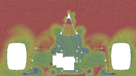
As for where the sharp edge might be - I figure anywhere where it might be useful in using an in / out flow to create a vortex. Little point doing it where the throat is narrowing as there are already some big VG / turning vanes there already. I could see it in the flat floor section as at some point there, the air is going to want to flow inwards thanks to the "suction" of the throat. I figure the junction of the small area of flat floor outboard of the tunnels and the upstand of the tunnels themselves. Make a 25mm radius junction between the vertical surface forming the wall of the tunnel and the roof of the tunnel and you effectively create a vortex-friendly region - sharp edge creating the vortex, nice rounded upper corner to keep the vorticity happy.
This idea is shown by this image from Willem Toet:
https://www.racetechmag.com/wp-content/ ... ic_001.jpg
The vortex rolls up around the sharp edge (nice blue vortex centres showing along the face of the tunnel).
I'm going to suggest that a team wanting to make use of this effect will have to set up the sharp edge along the whole of the edge they want to use. No way you can run a radius of 25mm and then go to a radius of 0 without a transition and a any such transition will fail the radius test.
A simple drawing of what I was trying to explain...BassVirolla wrote: ↑28 Jul 2021, 23:46I think you can if you avoid tangency between surfaces, in order to create an edge while increasing radius, and displacing the curved surface outboard, until it becomes the flat surface parallel to ground.


What's this? As in, what do the sentences past the comma refer to?jjn9128 wrote: ↑28 Jul 2021, 16:04
→ The longitudinal location of the front axle.
→ The longitudinal location of the front bulkhead, which cannot be more than 100mm ahead of .
→ The longitudinal location of the middle chassis bulkhead, this must be 875mm ahead of .
→ The longitudinal location of the rear of the cockpit entry template, which must be at least 1830mm behind .
→ The longitudinal location of the centre axis of the differential, must be within ±60mm of .
→ The car centre line and plane of symmetry for the car, the car must ostensibly be symmetrical except for some cooling variation and front wing flap adjustment.
→ The bottom of the car, also known as the reference plane.