Exhaust Blown Floor - Forward Exhaust Exit

Here are our CFD links and discussions about aerodynamics, suspension, driver safety and tyres. Please stick to F1 on this forum.
BreezyRacer
BreezyRacer
2
Joined: 04 Nov 2006, 00:31

Re: Exhaust Blown Floor - Forward Exhaust Exit

Post

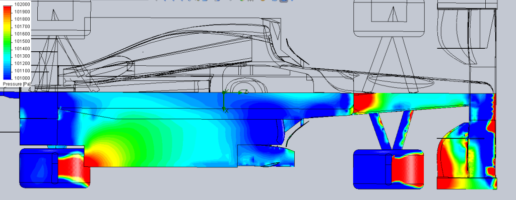
Yes, that's a very low pressure area as far forward in the chassis as anyone could hope for. The real test, since the low pressure area is out on the perimieter of the car, is to see how this performs in pitch. This design shows great potential for the Renault to wear tires really well as well as be superior in overall balance .. very important since static weight distribution is specified. I'm not sure that Newey and company can match this potential with the RB7 as it is.

How many teams are already working on this implementation? I say Red Bull and McLaren for sure .. maybe Merc, but they are always working on the next big idea and never committing to it .. Red Bull is fast .. they could maybe be ready by Bahrain.

xpensive
xpensive
214
Joined: 22 Nov 2008, 18:06
Location: Somewhere in Scandinavia

Re: Exhaust Blown Floor - Forward Exhaust Exit

Post

Would it be too much to ask for input data to the above images, such as xhaust density, specific heat capacity, massflow, speed and temperature, ambient temperature, pressure and relative speed; Finally the software and processor used?

Just before the forum begins second-guessing Enstone's, which are known for their focus on CFD btw, analysis? :lol:
"I spent most of my money on wine and women...I wasted the rest"

User avatar
horse
6
Joined: 23 Oct 2009, 17:53
Location: Bilbao, ES

Re: Exhaust Blown Floor - Forward Exhaust Exit

Post

ringo wrote:This is like myth busters, i'll go extreme and put the pipe under the floor facing straight back. See if the underfloor this is plausible or not. :mrgreen:
Thanks for humouring me. :roll:

Can you do a comparison of the pressure plots for the 3 simulations?
machin wrote:The leading edge of my model is pretty basic, and yet it produces a nice reduction in pressure:-
That's the suction "nose" peak that you'd see on the top of aerofoils at high angle of attack. Nice to see such good evidence for the upside down wing analogy.
"Words are for meaning: when you've got the meaning, you can forget the words." - Chuang Tzu

User avatar
Blackout
1563
Joined: 09 Feb 2010, 04:12

Re: Exhaust Blown Floor - Forward Exhaust Exit

Post


kilcoo316
kilcoo316
21
Joined: 09 Mar 2005, 16:45
Location: Kilcoo, Ireland

Re: Exhaust Blown Floor - Forward Exhaust Exit

Post

xpensive wrote:Just before the forum begins second-guessing Enstone's, which are known for their focus on CFD btw, analysis? :lol:
Erm. Would it not be the other way around?


i.e. is the CFD model presented here validated for the flow features observed/imposed?


For instance, did it use the Realizable k-E model to avoid the round-jet anomaly associated with the other k-E models?

User avatar
ringo
230
Joined: 29 Mar 2009, 10:57

Re: Exhaust Blown Floor - Forward Exhaust Exit

Post

xpensive wrote:Would it be too much to ask for input data to the above images, such as xhaust density, specific heat capacity, massflow, speed and temperature, ambient temperature, pressure and relative speed; Finally the software and processor used?

Just before the forum begins second-guessing Enstone's, which are known for their focus on CFD btw, analysis? :lol:
I have all those, but no one asked. :mrgreen: The density and specific heat wont be of much use if there is no real reason to analyze though.
The density change follows the drop in pressure and varies a lot, between 1.19 and 1.25 kg/m3 , supporting the reason why it's not accurate applying certain principles that assume constant density.

I changed the model a bit, mimicking the exhuast position a little better. I had it too low initially. This time it's higher but it points down so it blows under the airfoil at the turning vane.

What you should see though is how it behaves at low speeds like 150kph for tracks like monaco.
before that i'll show the density, and try to be a little more organized in presenting.
For Sure!!

segedunum
segedunum
0
Joined: 03 Apr 2007, 13:49

Re: Exhaust Blown Floor - Forward Exhaust Exit

Post

BreezyRacer wrote:This design shows great potential for the Renault to wear tires really well as well as be superior in overall balance .. very important since static weight distribution is specified. I'm not sure that Newey and company can match this potential with the RB7 as it is.
I don't think they'll be able to either. What Red Bull are doing is creating as much downforce as possible where the rear tyres and the grip is and asking the front to keep up. However, you've still got an uncontrolled mass in the middle of the car that is effectively cancelling that out to an extent and putting a sizeable lateral force on the tyres in corners. That's going to have a detrimental effect on grip and the longevity of the tyres as well.

I don't think anyone has thought that it would be possible to even explore creating downforce from an area that probably hasn't produced much since the days of ground effect, assuming of course that Renault can make this work. It could be one of those ideas that ends up having way too many variables attached to it. Still not convinced these exhaust gases are in an enclosed enough area to have much of an effect.

PNSD
PNSD
3
Joined: 03 Apr 2006, 18:10

Re: Exhaust Blown Floor - Forward Exhaust Exit

Post

kilcoo316 wrote:
xpensive wrote:Just before the forum begins second-guessing Enstone's, which are known for their focus on CFD btw, analysis? :lol:
Erm. Would it not be the other way around?


i.e. is the CFD model presented here validated for the flow features observed/imposed?


For instance, did it use the Realizable k-E model to avoid the round-jet anomaly associated with the other k-E models?
Wouldnt have said so for both questions. Id be supprised if solidworks used a 2 equation model... Though im very unfamiliar with the CFD built in to solidworks.

On the aero, I always thought the peak in downforce was always achieved at the entrance to the floor? I thought that was where Cp was it lowest rather than being exhaust induced? Or are you guys saying the exhaust will help this?

Again, no offense intended because the visualisations are nice, but does anyone have access a more advanced CFD code where perhaps a very basic underfloor geometry could be modelled with an exhaust vent/outflow in varying posistions? if most of the cars geometry could be discarded it would do away with alot of complexities?

User avatar
ringo
230
Joined: 29 Mar 2009, 10:57

Re: Exhaust Blown Floor - Forward Exhaust Exit

Post

I have access to ansys, but i haven't touched on it as yet. I suppose ansys is much more specialized.
Solidworks is sufficient depending on what you want. Computing power is the only limitation. These sims here are basically 5 minute calculations on a high end graphics PC.

I agree that a few pictures can't tell you everything, but you have to know what you want to investigate.
More can be done to pin point a specif interest, but again one has to know what one wants to investigate exactly.

Concerning the down-force under the floor there are 2 peaks. Splitter throat and diffuser throat; or any throat as a matter of fact. The FEE doesn't change the location of these or induce them.
Image
but i think at lower free stream speeds it can enhance them. I'm yet to try that.
For Sure!!

User avatar
PlatinumZealot
556
Joined: 12 Jun 2008, 03:45

Re: Exhaust Blown Floor - Forward Exhaust Exit

Post

Solid works floworks is quite good. Should be more than enough - unless you want to actually build the F1 car!

http://www.solidworks.com/sw/DemoLibrar ... ftware.htm
🖐️✌️☝️👀👌✍️🐎🏆🙏

☄️ Myth of the five suns. ☄️

☀️☀️☀️☀️☀️
LxVxFxHxN

xpensive
xpensive
214
Joined: 22 Nov 2008, 18:06
Location: Somewhere in Scandinavia

Re: Exhaust Blown Floor - Forward Exhaust Exit

Post

ringo wrote:
xpensive wrote: Would it be too much to ask for input data to the above images, such as xhaust density, specific heat capacity, massflow, speed and temperature, ambient temperature, pressure and relative speed; Finally the software and processor used?
...
I have all those, but no one asked. :mrgreen:
I just did above and I'm still curiously waiting.
"I spent most of my money on wine and women...I wasted the rest"

okibcn
okibcn
0
Joined: 04 Feb 2011, 15:09

Re: Exhaust Blown Floor - Forward Exhaust Exit

Post

ringo wrote:What you should see though is how it behaves at low speeds like 150kph for tracks like monaco.
Ringo, the CFD analysis of this model is a lot more than no simulation at all and you are giving us a nice graphs with valuable information so I encourage you to continuing doing so.

I just have a petition if possible: Could you make the same analysis at 250Km/h and 100Km/h? this way we would see the real effect of FEE at high and low speeds.

Thanks

Oki

segedunum
segedunum
0
Joined: 03 Apr 2007, 13:49

Re: Exhaust Blown Floor - Forward Exhaust Exit

Post

Yer, a rundown of the figures to go with the diagram will be nice because then we're still in "Will it? Won't it?" territory.

User avatar
machin
162
Joined: 25 Nov 2008, 14:45

Re: Exhaust Blown Floor - Forward Exhaust Exit

Post

xpensive wrote:Would it be too much to ask for input data to the above images, such as xhaust density, specific heat capacity.. etc, etc
I hope Ringo's reply doesn't result in endless discussions about whether the analysis should be re-run with the exhaust temp +/- 5k etc etc.

I'm sure he's used pretty decent figures......
COMPETITION CAR ENGINEERING -Home of VIRTUAL STOPWATCH

User avatar
spaman
0
Joined: 11 Feb 2009, 11:38

Re: Exhaust Blown Floor - Forward Exhaust Exit

Post

I think what they are trying to achieve is something like a.... well.... emmm... warp bubble. The gases spread out and create a barrier which the car is carrying with it while moving.

So it doesn't need to move through the surrounding atmosphere. It creates its own stable atmosphere.... let's call it warp bubble or EDA Exhaust driven atmosphere.

Freaky.