Key calculations in the Aerodynamics of the BT46

Post here information about your own engineering projects, including but not limited to building your own car or designing a virtual car through CAD.
alj
alj
1
Joined: 23 May 2012, 23:14

Key calculations in the Aerodynamics of the BT46

Post

Hi,

I'm new to F1Techncial. I have a small open wheeler, weighing ~500kgs with me in it. I have tuned the suspension (I realize I must increase the freq of the springs to allow for aero), and I want more from the setup, so I have read some Katz and McBerath, and become very interested in aero!

I'm interested in producing GE with side pods similar to the Lotus 79-80, incorporating the closed in wheels that Williams had. The angles I can guess from the pictures of the Lotus, and I will adjust these angles based on Track testing.

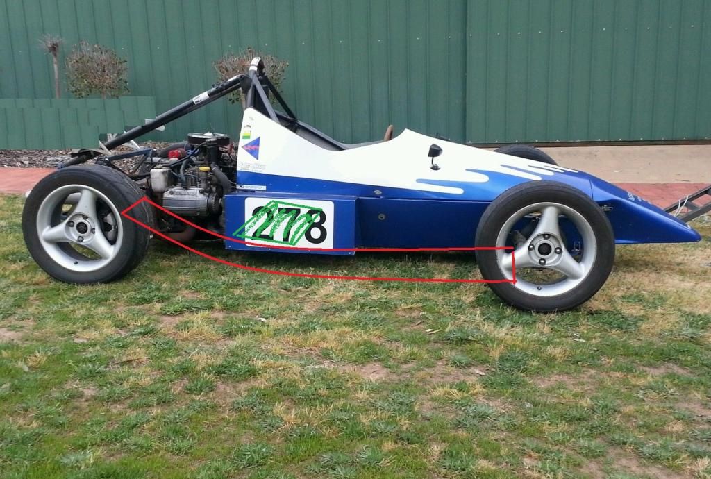
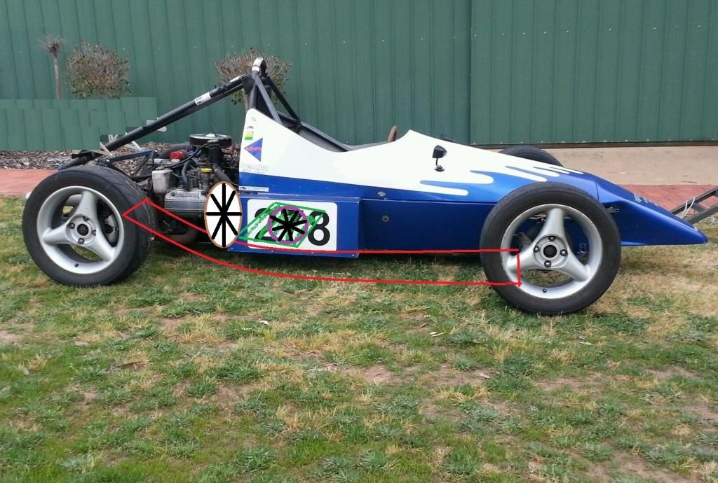
The part I need help with is I would also like to use the main/centre chassis underbody as a fan vacuum similar to the Brabham BT46. The main chassis size is just 2000x1000mm. I have a method of sealing the underside (similar to the 2J), My major question (and my weakness) is on calculations.

I have been looking at fans that can do this, but I do not know how to calculate the negative pressure that they can produce over the main chassis distance. Any help on the calculations would be appreciated!

From my research, I think a hovercraft fan would be easiest and most appropriate to use.

Thrust fans are designed to move the air at high speed with low pressure, where as a lift fan is designed to move the air at a slower speed with higher pressure. Using a thrust fan for lift only will likely cause the fan to stall due to the extreme blade angle. Combined Thrust / Lift fans are used for this purpose to satisfy both conditions in the beach craft.

So if I understand this right I want a lift fan. So I am considering using 2 x 22” fans ~@10hp each. The trick is to get the correct volume AND negative pressure, I just dont know how to calculate this.

Fan information:
22" Type 4 Fan with 5 fiberglass-reinforced polyamide blades. Blade pitch is adjustable. 3600 rpm produces 7,900cfm air flow at a static pressure of 4 inwg. requiring 9.2 hp @ 25 degrees blade pitch, or 10,200 cfm @ 30 degrees blade pitch requiring 12.3 hp; or 12,600 cfm @ 35 degrees blade pitch requiring 16.3 hp; or 14,300 cfm @ 40 degrees blade pitch requiring 20.6 hp; or 15,600 cfm @ 45 degrees blade pitch requiring 25 hp. Wt. 8 lbs.

OR

22" Type 3 Fan with 8 fiberglass-reinforced polyamide blades. Blade pitch is fixed. 3600 rpm produces 5,220 cfm air flow at a static pressure of 4 inwg. requiring 6 hp @ 25 degrees blade pitch, or 7,440 cfm @ 30 degrees blade pitch requiring 8.5 hp; or 10,300 cfm @ 35 degrees blade pitch requiring 14 hp; or 12,000 cfm @ 40 degrees blade pitch requiring 24 hp; or 14,800 cfm @ 45 degrees blade pitch requiring 20 hp. or 16,200 cfm @ 50 degrees blade pitch requiring 24 hp. Wt. 5 lbs.

Any help would be MUCH appreciated!

Facts Only
188
Joined: 03 Jul 2014, 10:25

Re: Key calculations in the Aerodynamics of the BT46

Post

This isn't helpful to you but I'd like to ask what series/country you are running the car in. The rules must be completely open to allow skirts and a fan.
For instance in the UK the MSA Bluebook (regulations for all race cars) prohibits such things for all and any competition cars.

Also would love to see some pictures of your car.
"A pretentious quote taken out of context to make me look deep" - Some old racing driver

alj
alj
1
Joined: 23 May 2012, 23:14

Re: Key calculations in the Aerodynamics of the BT46

Post

Facts Only wrote:This isn't helpful to you but I'd like to ask what series/country you are running the car in. The rules must be completely open to allow skirts and a fan.
For instance in the UK the MSA Bluebook (regulations for all race cars) prohibits such things for all and any competition cars.

Also would love to see some pictures of your car.
No series. I just enjoy aerodynamics and want to learn. I Have learnt quite a bit, but hoped someone on here can help me progress my knowledge and prqctical application. I don't have a huge budget (in fact it is tiny) but I can use the air to corner better than the others instead of thousands on my motor.

I've read quite a few posts here, this one relates most directly. But I need calculations.

http://www.f1technical.net/forum/viewto ... =6&t=13584

Xpensive wrote a little on negative pressure calculations of the underbody.

Greg Locock
233
Joined: 30 Jun 2012, 00:48

Re: Key calculations in the Aerodynamics of the BT46

Post

OK, what you need to do is, for a given fan curve, look at the relationship between pressure and flow rate (more pressure, less flow). then you need to work out the leakage of your skirts, which will also be a function of pressure (more pressure, more flow). Where those two curves meet is the operating point for that fan at that rpm. It is of course more complex than that as you will also have to overcome friction in the ducting etc. I have done the calcs on such a system, but it never got built, and I never got paid for it.

-Felix-
8
Joined: 16 Jan 2014, 14:24
Location: Green Hell

Re: Key calculations in the Aerodynamics of the BT46

Post

Interesting project and I can feel your interest in that field. I've never met another member of an FSAE team who didn't think of/dreamt of building a Lotus 79 Ground effect car :D But regarding your chassis size of 2000x1000, what's the wheel base? Because that's the main problem on FSAE cars, the car is way too short to incorporate a useful sidepod generating downforce. Talking about a sidepod only like Lotus 78, not a floorpanel with diffuser on the back..

alj
alj
1
Joined: 23 May 2012, 23:14

Re: Key calculations in the Aerodynamics of the BT46

Post

Greg Locock wrote:OK, what you need to do is, for a given fan curve, look at the relationship between pressure and flow rate (more pressure, less flow). then you need to work out the leakage of your skirts, which will also be a function of pressure (more pressure, more flow). Where those two curves meet is the operating point for that fan at that rpm. It is of course more complex than that as you will also have to overcome friction in the ducting etc. I have done the calcs on such a system, but it never got built, and I never got paid for it.
Thank you for your help, I'm sorry someone messed you about after you agreed to do work for them.

I can attempt the above calculations, I'm stuck on design. I see with the Redbull X1 they used a conical shape for the fan 'inlets', I'm not sure on a few points:
1) what is the best design for the fan inlets
2) Optimal ride height to give the car.
3) is it better to have more surface area for the active aero part?

Thank you again for your help!

Greg Locock
233
Joined: 30 Jun 2012, 00:48

Re: Key calculations in the Aerodynamics of the BT46

Post

Yes, it is better to have a big area, but your skirt design will limit exactly how much you can enclose. In practice we used a rectangular shape, as wide as possible. Skirts take up a surprising amount of vertical room.

I haven't got anything to add on the other stuff, the exhaust and intake obviously need to be smooth. I had big losses in the ductwork between the intake under the car and the fans, which were at the back of the car. I assume you are going for vertical axis fan(s)

AUS663
0
Joined: 11 Feb 2015, 01:12

Re: Key calculations in the Aerodynamics of the BT46

Post

Inlet is best served by 15 deg half angle cone, transitioning to a rectangular diffuser style inlet parallel to the floor, with the appropriate L.E. step. (assumes axial fans have horizontal axis of rotation) See CFD pages on this forum.

Given the proposed fan sizes i suspect the transitions will be symmetric. A conical diffuser will also help the mass flow across the fan leading to better static pressure recovery. Best recovery factor of 0.8 occurs at length to R1 ratio of 30:1 with a area ratio of 6.

Be careful of the variation of flow into the fan you do not want to ave the fan stall and loose pressure when cornering.

Best engineering book on fans is "Fan Engineering" by the Buffalo Forge Company. Howden Fans in melbourne may have a copy if you ring.

marcush.
159
Joined: 09 Mar 2004, 16:55

Re: Key calculations in the Aerodynamics of the BT46

Post

what you really need is the fan curve so you can really start making calculations .

The losses in ducts are really something on should not underestimate -so it´s not just how well you are sealing the area you are trying to evacuate but also how you direct the air towards the fan -each and every obstruction will call for parasitic losses
and you will need more power to achieve your goals!
the inlet design should be a gradual one reducing in area without sharp edges and avoiding areas of separation -easier said than done -trying to avoid 90degree bends at all cost -a straight shot into a big diameter fan is what you need .
This is also very true on the blades and their design as well -espicially the leading edges of fan blades are prone to substantial losses -reducing the effectiveness of the fan.

then -what is your ideal design for a fan ? A small high revving fan blade certainly has a different behaviour than a slower turning one with a big diameter...Think about the influence of pressure vs Volume with these variables...increasing revs will produce a steeper P/Q curve .Increasing fandiameter will flatten the P/Q curve but lift it overall ...very important when you cannot be sure if you are able to effectively seal your floor area effectively at all (important )times...guess what is the desired characteristic.

Fans are not just blades stuck to a hub .A major task is the design of guide vanes redirecting the flow in that area .

alj
alj
1
Joined: 23 May 2012, 23:14

Re: Key calculations in the Aerodynamics of the BT46

Post

As the fan type and placement is still in design phase I can change things up with only space as the restricting factor.

I am hesitant to post a picture of my open wheeler because it is not a million dollar machine, and you guys look at beautifully constructed F1 race cars and CFD pictures all day. But here it is, please don't flame too harshly:

Image

This is an older picture, I have the engine covered now and proper race rims/tyres. Once I have completed the GE side pods I will relocate the side radiators. My plan for the fan assisted aero was to place two 22" fans vertically either side on top of the GE side pods and duct into the area behind the drivers seat. Though the other option is to put one fan horizontally direct in that space.

I apologise for the terrible picture in advance. But it's just to present the idea:

Green is the area in the floor I can cut and duct (though the whole centre of the main body is available for fan assisted aero.
Red is the GE side pods, these will be separated by skirts similar to the 2J/Lotus 79-80.

Image

Brown fan shape indicates the vertical fan (duplicated on the other side pod). Purple fan shape indicates the choice for vertical fan placement.

The limiting factor here is the HP I can put through the fans. I plan to use hydraulics to run the fans and the maximum power I can put through them is an approximate 10hp. Hence my initial thoughts of utilising two fans, at 10hp each, on either side pod instead of one fan at 10hp.

I am fully open to suggestions. I am a complete novice and totally learning about fans et al.
Image

PS - I will get some CAD experience. These pictures and their quality actually embarrass me. Apologies.

Greg Locock
233
Joined: 30 Jun 2012, 00:48

Re: Key calculations in the Aerodynamics of the BT46

Post

Are those Ford of Australia Capri 15" wheels? (I think not, just checking)

Look on the bright side you've got a real circuit car unlike 99% of the blowhards on this forum, including moi.

alj
alj
1
Joined: 23 May 2012, 23:14

Re: Key calculations in the Aerodynamics of the BT46

Post

Greg Locock wrote:Are those Ford of Australia Capri 15" wheels? (I think not, just checking)

Look on the bright side you've got a real circuit car unlike 99% of the blowhards on this forum, including moi.
I'm not sure what type of rims those are, I really didn't like the look of them though, I think it made the car look even less professional and they were heavy! I have 13" race rims now with full slicks, much better!

Thanks for your kind words, I think this is an awesome forum, the collective minds here are amazing!

-Felix-
8
Joined: 16 Jan 2014, 14:24
Location: Green Hell

Re: Key calculations in the Aerodynamics of the BT46

Post

Did you apply photoshop on the rear aerofoil?

User avatar
RicME85
52
Joined: 09 Feb 2012, 13:11
Location: Derby
Contact:

Re: Key calculations in the Aerodynamics of the BT46

Post

Maybe its just made of t he same panels as the structure behind the car?


;)

alj
alj
1
Joined: 23 May 2012, 23:14

Re: Key calculations in the Aerodynamics of the BT46

Post

-Felix- wrote:Did you apply photoshop on the rear aerofoil?
The rear wing was removed as soon as I purchased the car. I didn't want it's incorrect placement to dominate the thread.