[KVRC] CCE LMP 2016

Post here information about your own engineering projects, including but not limited to building your own car or designing a virtual car through CAD.
User avatar
machin
162
Joined: 25 Nov 2008, 14:45

[KVRC] CCE LMP 2016

Post

Ok, so here are a couple of screenshots of my 2016 KVRC "Introductory Class" Bodykit; red Parts = Competition car Engineering, grey = Savage LMP01:-

Image

There's nothing particularly "innovative" about the design; the intention was simply to start with something that looks like it might be about right and then see how the results of the first test go and adjust from there (I have done no CFD on it myself).

There are really only four areas that I intend to adjust, and each of these are simple 2D extrusions:
  • Front wing/diffuser profile
  • Rear diffuser profile
  • Rear Wing profile
  • Cooling inlet by-pass restrictors
Each of these elements is drawn parametrically so that adjustment in fine increments is easy (i.e. no use of free-hand curves).

After the test race I intend to show detail sections of the car with CFD analysis and make the whole bodykit available to download for people who want to use it as a basic starting point.
COMPETITION CAR ENGINEERING -Home of VIRTUAL STOPWATCH

bill shoe
151
Joined: 19 Nov 2008, 08:18
Location: Dallas, Texas, USA

Re: [KVRC] CCE LMP 2016

Post

Looks interesting. Probably much optimization to be had in the combination of those 4 simple parameters.

The top-front view makes it look like the engine cover abruptly ends in a truncation instead of extending further aft like "normal". Am I just seeing it wrong?

User avatar
machin
162
Joined: 25 Nov 2008, 14:45

Re: [KVRC] CCE LMP 2016

Post

You're seeing it correctly... That's part of the "standard" bodywork in the introductory class and it is somewhat similar to the RedBull f1 car cooling outlet at the centre of the car... Where the outlet air from the heat exchangers "fills in" the void behind the safety cell...
COMPETITION CAR ENGINEERING -Home of VIRTUAL STOPWATCH

User avatar
RicME85
52
Joined: 09 Feb 2012, 13:11
Location: Derby
Contact:

Re: [KVRC] CCE LMP 2016

Post

I like your suspension cover solution, looks neat.
Is that an extra element/barge board I see between the sidepod and the trailing edge of the front wheel pod/cover?
Have you gone for the double deflection diffuser? Its difficult to tell what is going on in the second half, my tired sleep deprived eyes see it as almost flat from just behind the RWCL.
Good to have you on board this season Richard, will be interesting to see what you can come up with after all the things we learnt on last seasons car.

User avatar
CAEdevice
47
Joined: 09 Jan 2014, 15:33
Location: Erba, Italy
Contact:

Re: [KVRC] CCE LMP 2016

Post

Simplicity and optimization through a few parameters are a good choice.

I have doubts about the front wing (initial angle) and the rear wing seems to be a low df / high efficiency geometry. Why did not choose a 2 profiles wing? I'going to use a similar wing for the first race, but the only reason is that I had not enough time to change it :)

User avatar
machin
162
Joined: 25 Nov 2008, 14:45

Re: [KVRC] CCE LMP 2016

Post

The plan for the test race is simply to get a baseline set of figures for the car: so I'm running it in low downforce configuration to see how things work like that (ie I'm intentionally NOT going for a fast time). This will give me an idea of how efficient the car is for the later races. For the actual first race I will add downforce with a double element rear wing and some additional devices at the front.

The car does have the double inflection diffuser, but I suspect my initial part may be a little too extreme leaving the latter part a little too flat....

The additional "barge board" element is my "Cooling inlet bypass restrictor"... The idea is that this part can be adjusted to control flow into the cooling inlet...

More details coming after the test race!
COMPETITION CAR ENGINEERING -Home of VIRTUAL STOPWATCH


User avatar
LVDH
44
Joined: 31 Mar 2015, 14:23

Re: [KVRC] CCE LMP 2016

Post

Are you sure that exhaust exit is legal?


User avatar
variante
133
Joined: 09 Apr 2012, 11:36
Location: Monza

Re: [KVRC] CCE LMP 2016

Post

I'm happy that you've joined the championship.
Your bodywork layout looks like the obvious choice for the "Savage LMP01". No doubts it's going to perfom well since the first race (despite the conservative approach).

I have done a similar thing with the "inlet airflow controlling bargeboards".

User avatar
machin
162
Joined: 25 Nov 2008, 14:45

Re: [KVRC] CCE LMP 2016

Post

The cooling is definitely my biggest area of concern/uncertainty... Especially since cars with a similar sidepod layout last year performed not so well when we did the internal flow testing during the last round of 2015... I wanted to add a feature which I could incrementally adjust and the barge board/flow restrictor seemed OK.

I'm not planning on doing any of my own CFD testing, so all of the development will happen from the official race results... I suspect that this will mean I'm always a few steps behind; but that's OK... I'm doing it for the learning experience.
COMPETITION CAR ENGINEERING -Home of VIRTUAL STOPWATCH

User avatar
machin
162
Joined: 25 Nov 2008, 14:45

Re: [KVRC] CCE LMP 2016

Post

A little render to celebrate my test round submission....

Image
COMPETITION CAR ENGINEERING -Home of VIRTUAL STOPWATCH

User avatar
LVDH
44
Joined: 31 Mar 2015, 14:23

Re: [KVRC] CCE LMP 2016

Post

Looks like a nice and shiny melon.

User avatar
machin
162
Joined: 25 Nov 2008, 14:45

Re: [KVRC] CCE LMP 2016

Post

Very good.... #-o
COMPETITION CAR ENGINEERING -Home of VIRTUAL STOPWATCH

User avatar
machin
162
Joined: 25 Nov 2008, 14:45

Re: [KVRC] CCE LMP 2016

Post

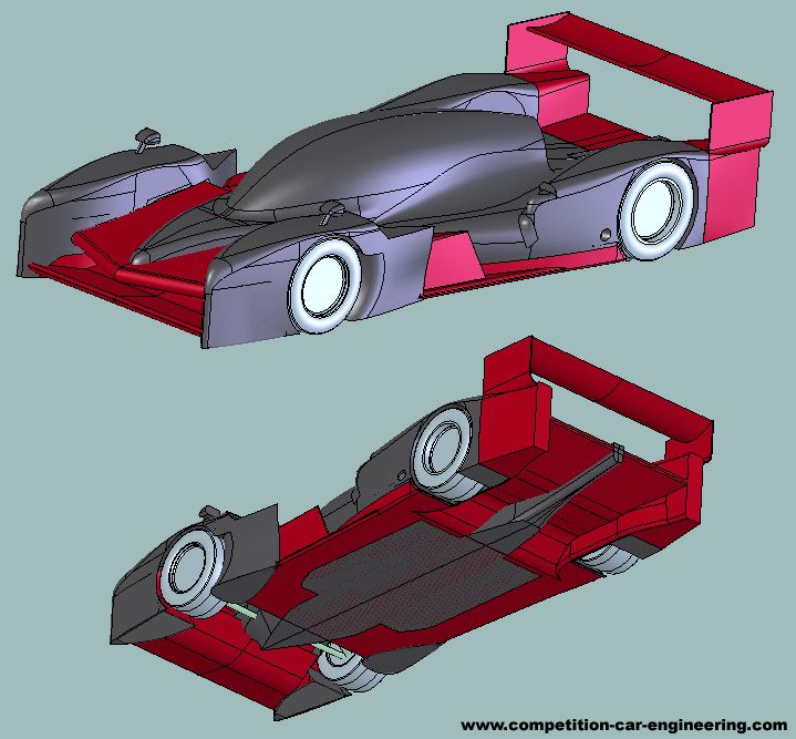
So the test results are in...
OCCFD wrote: The drag and downforce performance predicted by the simulation are:
Total drag: 1177.57 N
Drag coefficient - Cd: 0.59
Drag area - Cd.A: 0.98 m2
Total Downforce: -4309.58 N
Downforce coefficient - Cl: -2.16
Downforce area - Cl.A: -3.59 m2

CoP of downforce: 1.850 m along streamwise (Y) direction from Y = 0.00 m.
KVRC Only: Corrected CoP of downforce: 1.750 m along streamwise (Y) direction from Y = 0.00 m.

The pressure at intake and exhaust are:
Engine intake, Area: 0.016m2 - Compliant
Surface integral of pressure: 3.42 Pa.m2
Engine exhaust, Area: 0.010m2 - Compliant
Surface integral of pressure: 0.90 Pa.m2
Cooling intake, Area: 0.121m2 - Compliant
Cooling exhaust, Area: 0.081m2 - Compliant
Differential of surface integral of pressure: 17.44 Pa.m2
I'm reasonably pleased with the figures: no surprise that it has relatively low Cl.A as that is exactly the set-up that I was going for in the test race: now I have good basis and understanding for the air flows around the car.

The first plan of action has to be getting the cooling air flow sorted: at present there is insufficient pressure at the cooling inlet and the car therefore won't be able to make full power....

The tricky part now is trying to get more flow to the radiators, without (hopefully) reducing front-end downforce (in fact, I need more front downforce to balance the car).

The sketch below shows how air entering the front of the car (1) travels through and around the car:-
Image
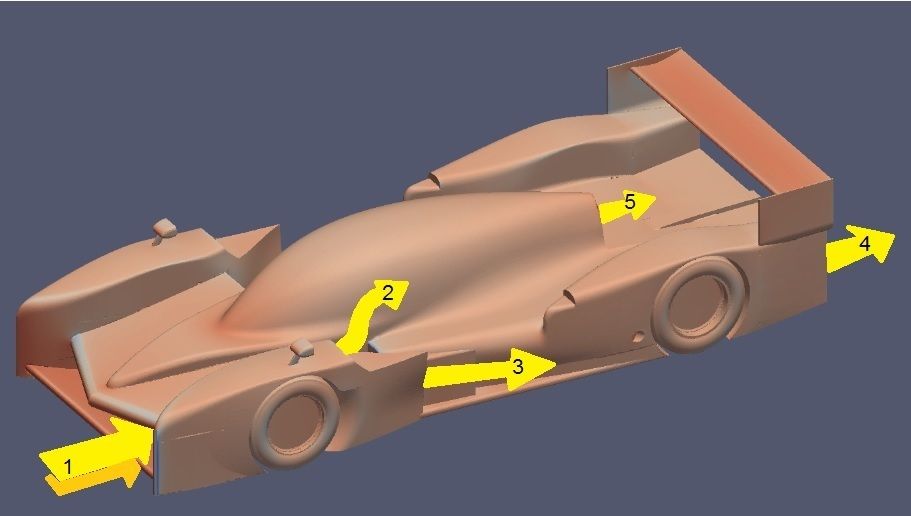
  • Some travels over the sidepod (2)
  • Some travels around the side of the sidepod(3)
  • some travels under the floor (4)
  • the remainder goes through the cooling system
In Class B we cannot simply increase the sidepod opening size as the inlet is a fixed ("Spec") part. My original plan had been to adjust the barge boards to direct less air around the sides of the car (3) and (hopefully) more through the cooling (5)... I suspect however that this would more than likely just reduce the amount of flow going through the car in the first place (1)... so I intend to change the design slightly at the front to encourage more air through the suspension (1) rather than over the top and to adjust the barge board (3)....

...The problem now is that because I'm not doing my own CFD I also need to sort out a high downforce package for the first official round....

....More images coming soon.....
COMPETITION CAR ENGINEERING -Home of VIRTUAL STOPWATCH