MCL33 possible nose cone solutions

Here are our CFD links and discussions about aerodynamics, suspension, driver safety and tyres. Please stick to F1 on this forum.
User avatar
turbof1
Moderator
Joined: 19 Jul 2012, 21:36
Location: MountDoom CFD Matrix

MCL33 possible nose cone solutions

Post

I'm creating this topic specifically so that speculation can be made on the MCL33 ducts and outlets of the current nosecone. Since we do not have any pictures of the back/underside of the nosecone, multiple solutions are perhaps possible.

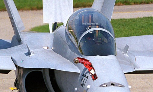
So guys, I'm actually breaking my mind on this one, trying to figure out possibilities how mclaren ducts their holes through the nose cone. The most standard option would be this:

Image

The sideholes basically containing NACA ducts, moving underneath the centre duct, and the middle hole having stacked vanes, all for legality sake.

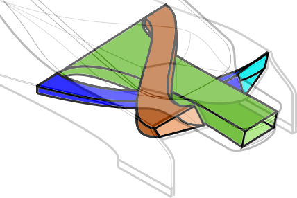
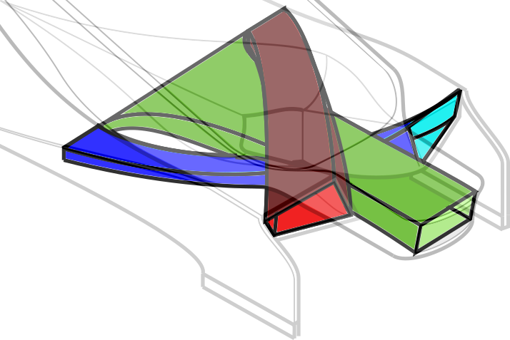
However, there might actually be another solution:
Image
I'm not 100% sure on the legality myself. I believe the ducts separate are legal, but the combination might (or might not) create legality issues on overlap.

Basically this set up allows to get rid of the vanes in the middle hole, allowing airflow to move more unblocked through the duct. More over, this would fit the actual pictures taken from the nose cone better, as there is only a single strut visible on them. Legality vanes could still be in place however, just deeper inside the nose cone.
#AeroFrodo

PhillipM
385
Joined: 16 May 2011, 15:18
Location: Over the road from Boothy...

Re: MCL33 possible nose cone solutions

Post

That also matches the heavily cambered shape on the underside of the outer ducts better.
The other thing I've been trying to see but we haven't had a clear photo of all weekend, is whether any of those ducts are blowing into the vertical fin that holds the cape - as it tapers in a 'v' from front to back, is it legal to have the back of that open?
(I'm thinking it would help accelerate flow around the side of it)

User avatar
jjn9128
769
Joined: 02 May 2017, 23:53

Re: MCL33 possible nose cone solutions

Post

It looks to me like each of the side ducts is split into 2, maybe for helping legality (X-section/whatever), maybe for splitting the direction of the air. Does it help that it looks like side ducts are above the tip hole in the Z direction? It looks that way at least, difficult to tell as all images have a slight angle on them... A shot from underneath would really help to identify what's going on :lol:
#aerogandalf
"There is one big friend. It is downforce. And once you have this it’s a big mate and it’s helping a lot." Robert Kubica

User avatar
turbof1
Moderator
Joined: 19 Jul 2012, 21:36
Location: MountDoom CFD Matrix

Re: MCL33 possible nose cone solutions

Post

PhillipM wrote:
16 May 2018, 16:53
The other thing I've been trying to see but we haven't had a clear photo of all weekend, is whether any of those ducts are blowing into the vertical fin that holds the cape - as it tapers in a 'v' from front to back, is it legal to have the back of that open?
(I'm thinking it would help accelerate flow around the side of it)
I think it can be legal if the open section is either NACA-ducted, or sits in the bulkhead area between 0mm and 150mm ahead of the front wheel centre line. Essentially any hole running like this:

is legal. And any holes sitting in that bulkhead area, are legal.
#AeroFrodo

User avatar
proteus
22
Joined: 13 Feb 2015, 14:35

Re: MCL33 possible nose cone solutions

Post

This is from Autosport, but it doesnt explain the middle very well:
If i would get the money to start my own F1 team, i would revive Arrows

trinidefender
317
Joined: 19 Apr 2013, 20:37

Re: MCL33 possible nose cone solutions

Post

proteus wrote:
16 May 2018, 20:14
This is from Autosport, but it doesnt explain the middle very well:
https://www.youtube.com/watch?v=3Ho0KVIYMbk
There are some glaring errors with that explanation.

Firstly while yes a vortex might form at the edges of the sides of the cape due to the lower pressure below and higher pressure above, it won't be a very strong vortex. Primarily due to the fact that there won't be that much of a pressure gradient. There isn't much of a curve below the cape to increase airflow velocity and drop the pressure.

Secondly, people keep comparing this to the Mercedes concept when in actuality they are quite different. The key difference being the direction that the vortex (if this cape even creates one of any substance) rotates.

On the Mercedes, the cape has the pieces at the very front which purposefully trip the airflow into a vortex. The higher pressure below rolls onto the top into a vortex as shown in the picture of the F-18.

Image
Image
Image

As you can see looking at that picture on the left side the vortex is clockwise, on the right, it is counterclockwise. On the McLaren setup if there is a vortex, looking at the nose from the front, on the left the vortex would roll counterclockwise on the left and clockwise on the right.

The reason why this detail is so important is the inside vortices coming off of the front wing. On the Mercedes they will be co-rotating and on the McLaren they will be counter-rotating. Co-rotating vortices gain strength, counter-rotating tend to cancel each other out. Considering how close together they are and the front wing vortex being much stronger, I wouldn't be surprised if it cancels out any vortex created by the horizontal section of the cape

I'm pretty sure the cape (and the rest of the nose) is more about setting up airflow for the rest of the car rather than providing its own downforce component.

roon
412
Joined: 17 Dec 2016, 19:04

Re: MCL33 possible nose cone solutions

Post

I think the long thin bars running the length of the front corners are for yaw. Turning air down the leeward, otherwise stalled, face.

Jef Patat
61
Joined: 06 May 2011, 14:40

Re: MCL33 possible nose cone solutions

Post

Image

User avatar
proteus
22
Joined: 13 Feb 2015, 14:35

Re: MCL33 possible nose cone solutions

Post

trinidefender wrote:
16 May 2018, 23:13
proteus wrote:
16 May 2018, 20:14
This is from Autosport, but it doesnt explain the middle very well:
https://www.youtube.com/watch?v=3Ho0KVIYMbk
There are some glaring errors with that explanation.

Firstly while yes a vortex might form at the edges of the sides of the cape due to the lower pressure below and higher pressure above, it won't be a very strong vortex. Primarily due to the fact that there won't be that much of a pressure gradient. There isn't much of a curve below the cape to increase airflow velocity and drop the pressure.

Secondly, people keep comparing this to the Mercedes concept when in actuality they are quite different. The key difference being the direction that the vortex (if this cape even creates one of any substance) rotates.

On the Mercedes, the cape has the pieces at the very front which purposefully trip the airflow into a vortex. The higher pressure below rolls onto the top into a vortex as shown in the picture of the F-18.

https://cdn.pbrd.co/images/HiqUTlg.jpg
http://www.lerx.net/Arbre/Lerx/Data/FA18D%20LERX.jpg
http://rumourcontrol.com.au/wp-content/ ... chell.jpeg

As you can see looking at that picture on the left side the vortex is clockwise, on the right, it is counterclockwise. On the McLaren setup if there is a vortex, looking at the nose from the front, on the left the vortex would roll counterclockwise on the left and clockwise on the right.

The reason why this detail is so important is the inside vortices coming off of the front wing. On the Mercedes they will be co-rotating and on the McLaren they will be counter-rotating. Co-rotating vortices gain strength, counter-rotating tend to cancel each other out. Considering how close together they are and the front wing vortex being much stronger, I wouldn't be surprised if it cancels out any vortex created by the horizontal section of the cape

I'm pretty sure the cape (and the rest of the nose) is more about setting up airflow for the rest of the car rather than providing its own downforce component.
Thank u for youre comment and explanation. I really enjoyed reading it, i am not the sharpest tool in the shed about aerodynamics, so i really appreiciate youre knowledge and understanding of it. So again, thank u very much :)
If i would get the money to start my own F1 team, i would revive Arrows

User avatar
turbof1
Moderator
Joined: 19 Jul 2012, 21:36
Location: MountDoom CFD Matrix

Re: MCL33 possible nose cone solutions

Post

So based on the confirmed outlets, kudos to Piola having those exits so accurate from to get go, I revised my idea of the ducting. So jjn9128, I don't think they actually split the side ducts, but I do believe they make an X-section:

Image
#AeroFrodo

User avatar
jjn9128
769
Joined: 02 May 2017, 23:53

Re: MCL33 possible nose cone solutions

Post

turbof1 wrote:
17 May 2018, 23:38
So based on the confirmed outlets, kudos to Piola having those exits so accurate from to get go, I revised my idea of the ducting. So jjn9128, I don't think they actually split the side ducts, but I do believe they make an X-section:

http://u.cubeupload.com/turbof1/XDucts.png
Really? It looks to me like the wide centre outlet is split three times. I can see a shadow about 1/3 along on the left which looks like where it is split ever so slightly set back... so the central duct and inner ducts of the outer ducts go to the middle, with the outer-outer ducts going to the edges... if that makes sense...

What you're suggesting would be quite a sharp turn... I would have thought the loses would make the ducting quite inefficient. I think you'd also see that difference in angle on the head on shot!
#aerogandalf
"There is one big friend. It is downforce. And once you have this it’s a big mate and it’s helping a lot." Robert Kubica

User avatar
turbof1
Moderator
Joined: 19 Jul 2012, 21:36
Location: MountDoom CFD Matrix

Re: MCL33 possible nose cone solutions

Post

jjn9128 wrote:
18 May 2018, 00:12
turbof1 wrote:
17 May 2018, 23:38
So based on the confirmed outlets, kudos to Piola having those exits so accurate from to get go, I revised my idea of the ducting. So jjn9128, I don't think they actually split the side ducts, but I do believe they make an X-section:

http://u.cubeupload.com/turbof1/XDucts.png
Really? It looks to me like the wide centre outlet is split three times. I can see a shadow about 1/3 along on the left which looks like where it is split ever so slightly set back... so the central duct and inner ducts of the outer ducts go to the middle, with the outer-outer ducts going to the edges... if that makes sense...

What you're suggesting would be quite a sharp turn... I would have thought the loses would make the ducting quite inefficient. I think you'd also see that difference in angle on the head on shot!
I could make the turn more fluent, yes. Let me give it a shot, one moment.
#AeroFrodo

User avatar
turbof1
Moderator
Joined: 19 Jul 2012, 21:36
Location: MountDoom CFD Matrix

Re: MCL33 possible nose cone solutions

Post

Image

I think this will work better in yaw.

You could of course still be right, as there are some structures in the outer inlets. However, splitting these outer ducts will create even more complexity, and since there are only 3 outlets in there, and splitting the outer inlets will create 5 ducts in total, means you somewhere along the way are going to merge ducts. Not counting in the splitting of the centre inlet.
I could be missing the point, but what's the gain from splitting into so many ducts? Solving the legality puzzle can be done a multitude of other, less complicated ways.

My impression is that these structures we see are small turning vanes, to straighten flow.

I will also try to get an impression of your idea tomorrow. There might be some benefit to be found in getting smaller tubes with softer turns.

I'm also working on those other illustrations for the record.
#AeroFrodo

User avatar
PlatinumZealot
551
Joined: 12 Jun 2008, 03:45

Re: MCL33 possible nose cone solutions

Post

turbof1 wrote:
17 May 2018, 23:38
So based on the confirmed outlets, kudos to Piola having those exits so accurate from to get go, I revised my idea of the ducting. So jjn9128, I don't think they actually split the side ducts, but I do believe they make an X-section:

http://u.cubeupload.com/turbof1/XDucts.png
It's all wrong. Try again.. 8)
🖐️✌️☝️👀👌✍️🐎🏆🙏

User avatar
turbof1
Moderator
Joined: 19 Jul 2012, 21:36
Location: MountDoom CFD Matrix

Re: MCL33 possible nose cone solutions

Post

PlatinumZealot wrote:
18 May 2018, 06:22
turbof1 wrote:
17 May 2018, 23:38
So based on the confirmed outlets, kudos to Piola having those exits so accurate from to get go, I revised my idea of the ducting. So jjn9128, I don't think they actually split the side ducts, but I do believe they make an X-section:

http://u.cubeupload.com/turbof1/XDucts.png
It's all wrong. Try again.. 8)
I did already. Spot the 10 differences 8).
#AeroFrodo